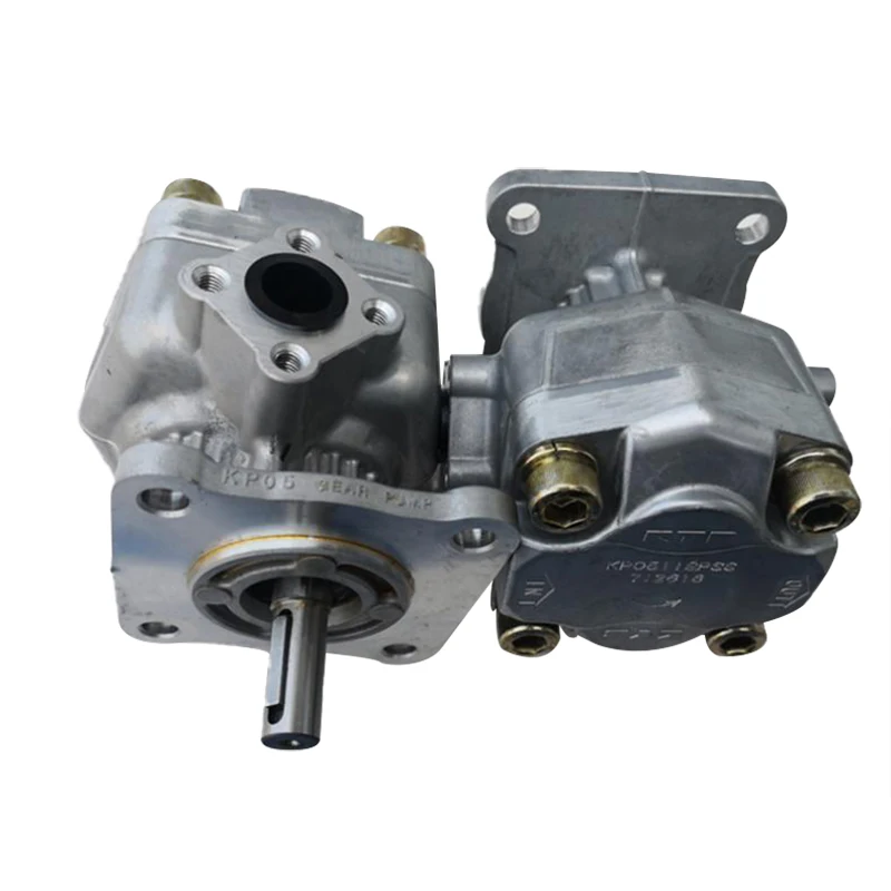
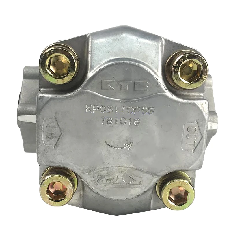
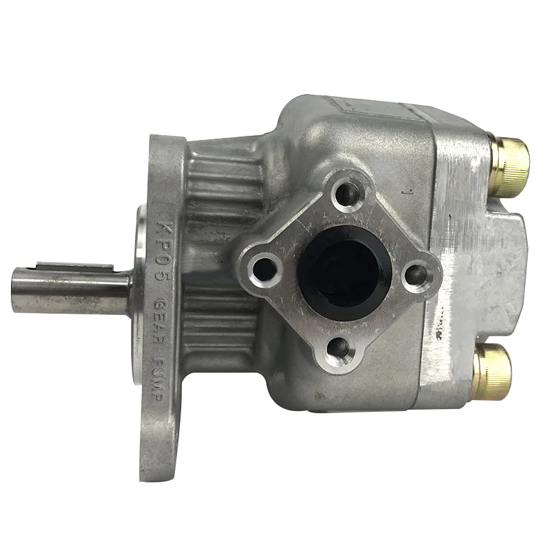
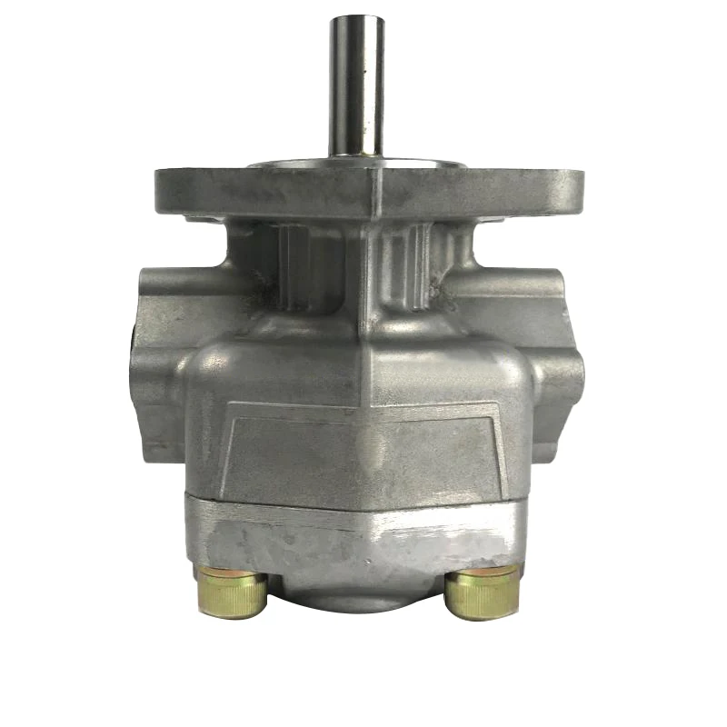
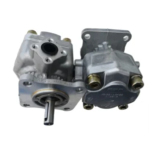
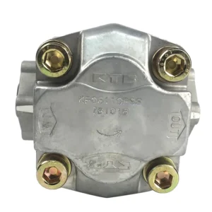
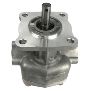
KP0540CPSS Oil Pump KP KFP KFS KP05 KP0530 KP0535 KP0540 KP0553 KP0560 KP0570 KP0588 Hydraulic Single Gear Pump
I. Core Technical Parameters
1. Basic performance parameters
Pump body type: External gear pump, open circuit design, single-stage single-acting, unidirectional rotation, suitable for medium and low pressure industrial hydraulic systems
Displacement parameters: Rated displacement 40 cc/rev (the “40” in the model “0540” is the core displacement identifier), geometric displacement 39.8 cc/rev, no variable adjustment function, output flow is directly proportional to the drive speed
Pressure parameters: Rated working pressure 210 bar, short-term maximum allowable pressure 250 bar (single duration ≤10 seconds), suction pressure range -0.02 to 0.05 MPa (gauge pressure), recommended working pressure 50 to 180 bar
Rotational speed parameters: Rated speed 2000 rpm (compatible with standard motors), maximum speed 2400 rpm (short-term ≤5 minutes), minimum stable speed 500 rpm. When the rotational speed fluctuation is ≤±2%, the flow stability error is ≤1.5%
Flow parameters: The maximum output flow at rated speed is 80 L/min (39.8 cc/rev×2000 rpm÷1000), the flow pulsation rate is ≤4%, the volumetric efficiency is ≥92% (under rated conditions), and the total efficiency is ≥83%
2. Structure and connection parameters
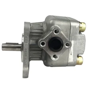
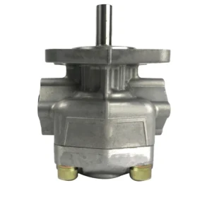
Structural type: High-strength cast iron pump body (tensile strength ≥300 MPa), integral design, with a pair of high-precision involute spur cylindrical gears installed inside. The gear material is carburized steel (surface hardness HRC58-62), and the pump body and end cover adopt a bimetallic composite structure to enhance heat dissipation. The front and rear end covers are each equipped with a set of copper-based alloy radial sliding bearings. The shaft seal adopts a double-lip fluororubber seal + skeleton support, with a static leakage of ≤0.5 mL/min
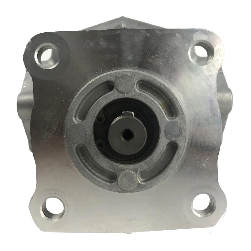
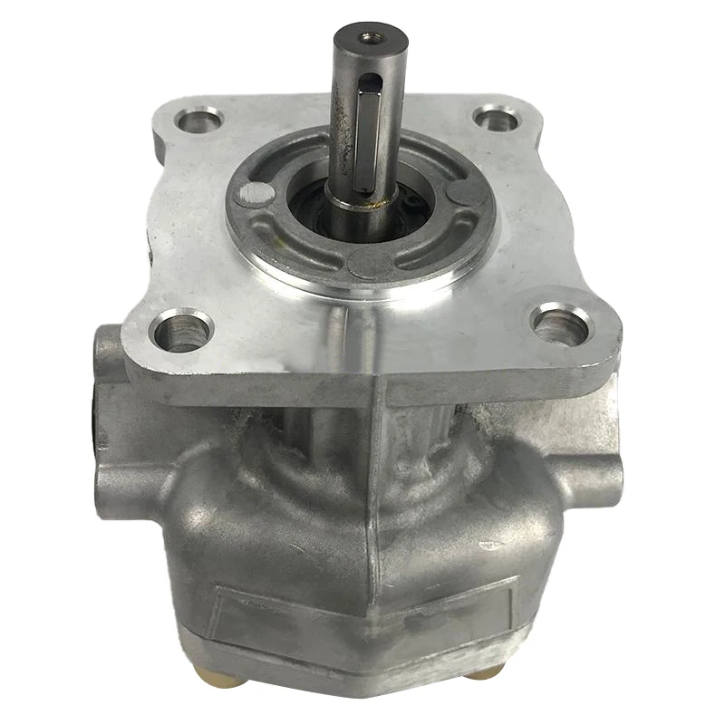
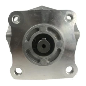
Installation specifications: Flange installation (conforming to ISO 3019-1 standard), 4-hole fixation, compatible with SAE type B flange; Oil port specifications: Suction port G1½ (internal thread), outlet port G1 (internal thread), drain port G1/8; The output shaft is connected by a flat key (14× 35mm), with an extension length of 80mm, and can be directly connected to the motor or reducer
Shape and weight: The overall dimensions (length × width × height) ≈350×220×190 mm, with a weight of approximately 22 kg. The structure is compact and suitable for equipment installation in Spaces with limited space
3. Medium and Environmental requirements
Applicable medium: L-HM 46 anti-wear hydraulic oil, compatible with L-HL general-purpose hydraulic oil, L-HV low-temperature hydraulic oil (for low-temperature conditions), and ISO VG 32-68 viscosity grade industrial lubricating oil
Medium characteristics: Allowable viscosity range 10 to 300 mm²/s, optimal working viscosity 15 to 50 mm²/s; Operating temperature: -20 ℃ to 80℃ (continuous operation), short-term up to 100℃ (cumulative ≤100 hours). Moisture content ≤0.05%. The contamination degree of solid particles should reach ISO 4406 16/13 grade. For precision systems, 15/12 grade is recommended
Environmental conditions: Protection grade IP65, suitable for industrial environments with humidity ≤95% (no condensation); The altitude is ≤ 2,500 meters. In high-altitude areas, the ventilation valve needs to be adjusted. The vibration tolerance acceleration is ≤12 g, and the noise level at 1 meter is ≤78 dBIi. Working Principle
This pump is an external gear pump, and its core working principle is based on the “volume change + meshing seal” mechanism:
The oil suction process: The motor drives the driving gear to rotate, which in turn drives the driven gear to rotate synchronously in the opposite direction. When the two gears separate from the meshing state, the volume of the oil suction chamber increases, creating a local vacuum. Under the action of atmospheric pressure, the oil in the oil tank enters the pump chamber through the oil suction pipe and the oil filter, filling the gap between the teeth
Oil transfer process: As the gears continue to rotate, the oil-filled teeth are carried to the other side of the pump body
Oil pressing process: When the gears remesh, the volume between the teeth decreases, and the oil is squeezed to generate high pressure, which is then discharged from the oil outlet to the system. The meshing point divides the pump chamber into an independent oil suction zone and an oil pressure zone, ensuring the unidirectional flow of oil
The output flow rate is directly proportional to the gear module, number of teeth, effective tooth width and rotational speed. The working pressure is determined by the system load. When the load increases, the leakage rate slightly rises, forming a self-balancing regulation. The pump is equipped with an unloading groove inside to alleviate the trapped oil phenomenon, reduce vibration and noise
1. Basic performance parameters
Pump body type: External gear pump, open circuit design, single-stage single-acting, unidirectional rotation, suitable for medium and low pressure industrial hydraulic systems
Displacement parameters: Rated displacement 40 cc/rev (the “40” in the model “0540” is the core displacement identifier), geometric displacement 39.8 cc/rev, no variable adjustment function, output flow is directly proportional to the drive speed
Pressure parameters: Rated working pressure 210 bar, short-term maximum allowable pressure 250 bar (single duration ≤10 seconds), suction pressure range -0.02 to 0.05 MPa (gauge pressure), recommended working pressure 50 to 180 bar
Rotational speed parameters: Rated speed 2000 rpm (compatible with standard motors), maximum speed 2400 rpm (short-term ≤5 minutes), minimum stable speed 500 rpm. When the rotational speed fluctuation is ≤±2%, the flow stability error is ≤1.5%
Flow parameters: The maximum output flow at rated speed is 80 L/min (39.8 cc/rev×2000 rpm÷1000), the flow pulsation rate is ≤4%, the volumetric efficiency is ≥92% (under rated conditions), and the total efficiency is ≥83%
2. Structure and connection parameters
Structural type: High-strength cast iron pump body (tensile strength ≥300 MPa), integral design, with a pair of high-precision involute spur cylindrical gears installed inside. The gear material is carburized steel (surface hardness HRC58-62), and the pump body and end cover adopt a bimetallic composite structure to enhance heat dissipation. The front and rear end covers are each equipped with a set of copper-based alloy radial sliding bearings. The shaft seal adopts a double-lip fluororubber seal + skeleton support, with a static leakage of ≤0.5 mL/min
Installation specifications: Flange installation (conforming to ISO 3019-1 standard), 4-hole fixation, compatible with SAE type B flange; Oil port specifications: Suction port G1½ (internal thread), outlet port G1 (internal thread), drain port G1/8; The output shaft is connected by a flat key (14× 35mm), with an extension length of 80mm, and can be directly connected to the motor or reducer
Shape and weight: The overall dimensions (length × width × height) ≈350×220×190 mm, with a weight of approximately 22 kg. The structure is compact and suitable for equipment installation in Spaces with limited space
3. Medium and Environmental requirements
Applicable medium: L-HM 46 anti-wear hydraulic oil, compatible with L-HL general-purpose hydraulic oil, L-HV low-temperature hydraulic oil (for low-temperature conditions), and ISO VG 32-68 viscosity grade industrial lubricating oil
Medium characteristics: Allowable viscosity range 10 to 300 mm²/s, optimal working viscosity 15 to 50 mm²/s; Operating temperature: -20 ℃ to 80℃ (continuous operation), short-term up to 100℃ (cumulative ≤100 hours). Moisture content ≤0.05%. The contamination degree of solid particles should reach ISO 4406 16/13 grade. For precision systems, 15/12 grade is recommended
Environmental conditions: Protection grade IP65, suitable for industrial environments with humidity ≤95% (no condensation); The altitude is ≤ 2,500 meters. In high-altitude areas, the ventilation valve needs to be adjusted. The vibration tolerance acceleration is ≤12 g, and the noise level at 1 meter is ≤78 dBIi. Working Principle
This pump is an external gear pump, and its core working principle is based on the “volume change + meshing seal” mechanism:
The oil suction process: The motor drives the driving gear to rotate, which in turn drives the driven gear to rotate synchronously in the opposite direction. When the two gears separate from the meshing state, the volume of the oil suction chamber increases, creating a local vacuum. Under the action of atmospheric pressure, the oil in the oil tank enters the pump chamber through the oil suction pipe and the oil filter, filling the gap between the teeth
Oil transfer process: As the gears continue to rotate, the oil-filled teeth are carried to the other side of the pump body
Oil pressing process: When the gears remesh, the volume between the teeth decreases, and the oil is squeezed to generate high pressure, which is then discharged from the oil outlet to the system. The meshing point divides the pump chamber into an independent oil suction zone and an oil pressure zone, ensuring the unidirectional flow of oil
The output flow rate is directly proportional to the gear module, number of teeth, effective tooth width and rotational speed. The working pressure is determined by the system load. When the load increases, the leakage rate slightly rises, forming a self-balancing regulation. The pump is equipped with an unloading groove inside to alleviate the trapped oil phenomenon, reduce vibration and noise
Iii. Product Features and Advantages
Simple and reliable structure: It is composed of only a few parts such as the pump body, gears, end covers, and bearings, without complex variable mechanisms. The failure rate is low, with an average mean time between failures of ≥ 10,000 hours. Maintenance is simple and the cost is low
Strong self-priming ability: It can achieve self-priming without an auxiliary pump, with an oil suction height of up to 500mm (under standard working conditions), suitable for various installation positions, and starts quickly (oil pressure is established within ≤3 seconds)
Good anti-pollution ability: It is less sensitive to oil contamination than plunger pumps and vane pumps, and can operate stably for a long time in harsh working environments, making it suitable for complex working conditions such as construction machinery
Wide speed adaptability range: It can operate stably within the range of 500 to 2400 rpm and is compatible with various power sources such as motors, internal combustion engines, and hydraulic motors
High efficiency and low consumption: The total efficiency under rated conditions is ≥83%, the volumetric efficiency is ≥92%, which saves 3 to 5 percentage points compared with similar products. The operating noise is ≤78 dB, improving the working environment
Wide temperature adaptability: With special bearing materials and sealing structures, it can operate within a wide temperature range of -20 ℃ to 80℃, making it suitable for use in different regions and seasons
High maintenance economy: The modular design reduces maintenance time by 50%, and the parts have strong universality. The normal working condition service life is ≥ 8,000 hours
Iv. Usage Functions and Purposes
1. Core functions
Constant flow oil supply: The output flow is directly proportional to the rotational speed, providing a stable flow for the hydraulic system and being suitable for working scenarios that require a constant flow
Pressure formation: Convert mechanical energy into hydraulic energy to provide the required pressure for the system and drive actuating elements such as hydraulic cylinders and hydraulic motors
System circulation: As a power source, it realizes the circulation of oil, and in combination with filters and cooling devices, it plays a role in heat dissipation and oil purification
Power transmission: The power of the prime mover is transmitted to the actuator through hydraulic oil to achieve the conversion and control of mechanical motion
2. Main uses
Industrial hydraulic systems: Provide power for equipment such as machine tool worktable feed, fixture clamping, and hydraulic lifting platforms
Auxiliary systems for construction machinery: applied in the pilot control of excavators, power steering assistance of loaders, lifting and tilting systems of forklifts, etc
Agricultural machinery: Compatible with devices such as hydraulic suspension for tractors, lifting of harvester headers, and control of farm tools
Logistics equipment: lifting and moving systems for driving hydraulic pallet trucks, stackers, conveyor belts, etc
Marine machinery: Provides hydraulic power for deck machinery such as ship mooring machines, winches, and hatch covers
Lubrication system: It can be used as a centralized lubrication pump for large equipment, providing lubricating oil for components such as bearings and guide rails
V. Applicable Machines and Scenarios
1. Adapt to the core machine
Injection molding machinery: Clamping systems, ejection devices and auxiliary oil circuits for medium and small-sized injection molding machines with a capacity of 100 to 200 tons
Pressure machinery: Auxiliary hydraulic systems for 200 to 500 ton hydraulic presses, punch presses, and bending machines (such as mold clamping and worktable adjustment)
Construction machinery: steering, lifting and tilting systems of excavators, loaders, forklifts, etc
Hydraulic drive devices for agricultural machinery: tractors, combine harvesters, rice transplanters, etc
Light industry machinery: roller pressure control for papermaking machinery, winding systems for textile machinery, impression devices for printing machinery
Vehicle equipment: Commercial vehicle hydraulic brake assist, dump truck lifting system, special vehicle-specific hydraulic devices
2. Typical application scenarios
Injection molding machine mold closing: In a 150-ton injection molding machine, a stable pressure of 180 bar is provided for mold closing, a flow rate of 50 L/min is used for rapid mold closing, and a flow rate of 10 L/min is used for low-pressure holding. The pressure fluctuation is ≤±1.5 bar, ensuring stable product quality and reducing energy consumption by approximately 15%
Construction machinery steering: Hydraulic steering systems suitable for loaders and excavators, providing a flow rate of 60 to 80 L/min and a pressure of 160 bar. The steering is light and flexible, remaining stable under heavy loads and harsh working conditions, enhancing operational safety
Logistics equipment lifting: Used for hydraulic lifting platforms and forklifts, it provides a flow rate of 70 L/min and a pressure of 140 bar, enabling rapid and smooth lifting of goods. The positioning error is ≤5 mm, and the working cycle time is reduced by 20%
Agricultural machinery operation: Compatible with the hydraulic suspension system of tractors, it provides a stable pressure of 60 bar and a flow rate of 40 L/min, controls the lifting and tilling depth of farm tools, ADAPTS to different soil conditions, and improves operation efficiency
Six. Similar models
1. Different models of the same series displacement
KP0530CPSS: Rated displacement 30 cc/rev, rated pressure 210 bar, suitable for small hydraulic systems and lubrication systems. It is 15% smaller in volume than the original model, weighs approximately 18 kg, and has a flow rate of 60 L/min at the rated speed
KP0550CPSS: Rated displacement 50 cc/rev, rated pressure 210 bar, suitable for medium-sized hydraulic systems and construction machinery. It features high power density and a flow rate of 100 L/min at rated speed, making it suitable for heavier loads
KP0563CPSS: Rated displacement 63 cc/rev, rated pressure 210 bar, suitable for large-scale hydraulic systems and special machinery, with stronger power. Flow rate at rated speed 126 L/min, suitable for heavy-duty working conditions
2. Models with the same displacement but different functions
KP0540CGSS: Type with built-in relief valve, with a set pressure of 210 bar. It automatically unloads when the system is overpressurized, providing additional protection. It is suitable for systems with large load fluctuations. The cost is approximately 12% higher than that of the original model
KP0540AGSS: Type with pressure compensator, it can automatically adjust the flow rate according to system requirements, maintain stable output pressure, and improve energy-saving effect by 10 to 15%. It is suitable for precision systems
KP0540AHSS: High-speed type, with optimized bearing and seal design, the maximum rotational speed can reach 2800 rpm, and the flow rate is increased by 15%, making it suitable for high-flow demand scenarios
KPO530AGV,KPO530AHSS,KPO540AGSS,KPO540CGSS,KPO540AHSS,KPO540CHSS,KPO540CQSSKPO553AGSS,KP0553CGSS,KP0553AHSS,KPO553CHSS,KP0553CJSS, KP0553-53CSES,KPO553ASSS,KPO553CTS,KPO560AGSS,KPO560CGSS,KPO560AHSS,KPO560ARSS,KPO560ASSS,KPO560CSSS,KPO57OAGSS, KKPO570AHFS,KPO570AHSS,KPO570CHSS,KPO570AJSS,KPO570CJSS,KPO570ANSS, KPO57OASSS, KKPO570ATSS,KPO588AGSS,KPO588CGSS,KPO588AHSS,KPO588CHSS,KPO588AJSS,KPO588CJSS, KKPO588ARSS, KPO588ASSS,KPO588CSSS,KPO588ATSS,KPO588AVS,KPO510CHSS, KPO510ASSS, KPKPO511ASSS,KPO511C,KPO512C,KPO12ASSS,KPO512CSSS,KPO512CPSS,KPO513CVS,KPO513-60AK,KPO514ASSS,KPO523CPSS,KPO530CPSS,KPO535CPSS,KPO540CPSS,KPO553CPSS,KPO560CPSS,KKP0588CPSS,KPO5106CPSS,KP05123CPSS
Vii. Precautions for Use
1. Installation points
The installation plane must be flat to ensure that the coaxiality error between the pump body and the drive shaft is no more than 0.05mm. Elastic couplings should be used for connection. Rigid connection is strictly prohibited to avoid additional radial force (≤ 80N) acting on the pump shaft
The suction pipe should be a short straight pipe with an inner diameter of ≥ 32mm and a length of no more than 1.2m. The number of elbows should be reduced. A coarse filter of 80 to 100 mesh should be installed at the suction port, and the distance from the bottom of the oil tank should be ≥ 150mm. The inner diameter of the oil pressure pipe is ≥ 20mm, and it needs to be fixed and supported. An exhaust valve is installed at the highest point. The oil drain pipe is separately connected to the oil tank for direct oil return and does not share with other pipelines to prevent back pressure
Rotate strictly in the direction indicated by the arrow on the pump body. Reverse rotation will cause the suction and discharge directions to be reversed, poor lubrication and seal damage
2. Operation and Maintenance
Before the first start, fill the pump with clean hydraulic oil and manually turn it 2 to 3 times to ensure there is no jamming. Jog to start and check the rotation direction. Run without load for 5 to 10 minutes (when the oil temperature rises above 30℃), then gradually load. It is strictly forbidden to suddenly load to the rated pressure
Key parameters to be monitored during operation: Normal operating temperature is 40 to 60℃, with a maximum not exceeding 80℃. If the temperature rises sharply by more than 15℃, the machine should be shut down for inspection. The pressure does not exceed 210 bar, and the fluctuation range is ≤±5 bar. The noise should be uniform. If abnormal whistling or knocking sounds occur, stop the machine immediately for inspection. The static leakage at the shaft seal should be no more than 0.5 mL/min and the dynamic leakage no more than 1.5 mL/min. If the leakage exceeds the standards, the seal should be replaced in time
Daily maintenance cycle: Check the oil level, oil temperature, oil pressure and leakage every 50 hours. Check and clean/replace the filter every 200 hours; Change the hydraulic oil and clean the oil tank every 1,000 hours. Check the wear of bearings and gears every 2,000 hours and replace them if necessary
3. Special Precautions
It is strictly prohibited to start or operate without oil. Brief dry running (>3 seconds) will cause severe wear on gears and bearings that cannot be repaired
Ensure that the suction oil pipeline is well sealed to prevent air from entering. The suction pressure should not be lower than -0.02 MPa to avoid cavitation damage to the pump body
When starting at low temperatures (ambient temperature <5℃), the oil needs to be preheated to above 10℃. When the ambient temperature is above 35℃ or it works continuously for a long time, a cooling device should be installed to ensure that the oil temperature is ≤80℃
Before shutting down, unload (reduce to low pressure) and run for 3 to 5 minutes. Once the oil temperature is ≤60℃, cut off the power to prevent the high-temperature oil from solidifying
4. Storage and Maintenance
Short-term storage (≤30 days) : Clean the surface of the pump body, seal all oil ports to prevent foreign objects from entering, and store in a dry and well-ventilated place, avoiding direct sunlight and moisture
Long-term storage (>30 days) : Thoroughly clean the inside and outside of the pump, inject anti-rust oil, apply anti-rust grease to the output shaft and wrap it with a protective cover. Check once every three months and supplement anti-rust measures. Before reactivation, replace all seals, clean the interior, and conduct a no-load test run to confirm normal operation before putting it into use