


PVG PVG048 PVG065 PVG075 PVG100 PVG130 PVG150 Variable Displacement Axial Hydraulic Piston Pump PVG-150-A1UV-RGFS-P-1NNSN
I. Core Technical Parameters
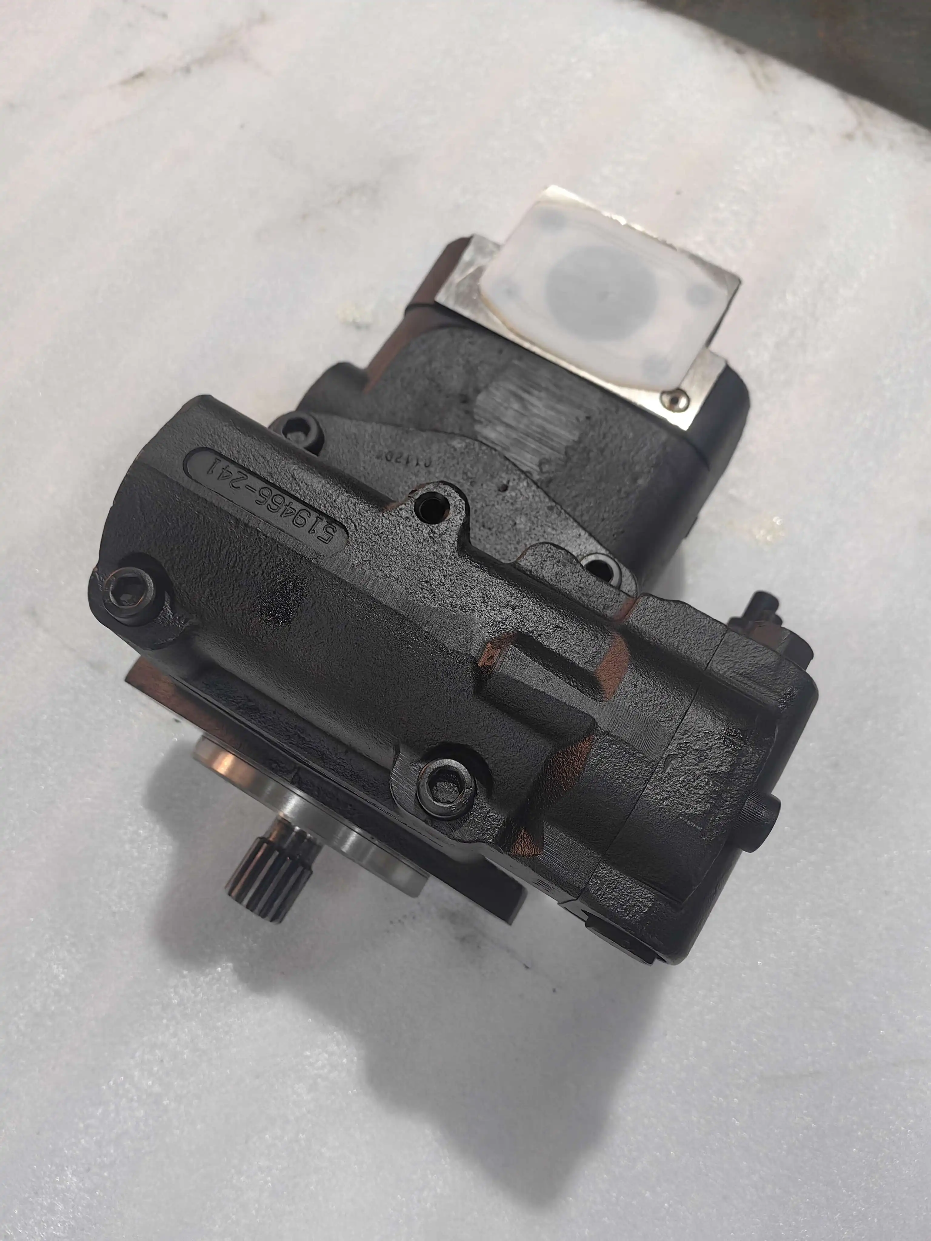
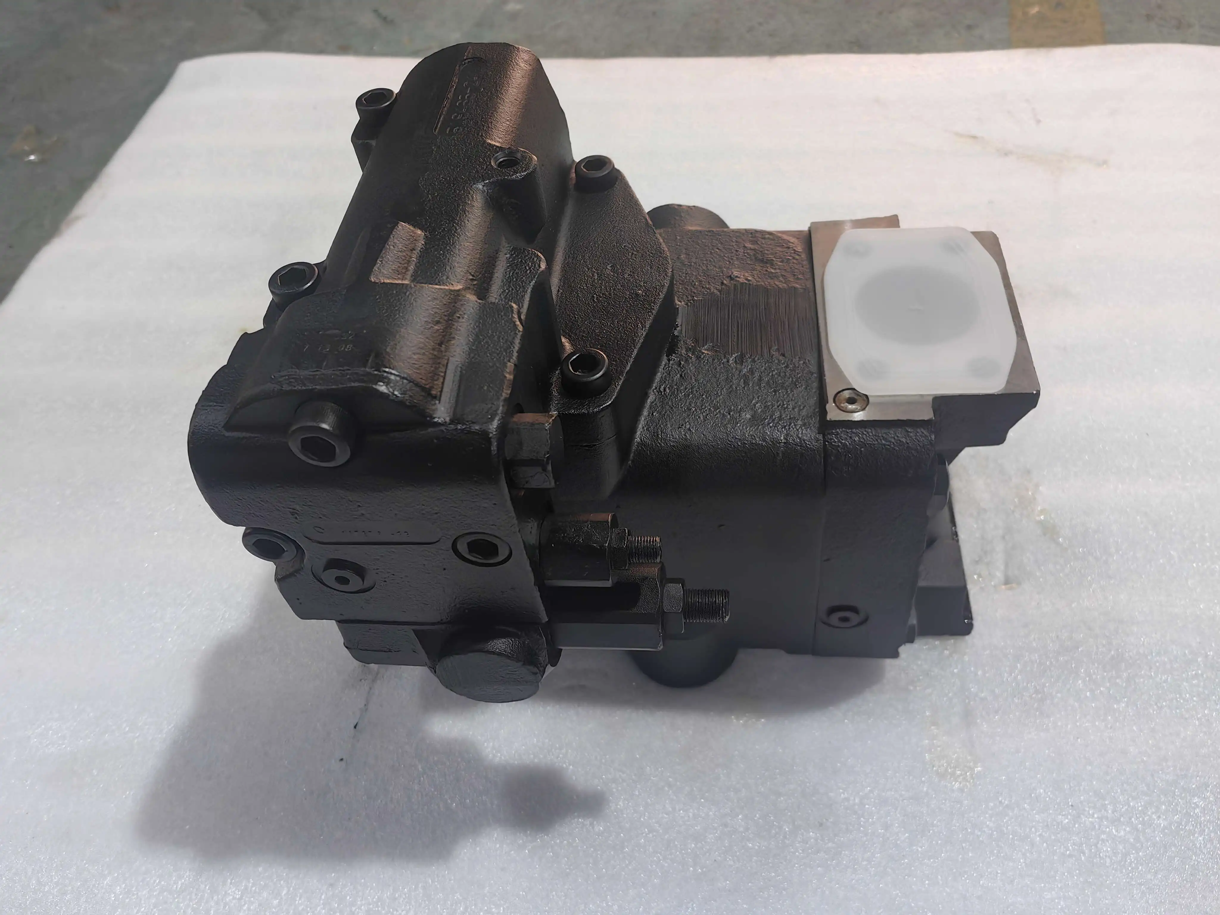
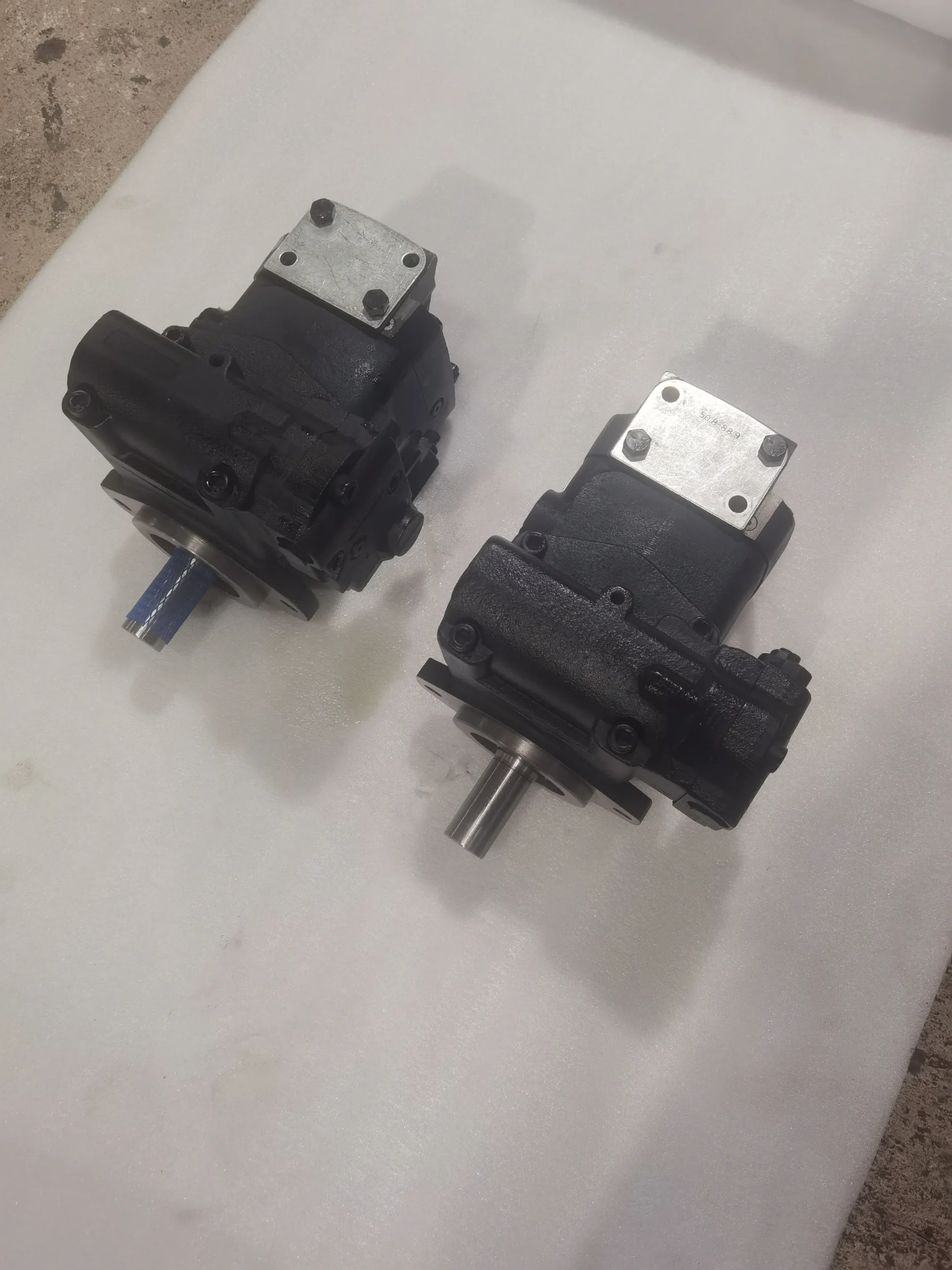
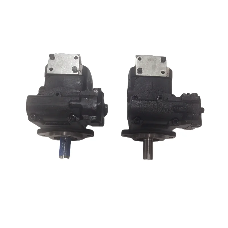
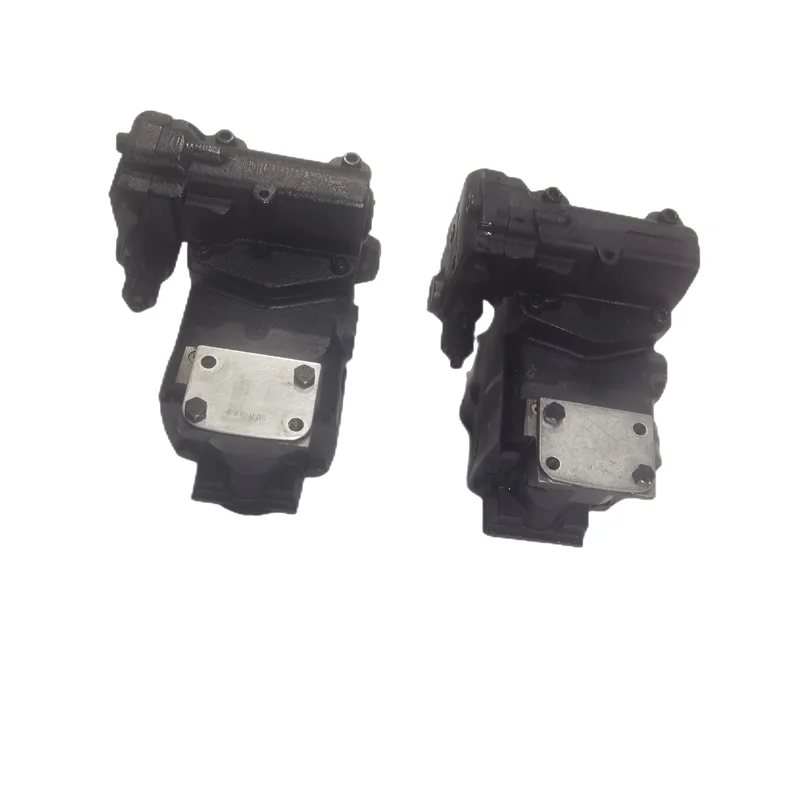
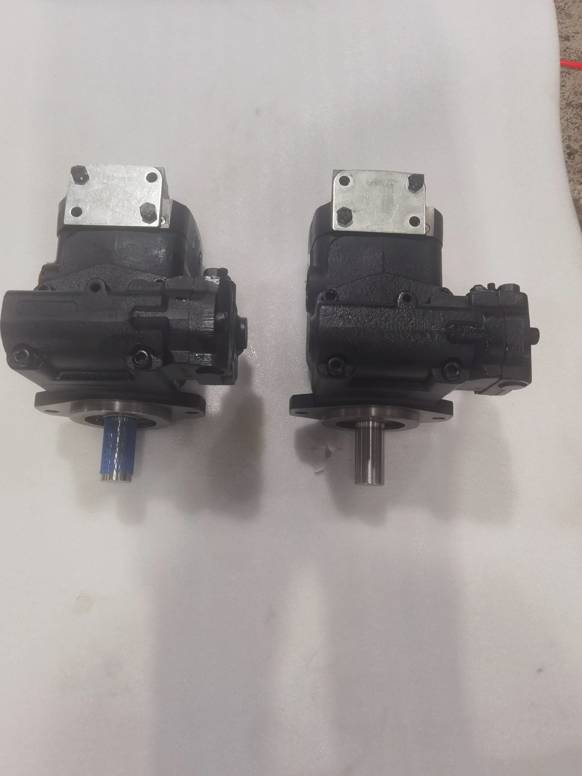
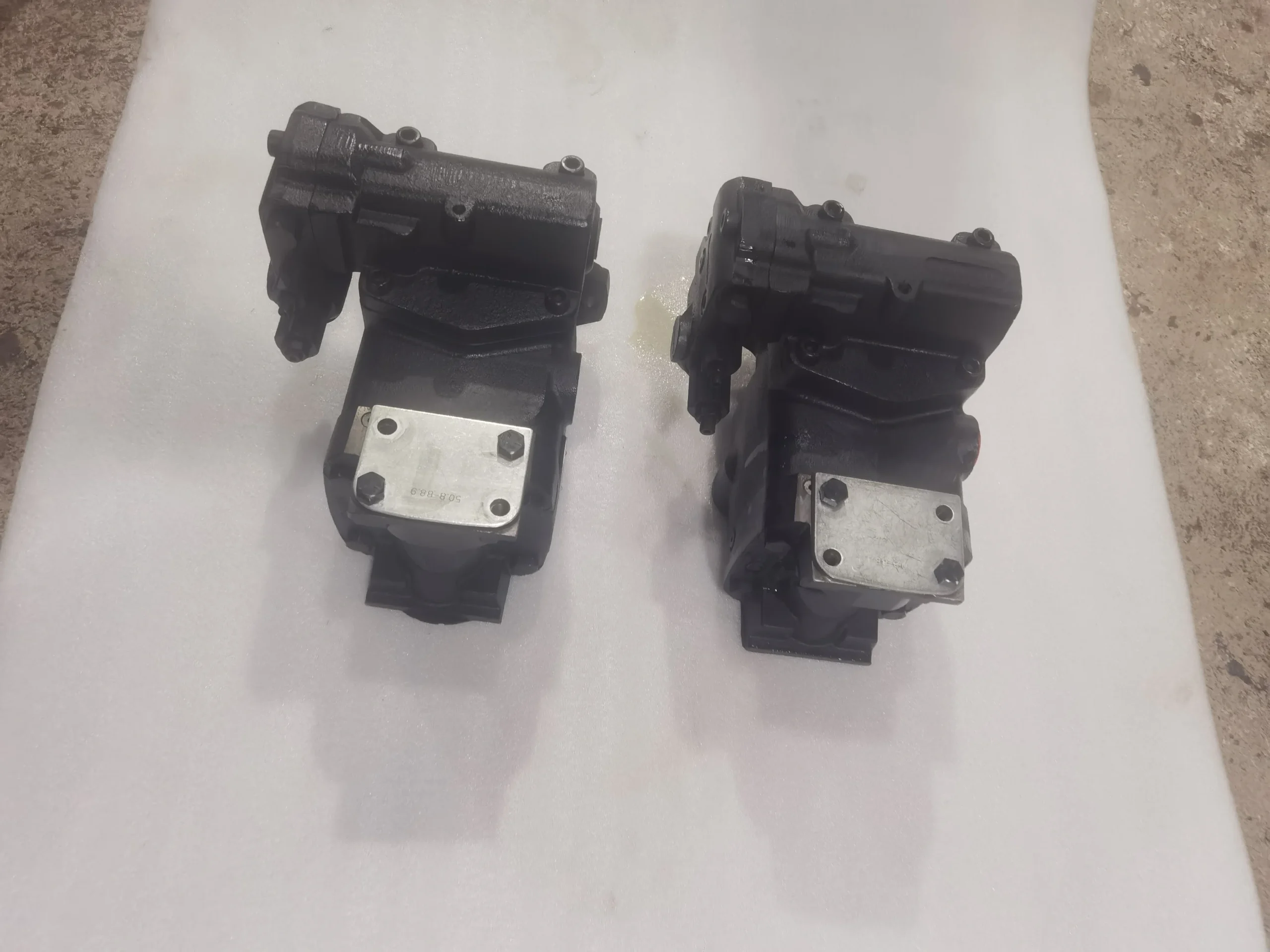
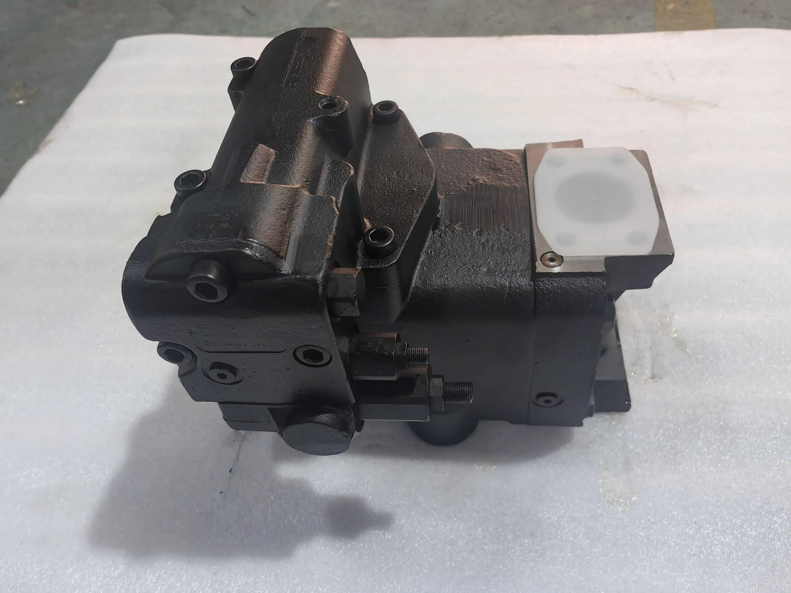
This plunger pump is of axial variable type, with a rated displacement of 150 cubic centimeters per revolution (the “150” in the model corresponds to the core displacement parameter). The volumetric efficiency shall not be less than 95%, and the total efficiency shall not be less than 91%. The continuous working pressure is 350 bar, and the short-term peak pressure is 380 bar (with a cumulative duration not exceeding 50 hours). The rated speed is 1500 revolutions per minute, the maximum speed is 2000 revolutions per minute, and the minimum stable speed is 500 revolutions per minute. When the speed fluctuation is ≤±2%, the flow stability error is ≤1.2%. Under rated working conditions, the maximum output flow is approximately 225 liters per minute, corresponding to a continuous output power of about 131 kilowatts.Structurally, it adopts a high-strength aluminum alloy shell and is equipped with a cylinder block assembly featuring 7 hard alloy coated plungers inside. The output shaft has a diameter of 60 millimeters and can withstand a radial force of ≤2000 Newtons and an axial force of ≤1200 Newtons. It is installed by flange, conforming to the common installation dimensions of large-scale construction machinery. The oil inlet is of G3 internal thread and the oil outlet is of G2½ internal thread. The overall weight is approximately 85 kilograms. Compatible with L-HM 46/68 anti-wear hydraulic oil. L-HV hydraulic oil can be selected for low-temperature working conditions. The working temperature range is from -15℃ to 90℃. The contamination degree of the oil should reach ISO 4406 16/13 grade, and the protection grade is IP67.
This plunger pump is of axial variable type, with a rated displacement of 150 cubic centimeters per revolution (the “150” in the model corresponds to the core displacement parameter). The volumetric efficiency shall not be less than 95%, and the total efficiency shall not be less than 91%. The continuous working pressure is 350 bar, and the short-term peak pressure is 380 bar (with a cumulative duration not exceeding 50 hours). The rated speed is 1500 revolutions per minute, the maximum speed is 2000 revolutions per minute, and the minimum stable speed is 500 revolutions per minute. When the speed fluctuation is ≤±2%, the flow stability error is ≤1.2%. Under rated working conditions, the maximum output flow is approximately 225 liters per minute, corresponding to a continuous output power of about 131 kilowatts.Structurally, it adopts a high-strength aluminum alloy shell and is equipped with a cylinder block assembly featuring 7 hard alloy coated plungers inside. The output shaft has a diameter of 60 millimeters and can withstand a radial force of ≤2000 Newtons and an axial force of ≤1200 Newtons. It is installed by flange, conforming to the common installation dimensions of large-scale construction machinery. The oil inlet is of G3 internal thread and the oil outlet is of G2½ internal thread. The overall weight is approximately 85 kilograms. Compatible with L-HM 46/68 anti-wear hydraulic oil. L-HV hydraulic oil can be selected for low-temperature working conditions. The working temperature range is from -15℃ to 90℃. The contamination degree of the oil should reach ISO 4406 16/13 grade, and the protection grade is IP67.
Ii. Working Principle
It adopts the axial plunger variable working principle. The core achieves energy conversion and precise flow regulation through the reciprocating motion of the plunger and the load-sensitive variable mechanism in coordination. Inside the pump body, the cylinder rotates synchronously with the transmission shaft. The fixed swash plate forms a rigid constraint on the end of the plunger through the sliding shoe, and the other end of the plunger is embedded in the cylinder body hole to form a closed oil cavity and is connected to the precision distribution plate. When high-pressure oil is distributed into the sealed oil chamber through the distribution plate, the oil pressure pushes the plunger to extend outward along the cylinder block hole. The end of the plunger slides along the curved surface of the swash plate and drives the cylinder block to rotate, thereby driving the output shaft to output torque. When the plunger rotates with the cylinder block to the oil return area, the swash plate compresses the plunger and retracts, reducing the volume of the oil chamber. The oil is then discharged through the distribution plate, completing the oil suction and discharge cycle.
The system pressure changes are detected in real time through the load-sensitive valve group, and the swash plate Angle is automatically adjusted to change the plunger stroke, achieving stepless control of the output flow from 0 to 100% : when the load increases, the pressure is synchronously increased and matched with the corresponding flow; when the load decreases, the displacement is automatically reduced to reduce energy consumption. The output torque is directly proportional to the working pressure, and the rotational speed is positively correlated with the input flow rate. The uniform distribution design of the 7 plungers ensures that the torque ripple rate is ≤5%, and the operational stability is excellent.
Iii. Product Features and Advantages
It has outstanding performance advantages. With a curved surface optimized swash plate and a precise flow distribution pair design, its volumetric efficiency is as high as over 95%, saving 15-20% energy compared to ordinary plunger pumps of the same specification. Under the large-displacement design, the flow pulsation rate is still ≤1.8%, and the operating noise at 1 meter is ≤85 decibels. The low-noise and stable characteristics are suitable for the requirements of large-scale systems. It has bidirectional rotation capability, with the consistency error of flow and pressure in forward and reverse rotation being ≤2%, and can be adapted to bidirectional drive scenarios. The efficiency remains above 90% within a wide speed range of 500 to 2000 revolutions per minute, adapting to load fluctuations in complex working conditions.
Structurally, the aluminum alloy shell achieves a balance between lightweight and high strength, reducing the weight by 18% compared to cast iron pumps of the same displacement. The plunger and sliding shoe are treated with plasma spraying tungsten carbide coating, which has a wear resistance far exceeding that of conventional materials, and the average mean time between failures is ≥ 25,000 hours. The modular valve group integrated design enables key components such as pressure compensation valves and load sensitive valves to be disassembled and assembled separately. During maintenance, there is no need to disassemble the core components of the pump body, increasing maintenance efficiency by 40%. Supports left and right rotation direction customization and multi-installation posture adaptation to meet the pipeline layout requirements of different equipment.
It has extremely strong environmental adaptability. It is equipped with an internal anti-cavitation oil suction structure and a low-pressure pre-filling device. The oil suction height can reach 600 millimeters, and it can stably suck oil without an auxiliary pump. It can be started without preheating in a low-temperature environment of -15℃, and the sealing parts can still maintain excellent performance under a high-temperature working condition of 90℃. With a protection grade of IP67, it can adapt to harsh outdoor working conditions such as dampness, dust, and splashing water. Its tolerance to oil contamination is superior to that of conventional plunger pumps, and the oil replacement cycle can be extended by 30%.
Iv. Usage Functions and Purposes
The core function is to efficiently convert the mechanical energy of the prime mover (engine, motor) into high-pressure hydraulic energy, providing a stable oil source with large flow for large-scale hydraulic systems. The flow is dynamically allocated on demand through load-sensitive variable mechanisms, precisely matching the compound action requirements of multiple actuating elements. It is equipped with dual safety functions of pressure cut-off and overheat protection. When the system pressure exceeds the limit, it automatically limits the displacement. When the oil temperature exceeds the limit, it triggers a warning to protect the pump body and pipelines from impact damage. It can achieve both forward and reverse oil supply, directly drive the actuator to act in both directions, and reduce the configuration cost of the system’s directional control valve.
It is widely applied in large high-pressure hydraulic systems: in the field of construction machinery, it serves as the main pump for large excavators, shield machines, and crawler cranes, driving core working devices such as booms, buckets, and telescopic booms. It is suitable for medium-sized and larger hydraulic presses and metallurgical steel rolling mills in the industrial field, providing high-pressure power for pressing, rolling and other processes. It is also used in the hydraulic circuits of mining crushing machinery, ship deck machinery, large injection molding machines and tunnel boring equipment.
V. Applicable Machines and Scenarios
In industrial scenarios, it is compatible with hydraulic presses over 5,000 tons (with a working pressure of 300-350 bar and a flow rate of 150-225 liters per minute), providing continuous high-pressure power for the pressing mechanism. The pressure compensation function ensures the forming accuracy of the workpiece. It is compatible with the roll adjustment system of metallurgical hot rolling mills (working pressure 320-350 bar), driving the roll down device. The load-sensitive feature enables the roll gap adjustment to respond quickly, ensuring the rolling accuracy. In large injection molding machines (with a working pressure of 280-320 bar), drive the clamping and injection systems, and the high-flow design is adapted to the demand for rapid mold closing.
In the context of construction machinery, it is compatible with the main working system of large excavators over 30 tons (working pressure 330-350 bar, flow rate 180-225 liters per minute), simultaneously driving the compound actions of the boom, bucket arm and bucket, ensuring uniform flow distribution and a response delay of no more than 0.1 seconds. Compatible with the shield machine propulsion system (working pressure 320-340 bar), it provides continuous and stable power for the propulsion cylinder, ensuring the continuity of tunnel construction with high reliability. In mining machinery, the drive system of the crushing hammer used in large crushers (working pressure 300-330 bar) features high wear resistance, making it suitable for dusty and dense working conditions.
Six. Similar models
Among different specifications and models of the same series, PVG-125-A1UV-RGFS-P-1NNSN has a displacement of 125 cubic centimeters per revolution, a continuous working pressure of 350 bar, a flow rate of approximately 188 liters per minute, a power of 109 kilowatts, and a weight of about 72 kilograms. It is suitable for medium high-pressure systems. The PVG-180-A1UV-RGFS-P-1NNSN has a displacement of 180 cubic centimeters per revolution, a continuous working pressure of 330 bar, a flow rate of approximately 270 liters per minute, a power of 157 kilowatts, and a weight of about 98 kilograms. It is suitable for super-large hydraulic systems.
Among the same type but different series, PVG-150-P1UV-RGFS-P-1NNSN is a constant power variable type, with a constant power output that is suitable for the collaborative working conditions of multiple actuators. It is suitable for equipment such as concrete pump trucks and bridge erection machines. PVG-150-M1UV-RGFS-P-1NNSN is a manual variable type. The flow rate can be adjusted through a mechanical handle, making it suitable for simple high-pressure systems that do not require automatic control. There is also a cast iron shell reinforced type, with the continuous working pressure increased to 380 bar, suitable for scenarios such as ultra-high pressure test benches and heavy forging equipment.
PVV-540-B2BV-RSFY-V-S50SA
PVM-130-A2UV-RSFY-P-1NNSN
PVWH-25-RSAY-C2SN-450C
PVWJ-130-AlUV-LSAY-P-1NNNN
PVWJ-098-AlUV-LSAY-P-1NNNN
PVWJ-076-AlUV-LSAY-P-1NNNN
PVWW-34-AlUV-LSAY-CN-NN
PVWJ-011-A1UV-RSAY-P-1NNN
PVV-250-BIUV-RSFY-F-100SB
PVWJ098-A1UP-RDFS-P-1NN/KNN-CP
PVG-130-F1UV-LGFY-P-1NNNN
PVK-140-A1UV-RDFS-P-1NNSN-CP/133
PVV-250-B1BV-RSFY-P-1NNSN
PVV-250-B1BV-LDFY-P-1NNSN-CP
PVG-100-F1UV-RGFK-P-INN/G047SN/B27
PVWJ-098-AIUP-RDFS-P-1NN/KNN-CP
PVWJ-011-A1UV-RGAY-P-1NNSN
PVV-250-B1UV-RSFY-F-100SB
PVV-250-B1UV-V-S25SA/147
PVK-140-A1UV-RDFS-P-1NNSN-CP/217
PVWH-15-LDFY-CNSNTH-05
16PUPVM98/75-ZJ200
PVWW-34-LSAY-CN-NNNN
PVG100E1UVRGFKP-1NN/GO47SN/751
PVG-075-F1UV-LSFY-P-1NNSN-NN
PVM-046-A1UB-RSFY-P-1NNNN
PVV-540-B2BV-RSFY-V-S50SA
PVWJ-064-A1UV-RSFY-P2NNSN/0279
PVWJ-064-A1UV-RSFY-P2NNSN/0279
PVG-100-F1UV-RGFK-P-1NN/G047SN/827
PVWH-25-RSAY-C2SN-450C
PVG-100-F1UV-LDFY-P-1NNSN-CP
PVG-100-F1UV-LDFY-P-1NNSN-CP
PVG-100-F1UV-LDFY-P-1NNSN-CP
PVG-130-F1UB-LSFY-P-1NNNN
PVG-130-F1UV-RDFZ-P-1NNSN-CN
PVG-130-F1UV-LGFK-P-1NN/FNN
PVG-130-F1UV-RGFK-P-1NN/H100SN-NN
PVG-130-F1UV-RDFZ-P-1NNNN
PVG-130-F1UV-LDFY-P-1NN/H050NN-CP
PVG-100-F1UV-LDFY-P-1NNSN-CP
PVG-100-FIUV-LGFZ-P-1NNSN-NN
PVG-048-F1UV-LGFY-N-1NNNN-AA/05
PVG-100-F1UV-LGFY-N-20RSA
PVG-075-F1UV-LSFY-P-1NNSN-NN
PVG-075-F1UV-RDFY-N-1NNNN-AA/05Vii. Precautions for Use
When installing, it is necessary to ensure that the flatness of the installation plane is ≤0.05 mm, the roughness is ≤Ra3.2, and the coaxiality of the pump shaft and the drive shaft is ≤0.08 mm. Elastic couplings should be used for connection, and rigid connection is strictly prohibited. The suction pipe is selected as a short straight pipe with an inner diameter of ≥80 millimeters and a length of no more than 1.5 meters. A 120-mesh high-pressure filter is installed. The distance between the suction port and the bottom of the oil tank is ≥300 millimeters, and the suction resistance is ≤0.02 megapascals to prevent cavitation. The drain pipe should be connected to the oil tank separately, with a back pressure of no more than 0.1 megapascals. It must not be mixed with the return pipe. Before installation, it is necessary to confirm that the rotation direction is consistent with the equipment requirements to avoid installing it in the wrong direction and thus failing to supply oil.
PVG-100-F1UV-LDFY-P-1NNSN-CP
PVG-100-F1UV-LDFY-P-1NNSN-CP
PVG-130-F1UB-LSFY-P-1NNNN
PVG-130-F1UV-RDFZ-P-1NNSN-CN
PVG-130-F1UV-LGFK-P-1NN/FNN
PVG-130-F1UV-RGFK-P-1NN/H100SN-NN
PVG-130-F1UV-RDFZ-P-1NNNN
PVG-130-F1UV-LDFY-P-1NN/H050NN-CP
PVG-100-F1UV-LDFY-P-1NNSN-CP
PVG-100-FIUV-LGFZ-P-1NNSN-NN
PVG-048-F1UV-LGFY-N-1NNNN-AA/05
PVG-100-F1UV-LGFY-N-20RSA
PVG-075-F1UV-LSFY-P-1NNSN-NN
PVG-075-F1UV-RDFY-N-1NNNN-AA/05Vii. Precautions for Use
When installing, it is necessary to ensure that the flatness of the installation plane is ≤0.05 mm, the roughness is ≤Ra3.2, and the coaxiality of the pump shaft and the drive shaft is ≤0.08 mm. Elastic couplings should be used for connection, and rigid connection is strictly prohibited. The suction pipe is selected as a short straight pipe with an inner diameter of ≥80 millimeters and a length of no more than 1.5 meters. A 120-mesh high-pressure filter is installed. The distance between the suction port and the bottom of the oil tank is ≥300 millimeters, and the suction resistance is ≤0.02 megapascals to prevent cavitation. The drain pipe should be connected to the oil tank separately, with a back pressure of no more than 0.1 megapascals. It must not be mixed with the return pipe. Before installation, it is necessary to confirm that the rotation direction is consistent with the equipment requirements to avoid installing it in the wrong direction and thus failing to supply oil.
Before starting, check the oil level in the oil tank (which should be more than 200 millimeters above the suction port), fill the pump with clean and anti-wear hydraulic oil, and manually rotate the pump 3 to 4 times to confirm there is no jamming. After confirming the correct rotation direction through jog start-up, run it no-load for 15 minutes until the oil temperature rises above 35℃. Then gradually load it, with each pressure increase not exceeding 50 bar and an interval of no less than 5 minutes. Sudden loading to the rated pressure is strictly prohibited. During operation, monitor the oil temperature (normal 45-70℃, maximum not exceeding 90℃) and pressure (not exceeding 350 bar). If abnormal noise, vibration or leakage exceeds 2 milliliters per hour, stop the machine immediately for inspection.
In terms of maintenance, check the oil level, oil temperature and sealing condition every 800 hours. Check the filter and replace the filter element every 2000 hours. When the oil contamination level exceeds the standard, replace the oil immediately and thoroughly clean the system. Disassemble and inspect the wear of the plunger, sliding shoe and distribution plate every 3,000 hours. Replace the sealing parts in time if they are found to be aged or damaged. Hydraulic oils of different brands must not be mixed. In cold regions, the oil should be preheated to above 10℃ before starting. When compatible with water glycol medium, special sealing parts need to be replaced.
It is strictly prohibited to start or operate without oil. Even short-term dry running (more than 3 seconds) can cause sintering damage to the plunger and cylinder block. It is prohibited to operate simultaneously at the highest pressure and the highest rotational speed for a long time. The cumulative duration of short-term peak pressure shall not exceed 50 hours. Before shutting down, the load should be unloaded to low pressure (≤50 bar) and run for 5 to 8 minutes. Only when the oil temperature drops below 60℃ should the power be cut off. For short-term storage (≤30 days), the oil port should be sealed and the vehicle should be turned by hand once a month. For long-term storage (>30 days), anti-rust oil should be injected, and anti-rust grease should be applied to the output shaft. The anti-rust condition should be checked every quarter. Before reusing, replace the sealing parts and conduct a 3-hour no-load test run.