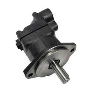
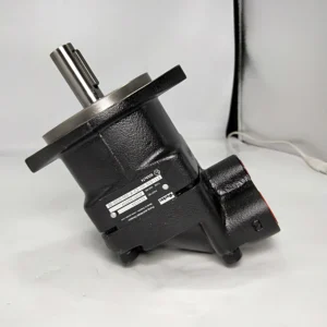
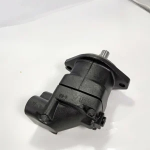
Product Overview
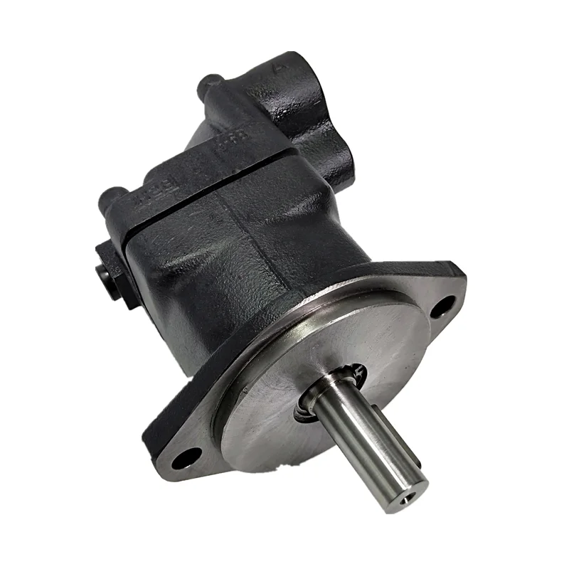
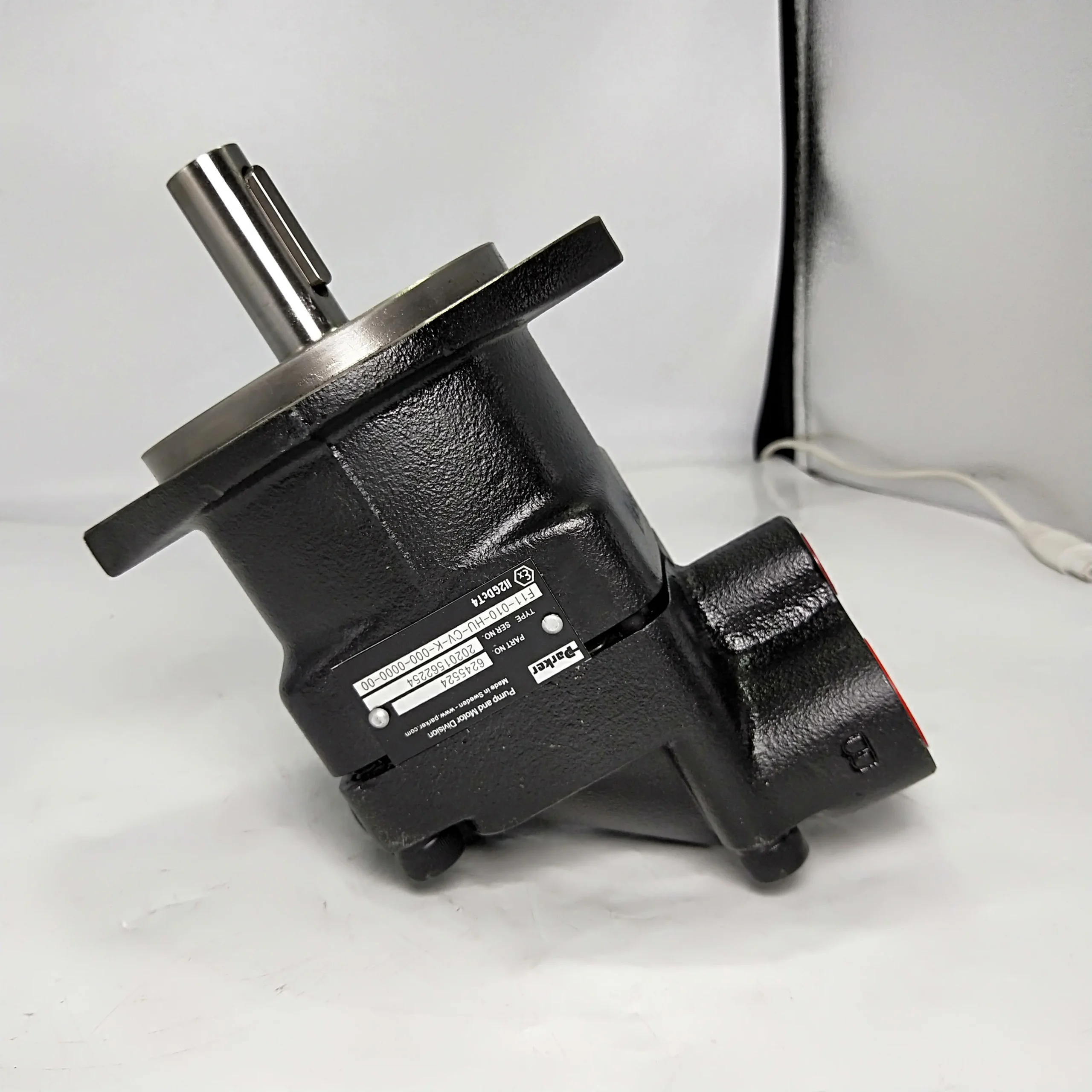
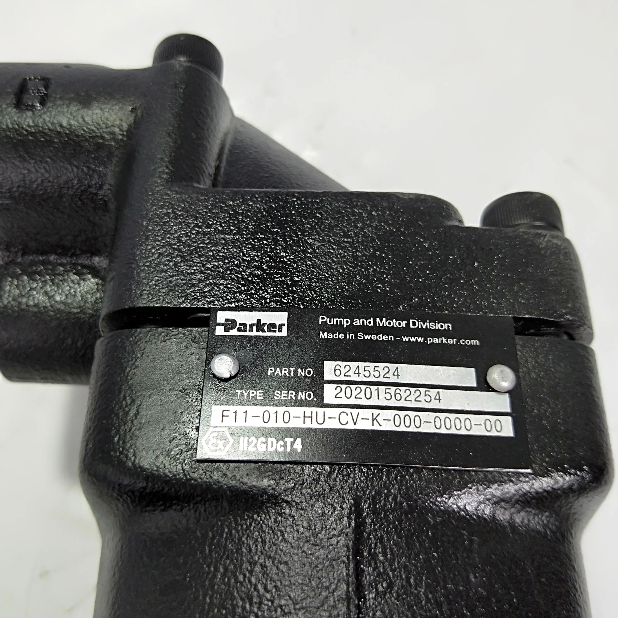
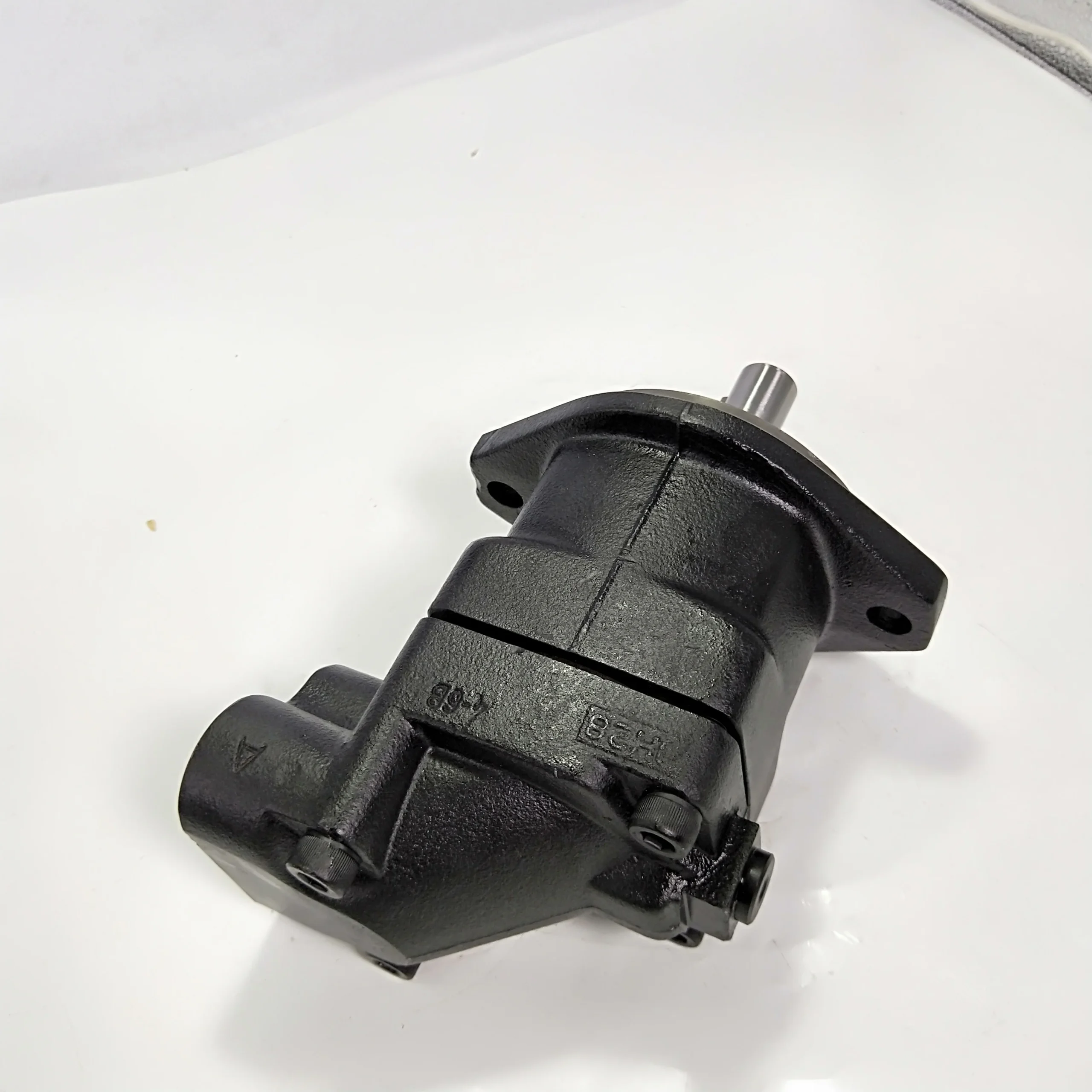
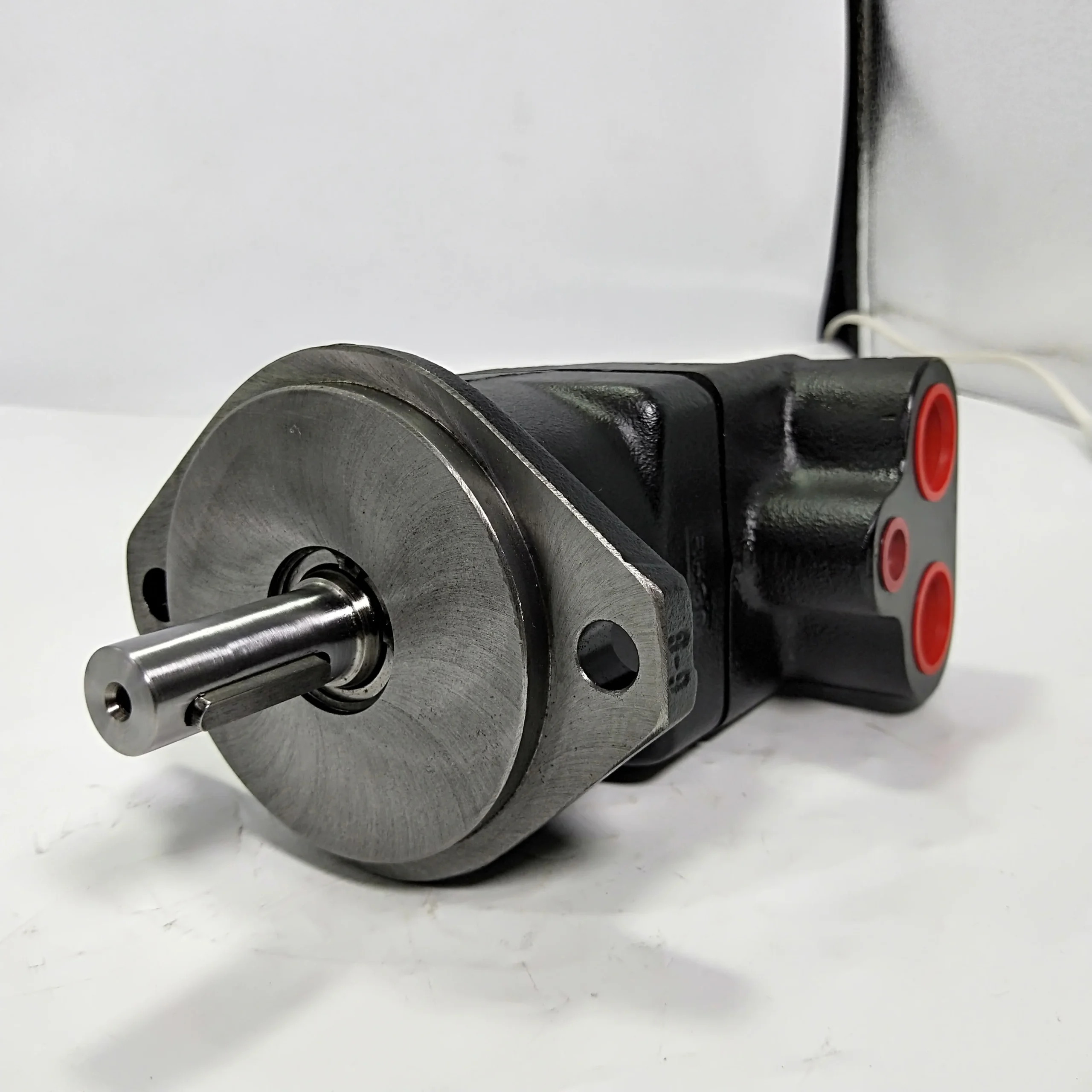
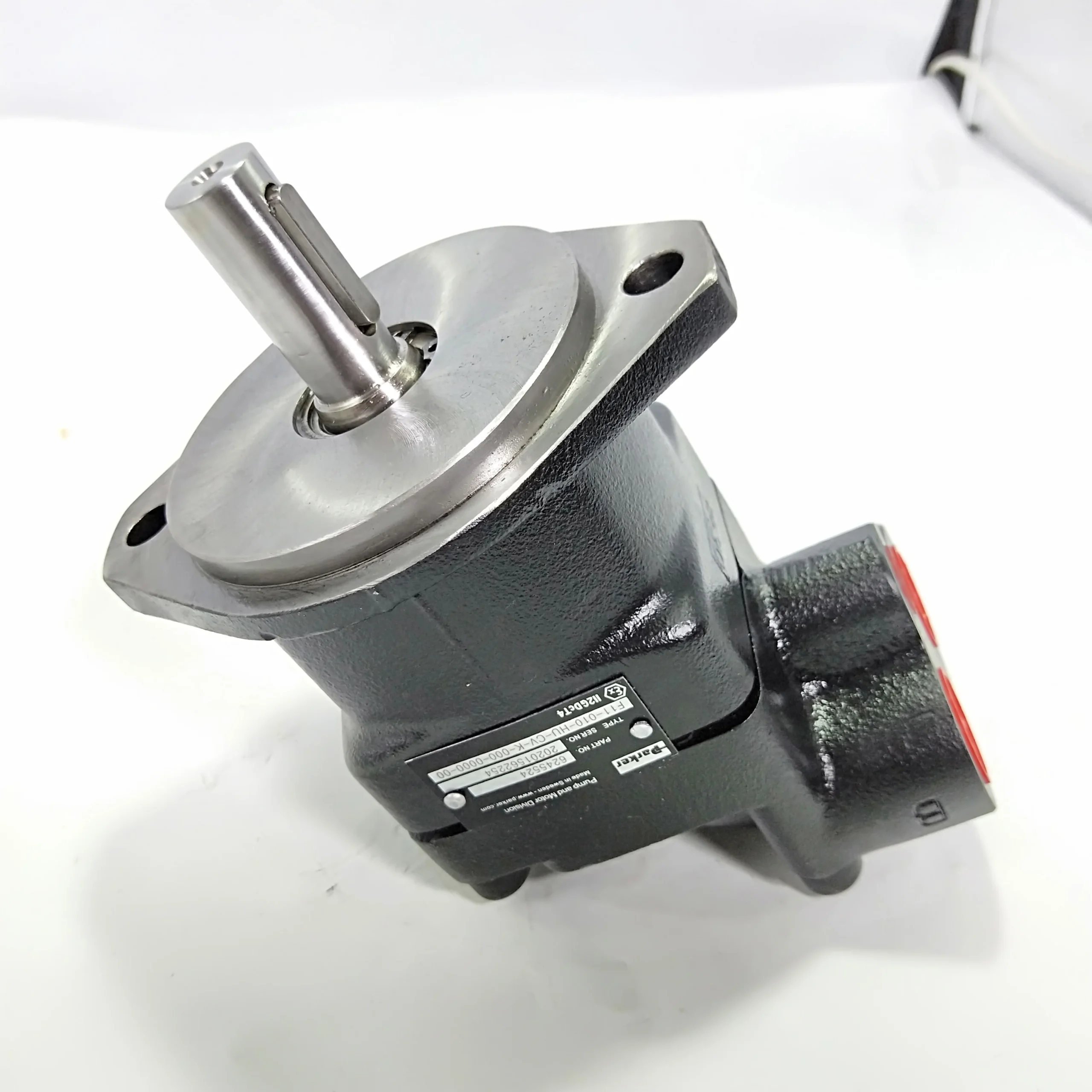
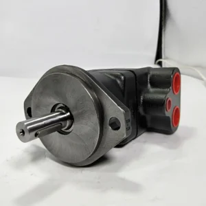
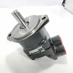
The F11-010-MB-CV-K-209 is a standard configuration model within the Parker Hannifin F11 Series of bent axis fixed displacement axial piston motors, originating from the Swedish VOAC (Volvo Hydraulics) product line acquired by Parker in the 1990s. The F11 Series employs a unique spherical piston concept, 40° bent axis angle design, laminated piston rings, and a timing gear mechanism, achieving operating pressures up to 420 bar (6,090 psi) and speeds up to 14,000 rpm, with displacements covering 4.9 to 242 cm³/rev — a global benchmark for high-speed, high-pressure hydraulic transmission.
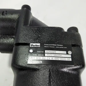
The model code F11-010-MB-CV-K-209 follows the Parker standard coding convention: F11 designates the product series; 010 indicates the frame size (9.8 cm³/rev); MB specifies the mounting flange and shaft configuration (CETOP flange, metric keyed shaft); CV denotes the control type; K indicates the seal type; and 209 specifies the special configuration code (fluorocarbon rubber high-pressure shaft seal). The motor is manufactured to original Parker specifications with 100% drop-in interchangeability, requiring no modification to mounting interfaces, port positions, or hydraulic connections. Every unit undergoes 100% simulated operating condition testing at the factory, including rated pressure loading, volumetric efficiency verification, seal integrity assessment, and low-speed smoothness validation prior to shipment.
Technical Specifications
F11-010-MB-CV-K-209:
Series / Type: Parker F11 Series bent axis fixed displacement axial piston motor
Displacement: 9.8 cm³/rev (0.598 cu in/rev)
Design: Bent axis, fixed displacement, 40° shaft-to-cylinder barrel angle
Rated continuous operating pressure: 350 bar (5,075 psi / 35 MPa)
Maximum intermittent pressure: 420 bar (6,090 psi / 42 MPa)
Peak pressure: 480 bar (6,960 psi)
Maximum continuous speed: 10,200 rpm
Maximum intermittent speed: 11,200 rpm
Minimum continuous speed: 50 rpm
Maximum continuous flow: 100 L/min (26 gpm)
Maximum intermittent flow: 110 L/min
Theoretical torque at 100 bar: 15.6 Nm
Direction of rotation: Bidirectional (either A or B port as inlet)
Mounting flange: CETOP 2-bolt flange
Output shaft: Ø20 mm metric keyed shaft
Ports: BSP threads
Shaft seal type: Fluorocarbon rubber high-pressure seal
Housing material: High-strength cast iron
Maximum case drain temperature: 115°C
Minimum operating temperature: -40°C
Moment of inertia: 0.39 x 10⁻³ kg·m²
Approximate weight: 6.5 kg
F11 Series displacement range (for reference):
F11-005: 4.9 cm³/rev, max continuous speed 12,800 rpm, theoretical torque 7.8 Nm, weight 4.7 kg
F11-006: 6.0 cm³/rev, max continuous speed 10,200 rpm, theoretical torque 9.5 Nm, weight 6.5 kg
F11-010: 9.8 cm³/rev, max continuous speed 10,200 rpm, theoretical torque 15.6 Nm, weight 6.5 kg
F11-012: 12.5 cm³/rev, max continuous speed 9,400 rpm, theoretical torque 19.8 Nm, weight 7.5 kg
F11-014: 14.3 cm³/rev, max continuous speed 9,000 rpm, theoretical torque 22.7 Nm, weight 7.5 kg
F11-019: 19.0 cm³/rev, max continuous speed 8,100 rpm, theoretical torque 30.2 Nm, weight 11 kg
F11-150: 150.8 cm³/rev, max continuous speed 3,600 rpm, theoretical torque 2.40 Nm/bar, weight approx. 60 kg
Note: Technical data above is sourced from Parker F11 Series official technical catalogue MSG30-8249/CN and authorized distributor technical data. The F11 Series covers displacements from 4.9 to 242 cm³/rev, with continuous working pressure of 350 bar, intermittent pressure of 420 bar, and maximum speed of 14,000 rpm. For precise technical specifications of the F11-010-MB-CV-K-209, always confirm against the official Parker technical manual or the product nameplate data.
Key Technical Advantages
1. Laminated Piston Ring Technology for High Volumetric Efficiency
The F11-010 employs Parker’s signature laminated piston ring construction, built from multiple thin steel laminations. The engineering significance of this design lies in its ability to adapt to micro-deformation of the cylinder bore under high pressure, maintaining consistent sealing contact. Under thermal cycling, the laminated construction offers thermal expansion compensation far superior to solid piston rings, effectively suppressing internal leakage with superior thermal shock resistance. This design maintains high volumetric efficiency across a wide temperature and pressure envelope, minimizing energy loss and heat generation from internal leakage.
2. 40° Bent Axis Design with Compact High Power Density
The F11-010 employs a 40° bent axis angle design, enabling high displacement density and torque output within an extremely compact envelope. Compared to swashplate designs, the bent axis architecture transmits piston force to the output shaft through a shorter, more direct path, yielding higher mechanical efficiency. The compact rotary group design enables the F11-010 to achieve 9.8 cm³/rev displacement capability and 350 bar working pressure in a unit weighing only approximately 6.5 kg, delivering a power-to-weight ratio that leads its class among comparable small-frame motors. Thanks to the spherical piston design and compact rotary group, the F11-010 tolerates extremely high shaft speeds — maximum continuous speed of 10,200 rpm.
3. Timing Gear Mechanism for High G-Force Tolerance
The F11-010 utilizes Parker’s unique timing gear mechanism that precisely synchronizes output shaft and cylinder barrel rotation. This timing gear design makes the motor extremely tolerant to high G-forces and torsional vibrations, making it ideally suited for installation on moving machinery subject to frequent shock and vibration loading. The precision meshing of the synchronizing gears ensures that piston reciprocation within the cylinder bores maintains correct phase relationship, preventing piston side-loading and seal failure caused by synchronization errors.
4. Heavy-Duty Dual Tapered Roller Bearings for High External Load Capacity
The F11-010 output shaft is supported by heavy-duty dual tapered roller bearings, capable of simultaneously accommodating significant radial and axial external loads. The engineering advantage of this bearing configuration lies in its ability to directly absorb radial forces generated by driven components (gears, sprockets, pulleys) without requiring a separate bearing support housing — simplifying system design and reducing installation costs. This characteristic is particularly important for drive applications with sprockets or gears directly mounted on the motor shaft. The motor features a simple and straightforward design with very few moving parts, ensuring high reliability and long service life.
Application Areas
Forestry equipment: Chain saw drives, feller bunchers, skidders, forwarders
Material handling: Deck cranes, hatch cover drives, skid steer loader travel drives
Construction equipment: Rotary drilling rig auxiliary drives, vibratory roller travel drives, excavator auxiliary systems
Oil & gas: Coil tubing units, frac trucks, nitrogen pumpers, drilling platform auxiliary drives
Agricultural machinery: Mowers, cutters, combine harvester auxiliary drives
Industrial drives: Aircraft test stands, constant tension winches, fan drives, dust collectors
Marine and offshore: Deck machinery, windlass drives, marine cranes
Expert Maintenance Tips
1. Fluid Cleanliness Management Is the Primary Task
The F11-010 operates with micron-level clearances between pistons and cylinder bores and between the valve plate and cylinder barrel face. Particulate contamination in hydraulic fluid is the leading cause of piston scoring and valve plate wear. Systems must be equipped with filtration rated to ISO 4406 18/16/13 or better. In high-contamination environments such as forestry or construction job sites, shorten fluid change intervals and increase filter replacement frequency accordingly.
2. Case Drain Flow as a Wear Monitoring Indicator
Case drain flow is a sensitive indicator of internal motor condition. Per Parker service manual procedure: run the unit at normal speed and pressurize the system to 150–200 bar, disconnect the drain line, and measure drain flow for one minute. Compare the measured value against Parker’s baseline specification for a new unit. A significant increase in drain flow may indicate piston-slipper wear or valve plate sealing degradation, warranting timely inspection. Install a spring-loaded check valve (1–3 bar) in the drain line to maintain correct case pressure and lubrication.
3. Pre-Start Case Filling and Air Purging
Before first startup after installation or repair, the motor case must be filled with clean hydraulic fluid through the highest case port until fluid overflows. The F11-010 bent axis architecture creates a complex internal case cavity geometry; starting an un-purged motor can cause dry friction damage to piston ball ends and socket bushings, leading to irreversible premature wear.
4. Laminated Piston Ring Replacement Criteria and Installation Points
Laminated piston rings are the critical sealing components affecting volumetric efficiency in the F11 Series. During teardown and repair, inspect the spherical piston rings for wear. Parker service manual specifies that piston rings with more than 50% wear on the spherical surface must be replaced. When installing new piston rings, ensure the ring gap position is correct and the lamination direction matches the original. Note: the old spherical piston ring version has been discontinued and must be replaced with the laminated version, along with the corresponding pistons. All shaft seals and O-rings should always be replaced during any teardown procedure.
5. Installation Alignment and Flange Tightening
The F11-010 uses CETOP standard flange mounting. During installation, verify that the output shaft is properly aligned with the mating component. While dual tapered roller bearings accommodate substantial external loads, installation misalignment will significantly shorten bearing life. Tighten mounting bolts in stages to the specified torque value, and re-check torque after 500 operating hours.
6. Restart Procedure After Extended Shutdown
If the motor has been idle for more than three months, manually rotate the output shaft to confirm freedom of movement, and inspect the case oil level and shaft seal for leakage before restarting. Extended shutdown can cause oil film drainage from piston-slipper interfaces, creating a dry-start risk. Before restarting, replenish clean hydraulic fluid through the case fill port and operate at low speed and reduced load for 10–15 minutes before returning to normal duty.