


51V110 & 51V160 Bent Axis Motor | Danfoss 51V Series | 48MPa 5600RPM
| Model Number | 51V110-1-RC8NTAC2NNX1 NNN 045AANN0023 |
|---|
SKU
N/A
Categories Hydraulic Motor, Piston Motor
Tags char-lynn motor, danfoss hydraulic motor, eaton hydraulic motor, gerotor motor, high speed hydraulic motor, hydraulic gear motor, hydraulic motor, hydraulic wheel motor, hydro motor, orbit hydraulic motor, parker hydraulic motor, parker motor, poclain hydraulic motor, sauer danfoss motor, staffa hydraulic motor
Product Description
Product Overview
The 51V110-1-RC8NTAC2NNX1 and 51V160RF1NHSA2BHE1NNN belong to the Danfoss Series 51/51-1 family of bent axis variable displacement piston motors, featuring spherical piston and bent axis construction. Manufactured to original technical standards with precision-matched critical components, these motors deliver true drop-in interchangeability with genuine Danfoss/Vickers units. Every motor undergoes 100% simulated operating condition bench testing before shipment, validating volumetric efficiency, pressure retention, and control response characteristics.
The Series 51/51-1 motors feature a large maximum/minimum displacement ratio of 5:1 and high output speed capabilities. SAE, cartridge, and DIN flange configurations are available. Motors normally start at maximum displacement, providing maximum starting torque for high-acceleration applications.
Technical Specifications
51V110-1-RC8NTAC2NNX1:
Series: 51V110-1
Motor Type: Bent Axis Variable Displacement Motor
Maximum Displacement (Vg max): 109.9 cm³/rev [6.71 in³]
Minimum Displacement (Vg min): 22.0 cm³/rev [1.34 in³]
Displacement Ratio: 5:1
Rated Pressure: 48 MPa (480 bar)
Peak Pressure: 51 MPa (510 bar)
Maximum Speed (at max displacement): 2800 rpm
Maximum Speed (at min displacement): 4500 rpm
Rated Flow: 308 L/min [81 US gal/min]
Maximum Flow: 396 L/min [105 US gal/min]
Maximum Corner Power: 492 kW [660 hp]
Weight (approx.): 44 kg [97 lb]
Mass Moment of Inertia: 0.0128 kgm² [0.3037 lb·ft²]
Control Type: Two-position control (N1NN)
Mounting: SAE 4-bolt flange per ISO 3019/1
Direction of Rotation: Bi-directional (CW/CCW)
51V160RF1NHSA2BHE1NNN:
Series: 51V160
Motor Type: Bent Axis Variable Displacement Motor
Maximum Displacement (Vg max): 160.9 cm³/rev [9.82 in³]
Minimum Displacement (Vg min): 32.2 cm³/rev [1.96 in³]
Displacement Ratio: 5:1
Rated Pressure: 48 MPa (480 bar)
Peak Pressure: 51 MPa (510 bar)
Maximum Speed (at max displacement): 2500 rpm
Maximum Speed (at min displacement): 4000 rpm
Rated Flow: 402 L/min [106 US gal/min]
Maximum Flow: 515 L/min [136 US gal/min]
Maximum Corner Power: 644 kW [864 hp]
Weight (approx.): 56 kg [123 lb]
Mass Moment of Inertia: 0.0234 kgm² [0.5553 lb·ft²]
Control Type: RF1 Proportional Control with Pressure Compensator
Mounting: SAE 4-bolt flange
Direction of Rotation: Bi-directional (CW/CCW)
Key Technical Advantages
1. Bent Axis Spherical Piston Design — High Volumetric Efficiency
The spherical piston and bent axis drive principle achieves near-contactless operation through hydrostatic pressure balancing between the piston and cylinder bore. This design substantially reduces friction losses, with volumetric efficiency exceeding 95% at rated conditions. The contact stress between the spherical piston head and drive plate is optimized through finite element analysis, ensuring structural integrity under high-pressure operation. Compared to swashplate designs, the bent axis configuration delivers higher power density and lower case heat generation at equivalent displacement.
2. 5:1 Large Displacement Ratio — Wide Speed Range
The Series 51/51-1 motors feature an industry-leading 5:1 maximum-to-minimum displacement ratio. The 51V110 displacement varies continuously from 22 to 109.9 cm³/rev, while the 51V160 covers 32.2 to 160.9 cm³/rev. This enables a single motor to cover a wide speed-torque envelope: maximum displacement for high torque during vehicle launch, shifting to minimum displacement for elevated speed during high-speed travel, significantly optimizing system energy utilization.
3. High-Pressure Capability — Harsh Environment Adaptability
With a rated pressure of 48 MPa and peak pressure of 51 MPa, these motors are engineered for heavy-duty continuous operation in construction machinery. The housing is cast from high-strength nodular iron and pressure-tested after precision machining, ensuring zero leakage and zero deformation at 510 bar peak pressure. The valve plate and cylinder block end faces undergo precision lapping and surface hardening to maintain stable hydrodynamic lubrication under high pressure differentials, suppressing wear.
4. Precision Matched-Lapping Process — Low Noise & Long Service Life
Critical kinematic pairs — including piston-cylinder bore, valve plate-cylinder block face, and drive plate-piston ball head — are manufactured using matched-lapping processes with clearances controlled at the micron level. This ensures uniform oil film stiffness across all kinematic pairs, effectively suppressing pressure and flow pulsation for low-noise operation. Simultaneously, precision fitment substantially reduces localized contact stress, extending bearing and kinematic pair service life.
5. Integrated Pressure Compensator — System Overload Protection
The RF1 control configuration on the 51V160 incorporates a pressure compensator. When system pressure reaches the set threshold, the compensator automatically reduces motor displacement to limit torque output, preventing system overload. The compensator features a low pressure rise (short ramp), ensuring optimal power utilization throughout the entire displacement range. The compensator functions in both motor and pump modes, and a defeat option is available to disable compensator override in pump mode.
Application Areas
Construction Machinery: Excavator travel drives, rotary drilling rig swing drives, roller vibration drives
Mining Equipment: Underground LHD loaders, drill rig travel systems
Agricultural Machinery: Combine harvester travel drives, tractor hydrostatic transmissions
Material Handling: Reach stackers, container handlers travel drives
Specialty Vehicles: Street sweepers, snow removal vehicles hydrostatic drive systems
Industrial Equipment: Winch drives, injection molding machine clamp drives
Expert Maintenance Tips
Installation Notes:
The motor housing must always remain filled with hydraulic fluid. Installation position is discretionary, but the housing must be primed through the case drain port before first startup.
Main pressure ports use SAE flange connections; remaining ports are SAE straight-thread O-ring boss. Tighten to specified torque values.
Closed-circuit systems must incorporate an independent braking system. Do not rely on the hydrostatic transmission for holding braking.
Operating & Maintenance Guidelines:
Select hydraulic fluid viscosity based on operating temperature, maintaining optimum viscosity range (VG46 or VG55 recommended). Case drain temperature, affected by pressure and speed, is always higher than circuit temperature. System temperature at any point must not exceed 118°C.
Periodically monitor case drain flow. Abnormal increases typically indicate accelerated internal wear.
Verify pressure compensator settings at regular intervals using calibrated gauges at the provided gauge ports.
Replace hydraulic fluid and filters after the first 500 hours of operation; thereafter, determine change intervals based on oil analysis results.
After extended storage, manually rotate the shaft to confirm freedom of movement and bleed air from the highest point of the housing before restart.


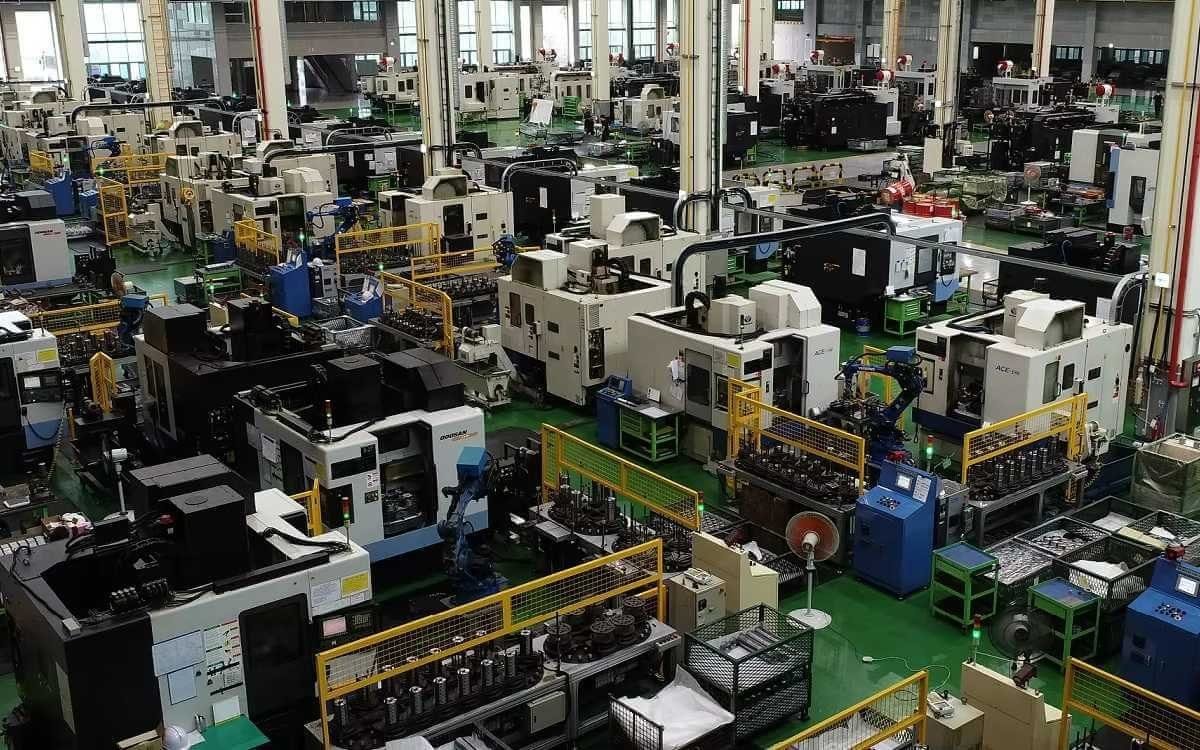
Company Profile


Frequently Asked Questions
1.What ls our Main Products?
1.Hydraulic pump
2.Hydraulic valve
3.Hydraulic motor
4.Hydraulic cylinder
5.Hydraulic parts
2. What about the MOQ?
3.What are your advantages?
- Adhere to quality first.
- Support customization, ODM & OEM service.
- 1-year warranty and complete after-sales support.
- Safe and fast shipping worldwide.
- 24-hour online service for your inquiries.
4.Are you a manufacturer? What’s your delivery time?
Yes, we are a manufacturer with our own factory.
Common models are in stock, and orders are usually shipped within 1–3 days.
5.Which payment methods are accepted?
We accept T/T, L/C, PayPal, VISA, Western Union, Apple Pay, Google Pay, Afterpay (Clearpay), Klarna, and Trade Assurance.
For full orders: 30% deposit, balance before shipment.
For small/sample orders: full payment in advance.
6.How will you deliver my goods?
We offer flexible shipping options: DHL, UPS, FedEx, TNT, EMS, as well as air or sea freight.
All deliveries ensure door-to-door fast and safe service.
7.How do you inspect and guarantee your products?
All products are tested before shipment to ensure perfect working condition.
We offer a 12-month warranty — if a product fails due to quality issues, we provide free spare parts or repair support.
8.What about after-sales service?
If you encounter any problem during use, please contact your sales manager or our support team at any time.
We will respond quickly and help solve the issue efficiently.
9.What are your main applications?
- Hydraulic systems
- Agricultural machinery
- Construction machinery
- Automobile industry
- Local distributors and maintenance centers
10.Can I get a discount for bulk orders?
Yes. We offer competitive wholesale prices and try our best to give benefits to long-term partners.
Shoot Us An Email
Professional Manufacturer