


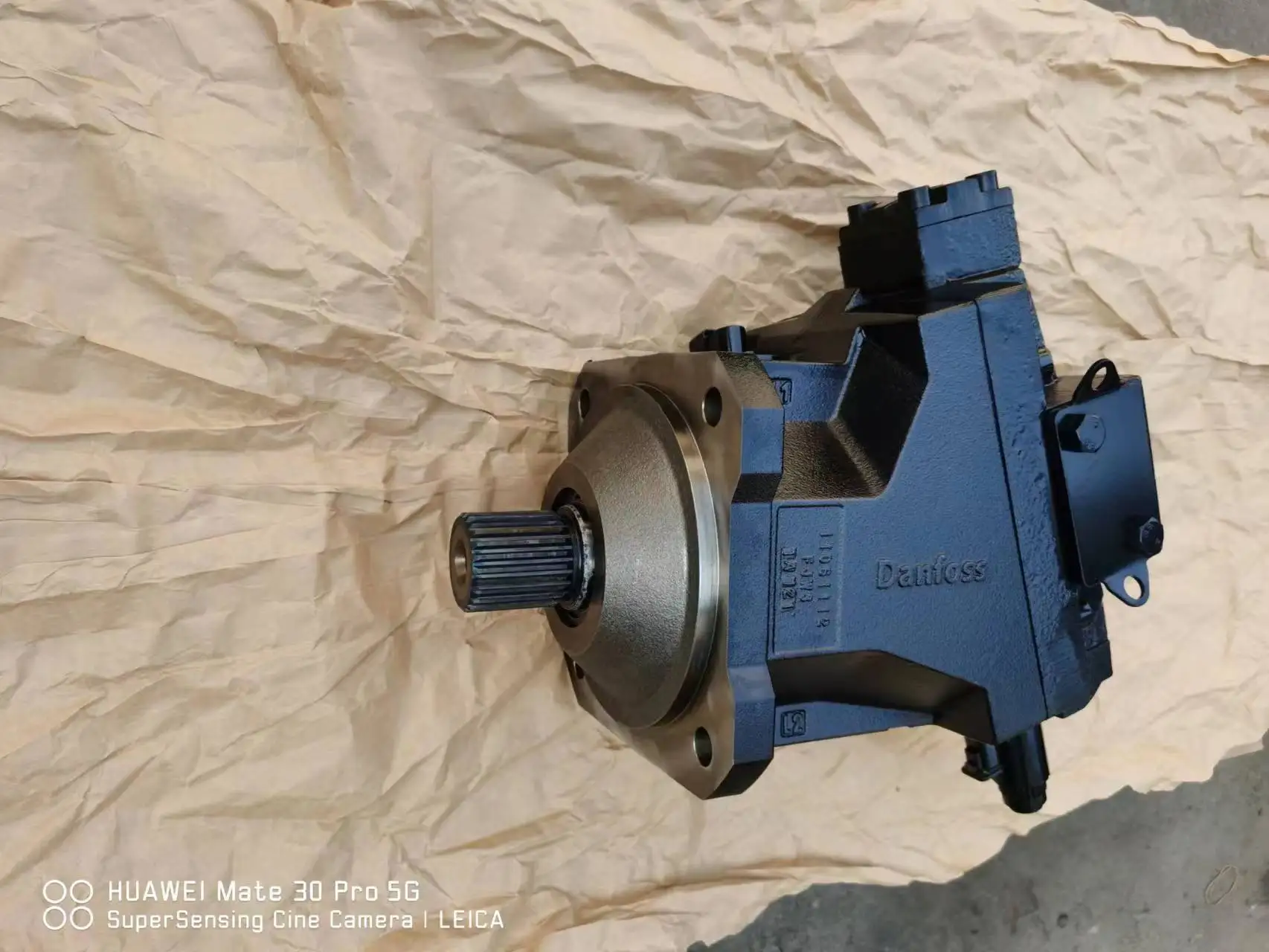
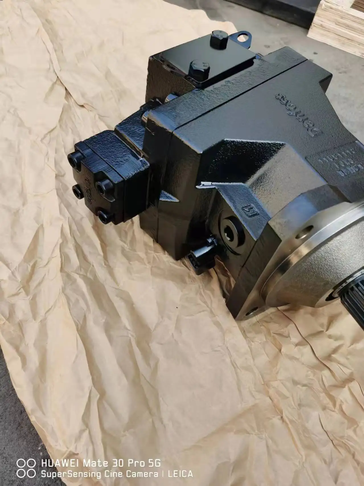




H1B080AE2AANBTBDNJNNA10NN032Z00NNN Danfoss Motor | 450 Bar
| Model Number | H1B080AE2AANBTBDNJNNA10NN032Z00NNN |
|---|
SKU
N/A
Categories Hydraulic Motor, Piston Motor
Tags char-lynn motor, danfoss hydraulic motor, eaton hydraulic motor, gerotor motor, high speed hydraulic motor, hydraulic gear motor, hydraulic motor, hydraulic wheel motor, hydro motor, orbit hydraulic motor, parker hydraulic motor, parker motor, poclain hydraulic motor, sauer danfoss motor, staffa hydraulic motor
Product Description
Product Overview
The H1B080AE2AANBTBDNJNNA10NN032Z00NNN is an 80 cm³/rev displacement model from Danfoss’ H1B series of bent-axis axial piston variable motors. The H1B series is the successor to Danfoss’ proven Series 51 bent-axis motors, featuring a 32° maximum bent-axis angle, spherical piston design and integrated housing construction. With a maximum-to-minimum displacement ratio of 5:1 and maximum displacements from 60 to 250 cm³/rev, the series is ideal for medium-to-high power mobile hydraulic closed-circuit systems.
H1B series motors are designed primarily for closed-circuit hydrostatic transmission systems, combining with H1 series pumps for efficient hydraulic power transfer and control. The series is equally applicable to open circuits, expanding to high-power open-circuit applications including drilling, crushing, forestry and heavy-duty excavator attachments when combined with counterbalance valves. H1B motors deliver greater overall efficiency in a compact package, with rated output speeds ranging from approximately 2,350 rpm at maximum displacement to 4,300 rpm at zero displacement.
The model code breaks down as follows: H1B identifies the H1 series bent-axis variable motor; 080 denotes the 80 cm³/rev displacement; A indicates H1B product version A; E2 is the control type (electric proportional, 12V/24V depending on configuration); AA is the port configuration code (inch per ISO 11926-1); N is an additional option; B is the compensator and brake pressure defeat configuration; TA is the endcap type and ports (for 2-position and pressure compensator controls, axial ports ISO 6162 Type 1 metric); DN is the shaft and speed ring configuration (27 tooth 16/32 pitch ANSI 92.1 1970 class 5, no speed ring); JN is the sensor and additional options; N is the loop flushing shuttle system (no loop flushing function); A10 is the loop flushing relief valve (10 l/min, non-adjustable, 16 bar cracking pressure); NN is the special hardware features (standard hardware feature, proportional standard); 032 is the minimum displacement setting (32 cm³/rev); Z is the maximum displacement (100% maximum, non-adjustable); 00 is the pressure compensator override setting (no override function); NNN is the paint and nametag (Danfoss nametag).
Every H1B080 unit undergoes 100% simulated operating-condition bench testing prior to shipment. Mounting flange, shaft end and port dimensions comply with SAE/DIN standards and are identical to the original Danfoss H1B080, ensuring true drop-in interchangeability with zero modification required.
Technical Specifications
H1B Series Frame Size Specifications:
H1B060: Max displacement 60 cm³/rev (3.66 in³/rev), min displacement 12 cm³/rev (5:1 ratio), rated output speed (max displacement) 2,350 rpm, rated output speed (zero displacement) 4,300 rpm, system pressure (delta) 450 bar, peak pressure 480 bar
H1B080 (This Model): Max displacement 80 cm³/rev (4.88 in³/rev), min displacement 16 cm³/rev (5:1 ratio), rated output speed (max displacement) ~3,600 rpm, system pressure (delta) 450 bar, peak pressure 480 bar, weight ~34.8 kg, max flow 328 l/min
H1B110: Max displacement 110 cm³/rev (6.71 in³/rev), min displacement 22 cm³/rev (5:1 ratio), system pressure (delta) 450 bar, peak pressure 480 bar
H1B160: Max displacement 160 cm³/rev (9.76 in³/rev), min displacement 32 cm³/rev (5:1 ratio), system pressure (delta) 450 bar, peak pressure 480 bar
H1B210: Max displacement 210 cm³/rev (12.81 in³/rev), min displacement 42 cm³/rev (5:1 ratio), rated output speed (20% displacement) 3,850 rpm, system pressure (delta) 450 bar
H1B250: Max displacement 250 cm³/rev (15.25 in³/rev), min displacement 50 cm³/rev (5:1 ratio), system pressure (delta) 450 bar, peak pressure 480 bar
H1B080AE2AANBTBDNJNNA10NN032Z00NNN Additional Specifications:
Model Code: H1B080AE2AANBTBDNJNNA10NN032Z00NNN
Type: Bent-axis axial piston variable motor, spherical piston design
Maximum Displacement: 80 cm³/rev (4.88 in³/rev)
Minimum Displacement Setting: 32 cm³/rev
Displacement Ratio: 5:1
Maximum Bent Axis Angle: 32°
System Pressure (Delta): 450 bar (6,527 psi)
Peak Pressure (Absolute): 480 bar (6,960 psi)
Rated Output Speed (Max Displacement): ~3,600 rpm
Maximum Speed: 4,000 rpm
Control Type: E2 electric proportional, de-energized = minimum displacement
Pressure Compensator Override: None (00 code)
Endcap Type and Ports: Endcap for 2-position and pressure compensator controls, axial ports ISO 6162 Type 1 (metric)
Mounting Flange: SAE-flange motor housing (ISO 3019/1), no speed sensor port
Shaft Configuration: 27 tooth 16/32 pitch ANSI 92.1 1970 class 5 splined shaft, no speed ring
Loop Flushing: No loop flushing function (N code), with loop flushing relief valve (10 l/min, 16 bar cracking pressure)
Rotation: Bi-directional (clockwise / counter-clockwise)
Weight: ~34.8 kg
Temperature Range: -40°C to +115°C
Hydraulic Fluid: Mineral oil (ISO VG46/68), synthetic oil, water glycol
Circuit Type: Closed circuit (primary), open circuit (with counterbalance valve)
Original Design: Danfoss Power Solutions, Denmark/USA
Key Technical Advantages
1. 32° Bent-Axis Angle with Spherical Piston Design for High Startup Torque and High Power Density
The H1B080 employs Danfoss H1B series’ signature 32° maximum bent-axis angle with spherical piston design, with the cylinder block angled relative to the output shaft and spherical pistons acting against a thrust plate through piston rings. The bent-axis architecture delivers high torque at startup with favorable starting efficiency. Optimized surface finish combined with high spring rate and best-in-class components provides high-speed capability at minimum angle for maximum performance. The bent-axis design has the shortest unit lengths in its class, with one-piece housing construction further improving structural rigidity and dynamic torque capabilities.
2. High Pressure Capability — 450 Bar Delta, 480 Bar Peak
The H1B080 supports 450 bar balanced delta pressure with 480 bar peak absolute pressure, enabling adaptation to high power-density closed-circuit hydraulic systems. This pressure rating enables machines to operate at high power, increasing effectiveness. System pressure capability is class-leading among comparable bent-axis motors, offering significant advantages in travel drive and tool drive applications requiring high torque density.
3. 5:1 Wide Displacement Ratio and Zero Displacement Function for Full-Range Efficiency
The H1B080 modulates between 80 cm³/rev maximum and 32 cm³/rev minimum displacement, achieving a 5:1 ratio. The maximum-displacement mode delivers maximum torque for heavy-duty startup and grade climbing; the minimum-displacement mode significantly increases speed capability for light-load high-speed cruising. The H1B series’ zero displacement function allows the output shaft to idle, further increasing equipment transport speed and enabling efficient switching between working and transport modes.
4. E2 Electro-Proportional Control with Pressure Compensator Override for Precise Displacement Modulation
The H1B080 is configured with E2 electric proportional control, where de-energized status automatically returns the motor to minimum displacement for system safety. All controls utilize internally supplied servo pressure, which may be overridden by a pressure compensator functioning in both motor and pump modes, enabling optimal power utilization. The pressure compensator features low pressure rise, ensuring optimal power utilization throughout the motor’s entire displacement range.
5. 100% Simulated Load Testing & Drop-In Interchangeability
Each H1B080 unit is bench-tested under simulated operating conditions prior to dispatch, covering pressure cycling, displacement response and thermal variation. Mounting flange, shaft end and port dimensions comply with SAE/DIN standards, matching the original Danfoss H1B080 exactly, enabling direct replacement without pipework or interface modification.
Application Areas
The H1B080 is deployed across demanding closed-circuit and open-circuit hydrostatic transmission applications:
Agriculture: combine harvester hydrostatic travel drives, self-propelled sprayers, tractor front axles
Construction: road rollers, wheel loaders, asphalt pavers, road building equipment
Material Handling: rough terrain forklifts, telescopic handlers, crane slewing drives
Forestry: forwarder travel drives, feller buncher saw head drives
Mining & Drilling: drill head drives, crusher drives, heavy-duty excavator attachments
Offshore: oil and gas equipment drives, deck machinery
Industrial: closed-circuit hydrostatic transmission systems, winch drives
Expert Maintenance Tips
1. Control Signal Calibration and Displacement Verification: The E2 electric proportional control requires control signal calibration after installation to confirm minimum displacement position (32 cm³/rev) and maximum displacement position match the technical manual. Pilot control pressure should remain stable within the technical manual specified range with ±1 bar variation. If displacement response exhibits lag or drift, inspect the control spool for sticking and the pilot circuit for air entrainment. The pressure compensator override function is not activated in this configuration (00 code); contact Danfoss for override-enabled configurations.
2. Loop Flushing Valve Maintenance: This model is configured with an A10 loop flushing relief valve at 10 l/min flow and 16 bar cracking pressure. Periodically inspect its operating condition. Insufficient flushing flow causes circuit oil temperature rise and contamination accumulation, affecting motor life. Inspect flushing valve flow and pressure settings every 1,000 hours. The loop flushing shuttle system (N code) is not configured in this model—verify the loop flushing scheme during system design.
3. Splined Shaft and Coupling Inspection: The H1B080 is configured with a 27 tooth 16/32 pitch ANSI 92.1 1970 class 5 splined shaft. Periodically inspect output splined shaft wear; excessive spline clearance causes abnormal vibration and noise. Coupling alignment deviation must not exceed 0.05 mm to prevent abnormal bearing wear and shaft seal leakage. Apply appropriate grease to spline connections during installation.
4. Oil Cleanliness and Temperature Control: Maintain system oil cleanliness at ISO 4406 18/16/13 or better. Case drain temperature is affected by pressure and speed and is always higher than circuit temperature—system temperature must not exceed 115°C at any point. Replace hydraulic oil and filter after the first 500 hours, then follow a 2,000-hour or annual replacement cycle. Refer to the Danfoss technical manual for operating viscosity range; VG 46 is recommended at 60°C operating temperature.
5. Drain Line Management and Housing Priming: The drain port must return to the reservoir independently—housing back pressure must not exceed 2 bar. The drain line end must remain submerged to prevent air ingestion. Fill the housing with clean hydraulic oil before first startup. After extended shutdown, fill the housing again before restarting. External shaft seal accessibility simplifies seal inspection and replacement.
6. Periodic Piston Group and Bent-Axis Bearing Inspection: The H1B080’s spherical pistons, piston rings and bent-axis bearings are primary wear components. Inspect spherical piston-to-cylinder bore clearance, piston ring wear and bent-axis bearing clearance every 2,000 hours. Abnormal efficiency loss, noise or vibration requires immediate shutdown and service. Use Danfoss original specification parts when replacing piston groups to ensure fit accuracy and assembly torque per technical manual requirements.


Company Profile

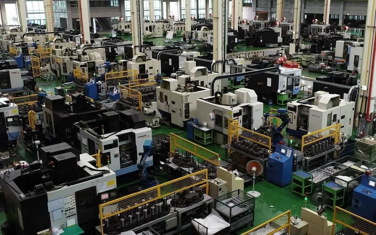

Frequently Asked Questions
1.What ls our Main Products?
1.Hydraulic pump
2.Hydraulic valve
3.Hydraulic motor
4.Hydraulic cylinder
5.Hydraulic parts
2. What about the MOQ?
3.What are your advantages?
- Adhere to quality first.
- Support customization, ODM & OEM service.
- 1-year warranty and complete after-sales support.
- Safe and fast shipping worldwide.
- 24-hour online service for your inquiries.
4.Are you a manufacturer? What’s your delivery time?
Yes, we are a manufacturer with our own factory.
Common models are in stock, and orders are usually shipped within 1–3 days.
5.Which payment methods are accepted?
We accept T/T, L/C, PayPal, VISA, Western Union, Apple Pay, Google Pay, Afterpay (Clearpay), Klarna, and Trade Assurance.
For full orders: 30% deposit, balance before shipment.
For small/sample orders: full payment in advance.
6.How will you deliver my goods?
We offer flexible shipping options: DHL, UPS, FedEx, TNT, EMS, as well as air or sea freight.
All deliveries ensure door-to-door fast and safe service.
7.How do you inspect and guarantee your products?
All products are tested before shipment to ensure perfect working condition.
We offer a 12-month warranty — if a product fails due to quality issues, we provide free spare parts or repair support.
8.What about after-sales service?
If you encounter any problem during use, please contact your sales manager or our support team at any time.
We will respond quickly and help solve the issue efficiently.
9.What are your main applications?
- Hydraulic systems
- Agricultural machinery
- Construction machinery
- Automobile industry
- Local distributors and maintenance centers
10.Can I get a discount for bulk orders?
Yes. We offer competitive wholesale prices and try our best to give benefits to long-term partners.
Shoot Us An Email
Professional Manufacturer