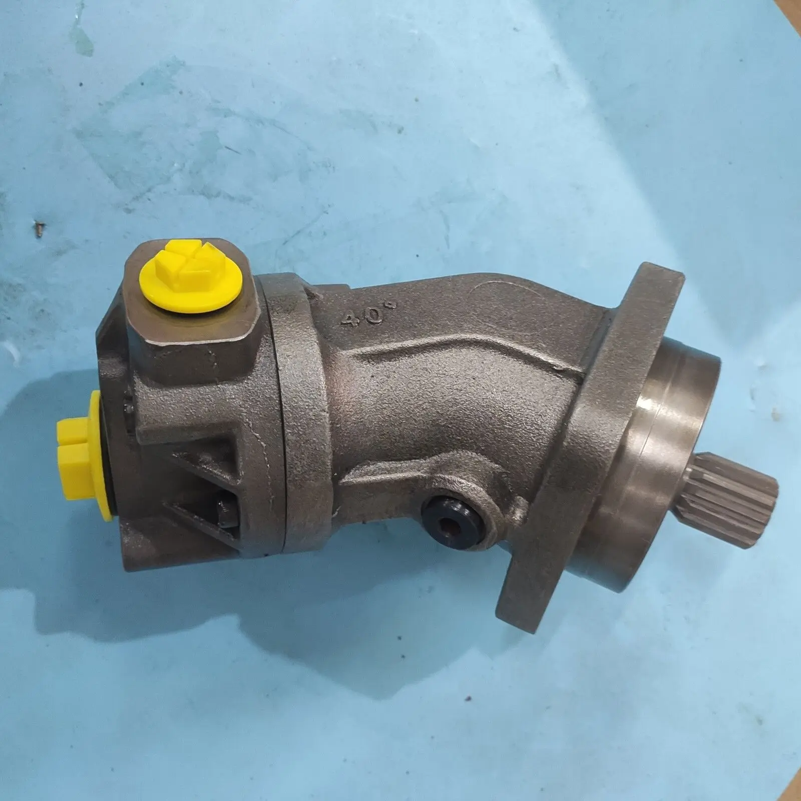
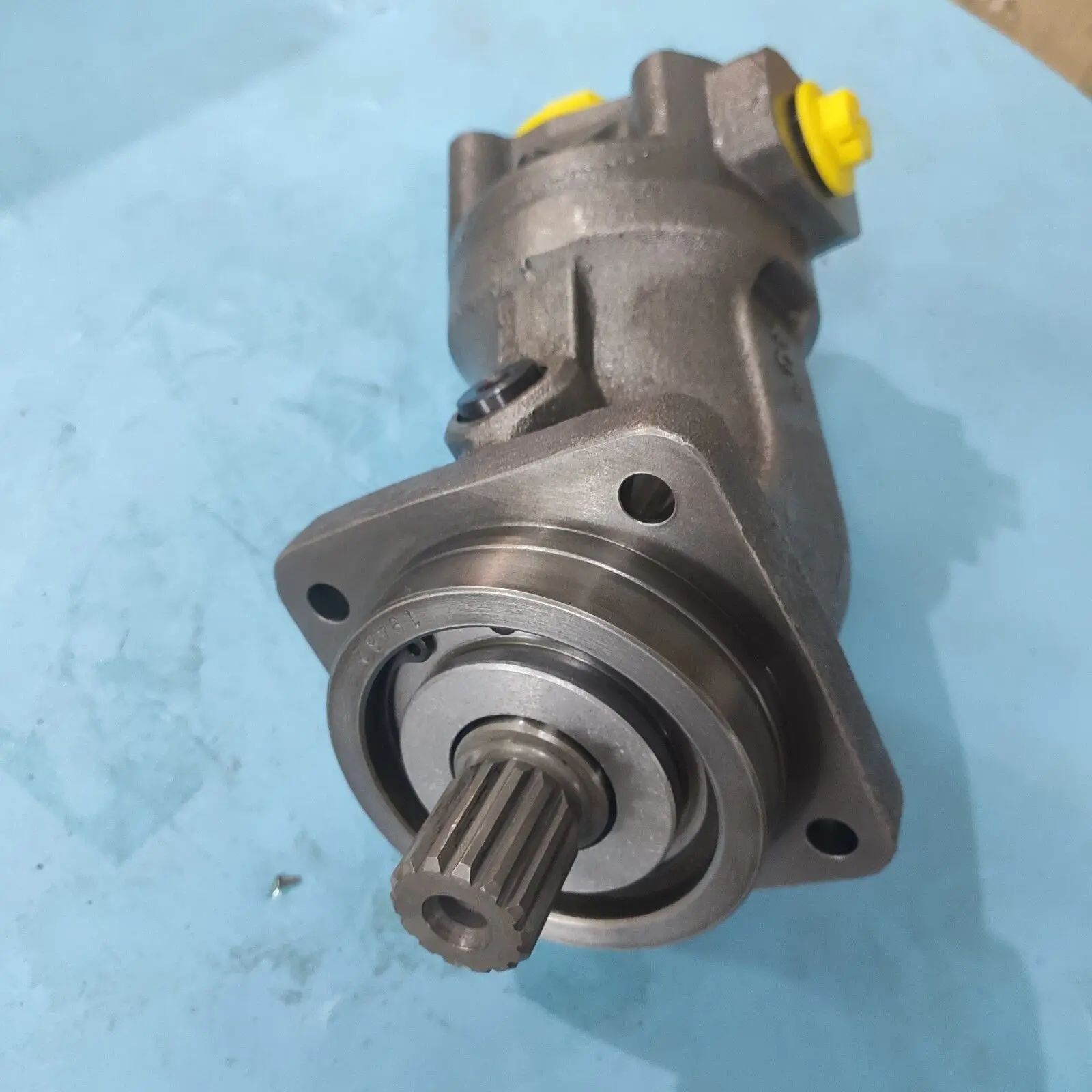
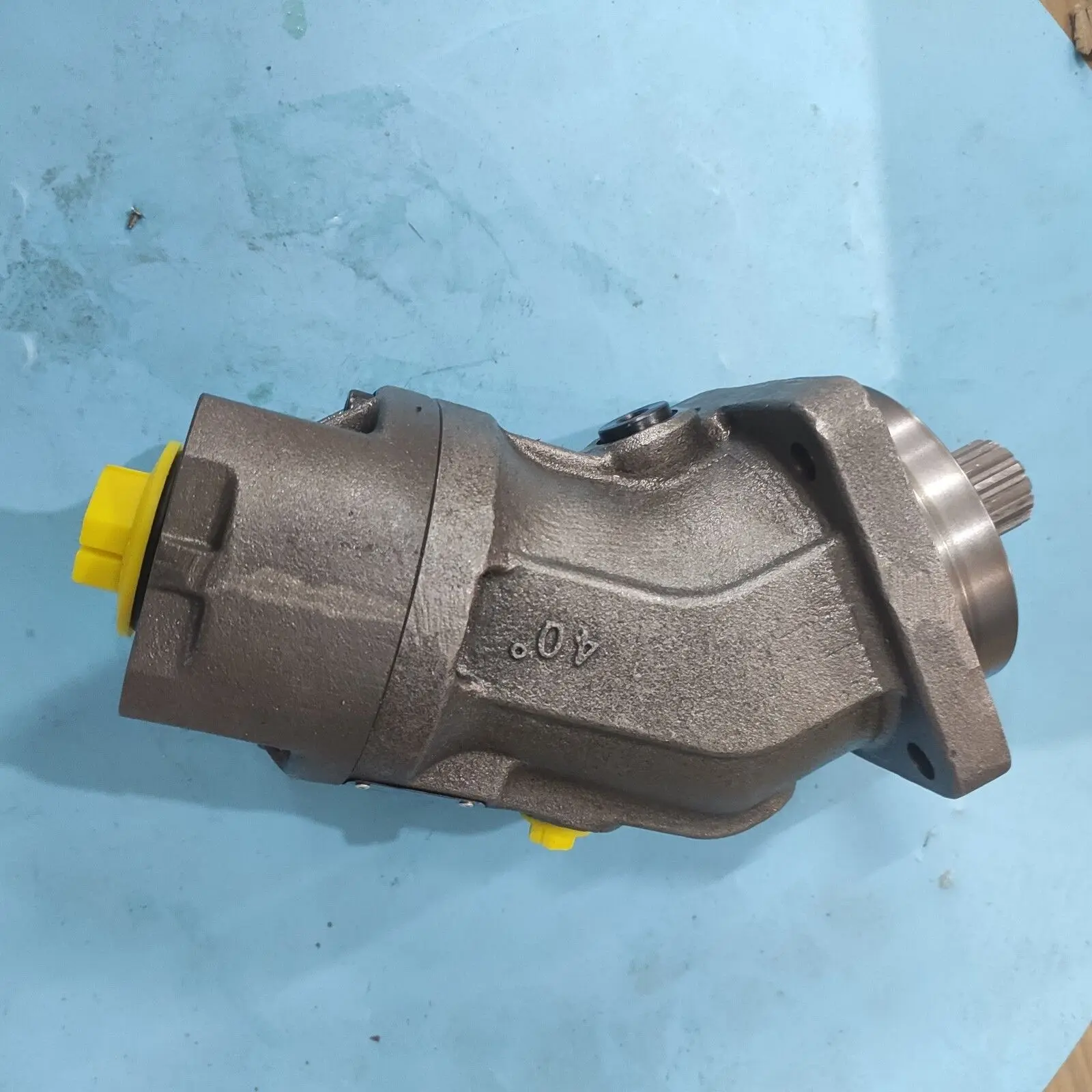
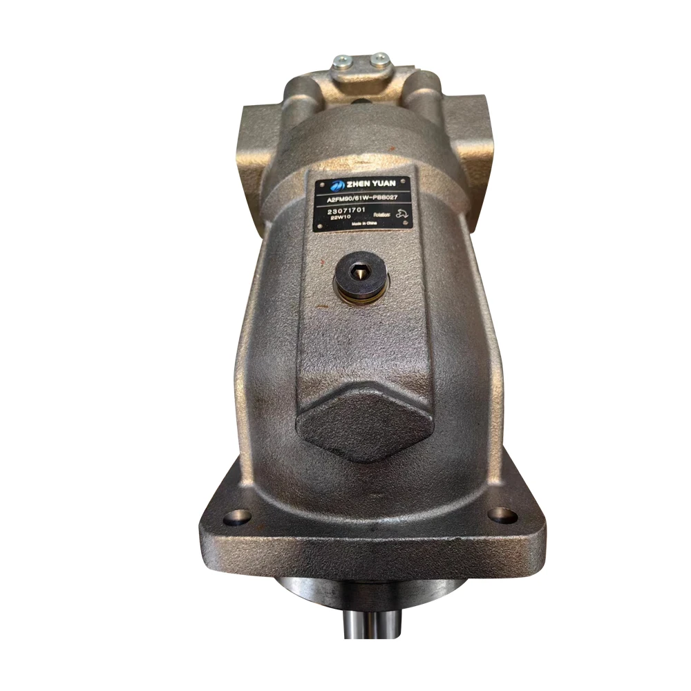
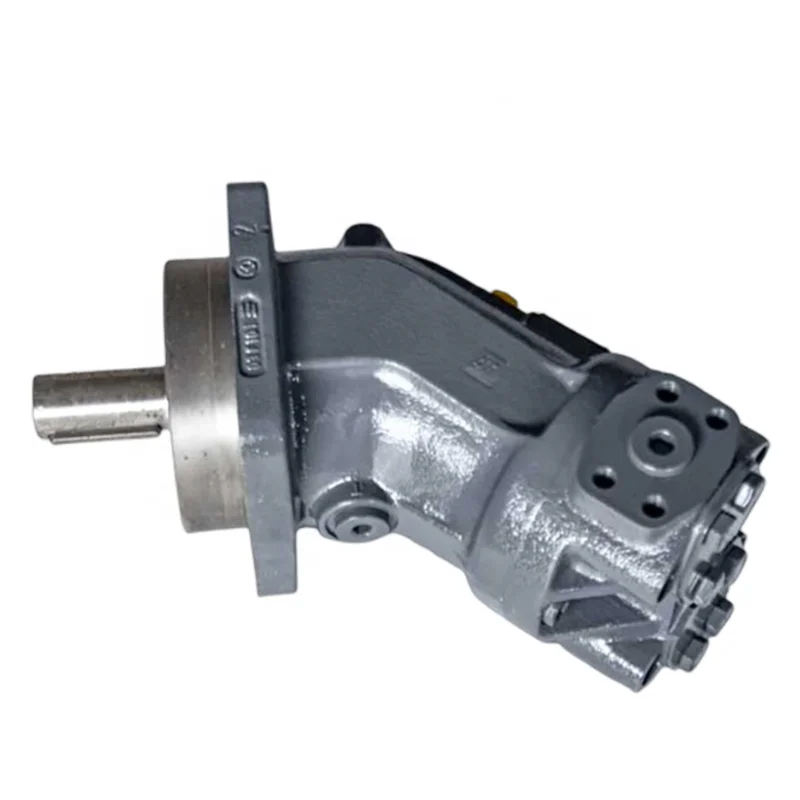
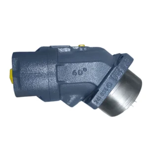
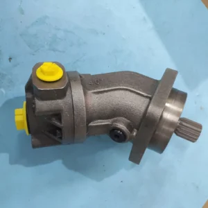
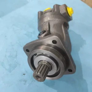
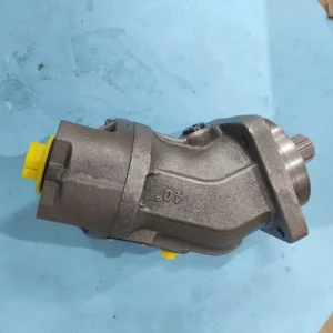
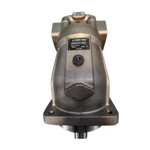
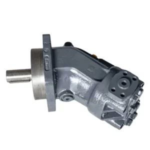
Product Overview
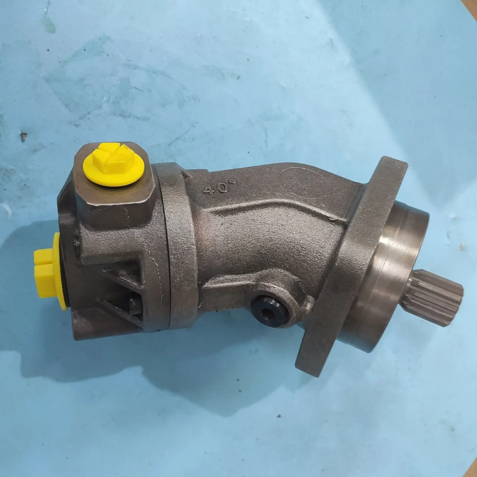
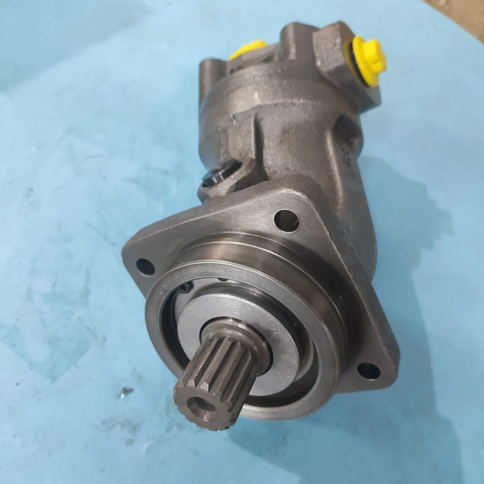
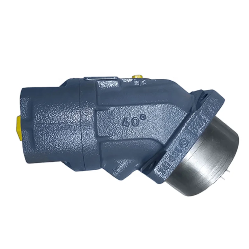
The A2F023/61R-PPB05 (Material No. R902155958) is the 23 cc-class core model within the Bosch Rexroth A2F series 61 of bent-axis fixed displacement axial piston pumps and motors. The A2F series features a bent-axis tapered piston rotary group design with fixed displacement, for use as either pump or motor in open or closed hydrostatic drive circuits.
The A2F series spans displacements from 4.93 to 1000 cm³/rev, with a nominal pressure of 400 bar (sizes 10–200) and peak pressure of 450 bar. The A2FO23/61R-PPB05 is the A2FO (open circuit pump) variant, designed for open-circuit hydraulic systems and serving as a key power component in concrete mixer trucks, construction machinery, and industrial hydraulic systems.
A2F Series Core Features: Bent-axis fixed displacement axial piston pump/motor for open and closed circuits; tapered piston design with output flow proportional to drive speed and displacement; self-centering spherical control area enabling radial load capacity of the drive shaft; optional long-life bearings (sizes 250–1000); compact lightweight design with high power density; total efficiency up to 92–96%; one-piece tapered pistons with integrated piston rings for high volumetric efficiency.
Model Code Breakdown (for procurement and engineering reference):
Using A2FO23/61R-PPB05 as example:
A2FO: Rexroth A2F series bent-axis fixed displacement axial piston pump, open-circuit version
23: Nominal size (NG), geometric displacement 22.9 cm³/rev
/61: Series 61
R: Clockwise rotation (viewed from shaft end)
PPB05: Mounting flange, port, and shaft configuration code. P = NBR seals; PB = mounting flange and port code; 05 = shaft and design variant
Application Background: The A2F/A2FM series is the industry benchmark for concrete mixer truck drum drives, construction machinery travel drives, and lifting equipment hydraulic systems, with extensive field-proven applications worldwide. The A2FO23 is widely used in concrete pump truck boom pump and mixer hydraulic systems.
Drop-in Replacement Advantage: Manufactured to exact Rexroth OEM specifications, this pump achieves complete drop-in interchangeability with the original A2F series for ISO 4-hole mounting flange, shaft dimensions, SAE main port layout, and rotation direction. Every pump undergoes 100% simulated load testing prior to shipment, validating 400 bar pressure loading, volumetric efficiency, and thermal stability under conditions replicating real-world duty cycles.
Technical Specifications
Model A2FO23/61R-PPB05:
Model Code: A2FO23/61R-PPB05
Material Number: R902155958
Series: Rexroth A2F Series 61 (Bent-Axis Fixed Displacement Pump/Motor)
Nominal Size: NG 23
Geometric Displacement: 22.9 cm³/rev
Nominal Pressure: 400 bar (continuous)
Peak Pressure: 450 bar (intermittent)
Maximum Speed (Open Circuit): 2500 rpm
Maximum Speed (Closed Circuit): 5600 rpm
Theoretical Flow at 2500 rpm: Approx. 57 L/min
Theoretical Torque (Δp = 400 bar): Approx. 126 N·m
Control Type: Fixed Displacement (Quantitative)
Rotation: Clockwise (viewed from shaft end, R code)
Mounting Flange: ISO 4-hole flange
Housing Material: High-strength cast iron
Seal Material: NBR (nitrile rubber), suitable for mineral oil-based hydraulic fluid
Operating Temperature: 30–90°C
Weight: Approx. 10.5 kg
A2F Series Displacement Size Reference:
A2F5: 4.93 cm³/rev, nominal 315 bar, peak 350 bar, max speed 5600 rpm (open) / 8000 rpm (closed), weight approx. 2.5 kg
A2F10: 10.3 cm³/rev, nominal 400 bar, peak 450 bar, max speed 3150 rpm (open) / 6000 rpm (closed)
A2F12: 12.0 cm³/rev, nominal 400 bar, peak 450 bar, max speed 3150 rpm (open) / 6000 rpm (closed)
A2F16: 16.0 cm³/rev, nominal 400 bar, peak 450 bar, max speed 3150 rpm (open) / 6000 rpm (closed)
A2F23: 22.9 cm³/rev, nominal 400 bar, peak 450 bar, max speed 2500 rpm (open) / 5600 rpm (closed)
A2F28: 28.1 cm³/rev, nominal 400 bar, peak 450 bar, max speed 2500 rpm (open) / 4750 rpm (closed)
A2F32: 32.0 cm³/rev, nominal 400 bar, peak 450 bar, max speed 2500 rpm (open) / 4750 rpm (closed)
A2F45: 45.6 cm³/rev, nominal 400 bar, peak 450 bar, max speed 2240 rpm (open) / 4250 rpm (closed)
A2F56: 56.1 cm³/rev, nominal 400 bar, peak 450 bar, max speed 2000 rpm (open) / 3750 rpm (closed)
A2F63: 63.0 cm³/rev, nominal 400 bar, peak 450 bar, max speed 2000 rpm (open) / 3750 rpm (closed)
A2F80: 80.4 cm³/rev, nominal 400 bar, peak 450 bar, max speed 1800 rpm (open) / 3350 rpm (closed)
A2F107: 106.7 cm³/rev, nominal 400 bar, peak 450 bar, max speed 1800 rpm (open) / 3350 rpm (closed)
A2F125: 125.0 cm³/rev, nominal 400 bar, peak 450 bar, max speed 1800 rpm (open) / 3350 rpm (closed)
A2F160: 160.4 cm³/rev, nominal 400 bar, peak 450 bar, max speed 1600 rpm (open) / 3000 rpm (closed)
A2F200: 200.0 cm³/rev, nominal 400 bar, peak 450 bar, max speed 1600 rpm (open) / 3000 rpm (closed)
A2F250: 250.0 cm³/rev, nominal 350 bar, peak 400 bar, max speed 1500 rpm (open) / 2500 rpm (closed)
A2F355: 355.0 cm³/rev, nominal 350 bar, peak 400 bar, max speed 1320 rpm (open) / 2240 rpm (closed)
A2F500: 500.0 cm³/rev, nominal 350 bar, peak 400 bar, max speed 1200 rpm (open) / 2000 rpm (closed)
A2F1000: 1000.0 cm³/rev, nominal 350 bar, peak 400 bar, max speed 1000 rpm (open) / 1600 rpm (closed)
Note: The above data are theoretical values without considering efficiencies and tolerances; values rounded.
Key Technical Advantages
1. Bent-Axis Design with High Volumetric Efficiency
The A2F series employs a bent-axis tapered piston rotary group design with the piston axis at a fixed 25° angle to the drive shaft axis. The piston lateral force exerted on the cylinder block is minimal, reducing the tilting moment between the cylinder block and valve plate, allowing the rotary group to maintain a stable hydrostatic bearing film at high speeds. The A2F series achieves total efficiency of 92–96% and starting torque exceeding 95%, leading its displacement class.
2. Self-Centering Spherical Control Area with Torque-Free Cylinder Support
The A2F rotary group incorporates a well-proven self-centering spherical control area design, where pistons automatically center within the spherical zone, achieving torque-free cylinder bearing support. This design reduces friction and wear between the piston and cylinder bore while enabling the drive shaft to accommodate radial loading, enhancing system design flexibility. The spherical valve plate distribution system provides automatic centering of the rotating group, ensuring consistent port timing and minimal internal leakage throughout the motor’s service life.
3. One-Piece Tapered Piston with Piston Ring Sealing
The piston features a one-piece tapered design with integrated piston rings for sealing between the piston and cylinder bore. The one-piece tapered piston with integrated piston rings delivers superior sealing performance and lower leakage compared to conventional clearance sealing. The elastic deformation capability of the piston rings compensates for thermal expansion differences between the piston and cylinder bore, maintaining stable volumetric efficiency across a wide temperature range and even after thousands of operating hours in contaminated environments.
4. Robust Rolling Bearings with Long Service Life
The drive shaft uses robust ball and roller bearing configurations selected through system-level load analysis for long service life at high speeds. The A2F series features robust construction with long service life and high power density. For sizes 250–1000, optional long-life bearings are available to further extend maintenance intervals. The pump is designed for continuous high-pressure operation in demanding environments with excellent reliability and durability.
5. Bi-Directional Rotation with Wide Hydraulic Fluid Compatibility
The A2F series supports bi-directional rotation, suitable for hydraulic systems requiring forward/reverse switching. The units are compatible with mineral oil (per DIN 51524) and HFB, HFC, and HFD environmentally acceptable hydraulic fluids. For sizes 250–1000 with HFD fluid, long-life bearings (L configuration) are required. In closed circuits, the feed pressure must be maintained between 0.2 MPa and 0.6 MPa, depending on pump speed and viscosity of hydraulic fluid.
6. High-Strength Cast-Iron Housing with Compact Lightweight Design
The housing is precision-cast from high-strength cast iron, with the material’s damping characteristics effectively suppressing structural vibration and fluid-borne noise. The A2FO23 achieves a displacement of 22.9 cm³/rev with a weight of only approximately 10.5 kg, leading its displacement class in power density. The compact structural dimensions make the A2F series particularly suitable for space-constrained mobile hydraulic applications. The mounting configuration is an ISO 4-hole flange, adaptable to diverse construction machinery and industrial equipment.
Application Areas
Concrete Mixer Trucks: Drum drive (closed circuit, one of the core application areas for the A2F series)
Concrete Pump Trucks: Boom pump hydraulic systems, pumping system auxiliary hydraulic drives
Construction Equipment: Excavator travel drives, wheel loader hydraulic drives, road roller travel hydraulic systems
Lifting Equipment: Mobile crane winch and slewing motors, crawler crane travel drives
Mining & Drilling: Mining truck hydrostatic drives, drill rig power head drive motors
Agricultural Machinery: Combine harvester hydraulic drives, high-horsepower tractor hydraulic systems
Marine & Offshore: Deck machinery hydraulic drives, marine winch hydraulic systems
Industrial Hydraulic Power Units: Hydraulic test benches, large machine tool hydraulic power sources
Expert Maintenance Tips
1. Hydraulic Fluid Cleanliness
A2F series pumps are highly sensitive to fluid contamination, particularly given the extremely tight clearances between the one-piece tapered piston and piston rings. System filtration must meet ISO 4406 18/15 or better. Regularly replace hydraulic fluid (every 1,000–3,000 operating hours or every six months) to improve pump service life and efficiency. Replace filter elements at 500 hours after first commissioning, then every 1,000 operating hours or 6 months, whichever comes first.
2. Pre-Start Priming and Air Bleeding
Before first start, fill the pump housing with clean hydraulic fluid through the case drain port — the pump must not be started without priming. After installation, turn the drive shaft by hand several revolutions to confirm free rotation without binding. Start at low speed with zero load and run for 5–10 minutes. Verify continuous bubble-free flow from the case drain. For “drive shaft upwards” installation positions, filling and air bleeding must be performed completely to avoid dry-running risk.
3. Closed Circuit Charge Pressure Control
When the A2F is used in closed-loop circuits, an auxiliary charge pump is required to maintain minimum suction pressure, preventing cavitation and ensuring the piston slippers remain in contact with the valve plate. Closed circuit charge pressure should be maintained between 0.2 MPa and 0.6 MPa. The charge pump displacement must satisfy system leakage compensation and cooling flow requirements. Minimum absolute pressure at the suction port must be maintained at 0.08 MPa (absolute) or higher.
4. Hydraulic Fluid Viscosity and Temperature Control
Optimum operating viscosity range is 17–180 cSt. Case drain temperature is influenced by pressure and speed and is always higher than reservoir temperature. System temperature must never exceed 115°C at any point. The operating temperature range is 30–90°C; for continuous high-temperature applications, select a higher viscosity grade hydraulic fluid.
5. Installation Alignment and Plumbing
Ensure drive shaft alignment with radial deviation not exceeding 0.05 mm. The case drain line must return directly to the reservoir with back pressure not exceeding 2 bar (0.2 MPa). The drain outlet must terminate below oil level at all times. Inlet velocity must not exceed 1.5 m/s to prevent cavitation. For tapered shaft models, torque must be transmitted via the tapered press fit.
6. Tapered Shaft Installation Requirements
The A2FO23/61R-PPB05 features a tapered shaft with threaded pin and Woodruff key (DIN 6888), where torque must be transmitted via the tapered press fit. During installation, ensure the tapered surface is clean and free of oil contamination, and use dedicated tools to tighten the threaded pin to specified torque. During disassembly, use dedicated pulling tools and never strike the shaft end face to avoid damaging the tapered surface and bearings.