
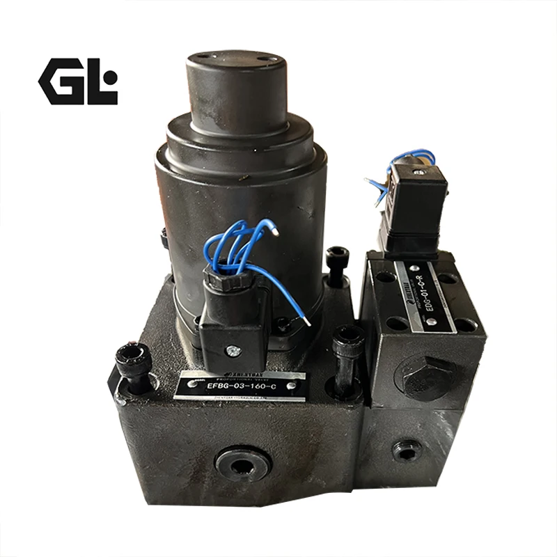


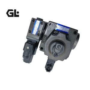


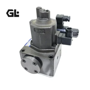

EFBG-03-160-C Yuken Proportional Valve 160 L/min 24.5 MPa
| Model Number | EFBG-03-160-C |
|---|
Product Description
Product Overview
The EFBG-03-160-C series electro-hydraulic proportional relief and flow control valve (including model EFBG-03-160-H-21T233-L and the pilot valve EDG-01V-H-PNT13-61T) is manufactured to original YUKEN technical standards. Belonging to the EFBG series with size 03 (NG10 / CETOP 3 / ISO 4401-03), this valve is a high-performance electro-hydraulic proportional pressure and flow compound control valve. It features a subplate mounting design that integrates proportional relief valve and proportional flow valve functions into a single unit. Two independent electrical signals separately control system pressure and flow, enabling continuous, precise proportional regulation of actuator speed and pressure.
The EFBG-03-160-C features pressure adjustment range C (1.4 to 14 MPa) with a maximum adjustable flow of 160 L/min and maximum operating pressure of 24.5 MPa (3550 psi). The EDG-01V-H-PNT13-61T is a matching proportional pilot relief valve that employs a compact DC solenoid and direct-acting relief valve design. It serves as a pilot valve for low flow rate hydraulic systems, controlling pressure in proportion to the input current. The valve features an energy-saving design that automatically adjusts pump pressure according to load pressure, maintaining the pressure differential at a minimum of only 0.6 to 0.9 MPa, thereby reducing system energy consumption and fluid temperature rise.
This product is dimensionally and functionally identical to the original YUKEN EFBG-03-160 series valve, offering true drop-in interchangeability for direct replacement of same-specification OEM valves. Every unit undergoes 100% bench testing under simulated working conditions, including rated pressure holding, flow-signal linearity, pressure regulation characteristics, and internal leakage verification.
Technical Specifications (Bulleted List)
General Specifications
Model: EFBG-03-160-C / EFBG-03-160-H-21T233-L
Matching Pilot Valve: EDG-01V-H-PNT13-61T
Product Series: EFBG-03 (Size 10 / NG10 / CETOP 3 / ISO 4401-03)
Design: Electro-hydraulic proportional relief and flow control valve (pressure-flow compound control valve)
Connection: Subplate mounting
Installation Position: Any
Hydraulic Parameters
Maximum Operating Pressure: 24.5 MPa (250 kgf/cm² / 3550 psi)
Maximum Adjustable Flow: 160 L/min
Flow Adjustment Range: 1 to 160 L/min
Valve Pressure Differential: 0.6 MPa (6 kgf/cm²)
Required Pilot Flow: 1 L/min steady state; 3 L/min transient
Hydraulic Fluid: Mineral-based hydraulic oil
Applicable Temperature: 20 to 60°C
Pressure Control Parameters (C Type)
Pressure Adjustment Range: C type 1.4 to 14 MPa
Rated Current: C type 890 mA
Coil Resistance: 10 Ω
Hysteresis: Less than 3%
Repeatability: 1%
Flow Control Parameters
Rated Current: 800 mA
Coil Resistance: 10 Ω
Hysteresis: Less than 7%
Repeatability: 1%
Matching Pilot Valve EDG-01V-H-PNT13-61T Parameters
Type: Proportional solenoid pilot relief valve
Maximum Operating Pressure: 24.5 MPa (3550 psi)
Minimum Flow Rate: 0.3 L/min
Pressure Adjustment Range: H type 1.4 to 24.5 MPa
Control: Proportional solenoid actuated, pressure proportional to input current
Materials & Construction
Valve Body: High-strength cast steel
Control Spool: Carburized steel, precision ground
Seals: NBR (standard)
Surface Treatment: Phosphating / anti-corrosion coating
Key Technical Advantages
1. Pressure-Flow Compound Control with Energy-Saving Design
The EFBG-03-160-C integrates proportional relief valve and proportional flow valve functions into a single unit, with two independent electrical signals separately controlling pressure and flow. The valve features an energy-saving design that automatically adjusts pump pressure according to load pressure, maintaining a pressure differential of only 0.6 to 0.9 MPa between pump and load, thereby minimizing system energy consumption and fluid temperature rise. The valve also features temperature compensation for stable flow control regardless of oil temperature variations.
2. High-Accuracy Closed-Loop Control with Fast Response
The valve employs a closed-loop control system with a compact proportional solenoid and linear position detector (LVD), achieving high-response, high-accuracy flow and pressure control. Pressure control hysteresis is less than 3%, flow control hysteresis is less than 7%, and repeatability is 1% for both. This enables precise control of actuator speed and output pressure, meeting the demanding requirements of injection molding machines for mold closing, injection, and holding processes.
3. Precision Spool Machining with Low Pressure Loss
The control spool is precision-ground from carburized steel with micron-level clearance control. All valve ports are CFD-optimized, significantly reducing pressure loss and enhancing system energy-saving benefits. The low valve pressure differential of 0.6 MPa further reduces system energy losses.
4. Strong Contamination Tolerance and Reliable Operation
The EFBG series valve features a rational structural design and strong anti-contamination performance, providing tolerance to particulate contamination for reliable operation in industrial field environments. The spool metering notches are optimized to maintain high-accuracy flow control while reducing the risk of spool binding caused by particulate contaminants.
5. 100% Simulated Working Condition Testing and Drop-in Interchangeability
Every EFBG-03-160-C valve undergoes 100% bench testing prior to shipment, covering 24.5 MPa rated pressure holding, flow-signal linearity verification, pressure regulation characteristic calibration, and internal leakage measurement. Mounting dimensions, port positions, and performance curves are strictly matched to the original YUKEN valve, enabling direct drop-in replacement without modifying piping or control programs.
Application Areas
Injection Molding Machines: Precise pressure and speed control for mold closing, injection, and holding processes; particularly suitable for energy-saving retrofits of injection molding machine hydraulic systems
Hydraulic Presses: Proportional regulation of pressing speed and pressure
Die Casting Machines: Precise control of shot speed and intensification pressure
Hydraulic Power Units: Core regulating element in main control systems for precise control of actuator motion characteristics
Automated Production Lines: Excellent performance in hydraulic transmission applications requiring frequent start-stop or speed changes
Metallurgical Equipment: Precision control for continuous casting machines and rolling mill auxiliary hydraulic systems
Construction Machinery: Pressure-flow compound control for small-to-medium hydraulic systems
Expert Maintenance Tips
Installation Guidelines
The EFBG-03-160-C series can be mounted in any position. Mounting surface flatness must be ≤ 0.05 mm. Tighten mounting bolts diagonally in stages to the specified torque value. The mounting surface conforms to ISO 4401-03 for matching with CETOP 3 standard subplates.
Thoroughly flush all piping circuits before installation. Ensure no welding slag, metal chips, or particulate contaminants remain. Prior to first operation, circulate the system through a 10 μm filter element for a minimum of 30 minutes.
Air Bleeding: After installation, air must be bled from the pressure and flow solenoids. The installation posture must allow the air bleed valve to be rotated to the upward position. Set at approximately 1.5 MPa (15 kgf/cm²) during trial operation and bleed thoroughly to obtain stable pressure control.
Electrical connections must use the matching power amplifier to ensure control signal compatibility. Control signal cables should be shielded, with the shield grounded at one end.
Routine Maintenance Procedures
Fluid Cleanliness Management: Maintain system fluid cleanliness at ISO 4406 19/17/14 or better. Check fluid particulate contamination every 500 operating hours and replace filter elements and hydraulic fluid when contamination exceeds limits.
Coil Resistance Verification: Measure solenoid coil resistance (standard value 10 Ω) every 1,000 operating hours. Replace the coil if deviation exceeds ± 10%.
Pressure Setting Verification: Periodically verify pressure adjustment range settings. The C-type valve pressure setting must not exceed 14 MPa. If pressure control becomes unstable, first check whether air bleeding is adequate and whether the pilot valve filter is clogged.
Safety Valve Setting: To prevent the preset pressure from becoming unstable, the safety valve setting should be 2 MPa (20.4 kgf/cm²) above the upper limit of the pressure adjustment range at the flow rate.
Seal Replacement: Under normal operating conditions, replace valve seals every 3,000-5,000 operating hours. For high-temperature applications, reduce the interval to 2,000 hours.


Company Profile

Frequently Asked Questions
1.What ls our Main Products?
1.Hydraulic pump
2.Hydraulic valve
3.Hydraulic motor
4.Hydraulic cylinder
5.Hydraulic parts
2. What about the MOQ?
3.What are your advantages?
- Adhere to quality first.
- Support customization, ODM & OEM service.
- 1-year warranty and complete after-sales support.
- Safe and fast shipping worldwide.
- 24-hour online service for your inquiries.
4.Are you a manufacturer? What’s your delivery time?
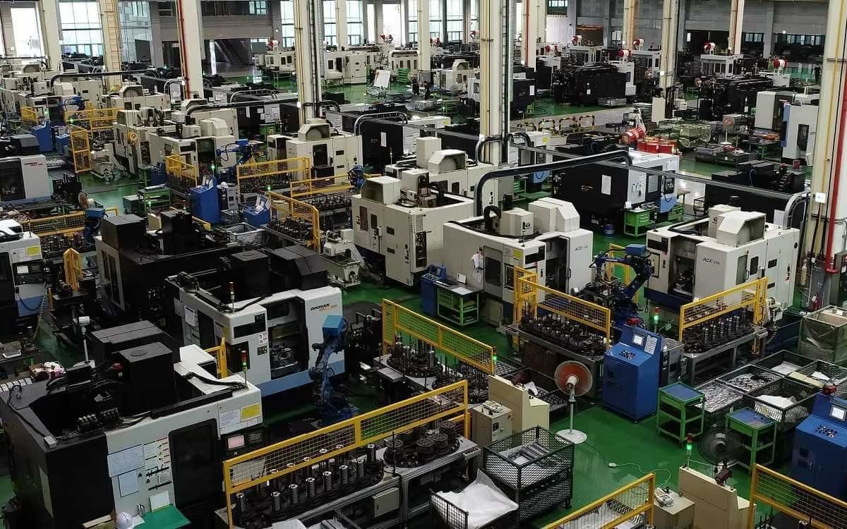
Yes, we are a manufacturer with our own factory.
Common models are in stock, and orders are usually shipped within 1–3 days.
5.Which payment methods are accepted?
We accept T/T, L/C, PayPal, VISA, Western Union, Apple Pay, Google Pay, Afterpay (Clearpay), Klarna, and Trade Assurance.
For full orders: 30% deposit, balance before shipment.
For small/sample orders: full payment in advance.
6.How will you deliver my goods?
We offer flexible shipping options: DHL, UPS, FedEx, TNT, EMS, as well as air or sea freight.
All deliveries ensure door-to-door fast and safe service.
7.How do you inspect and guarantee your products?
All products are tested before shipment to ensure perfect working condition.
We offer a 12-month warranty — if a product fails due to quality issues, we provide free spare parts or repair support.
8.What about after-sales service?
If you encounter any problem during use, please contact your sales manager or our support team at any time.
We will respond quickly and help solve the issue efficiently.
9.What are your main applications?
- Hydraulic systems
- Agricultural machinery
- Construction machinery
- Automobile industry
- Local distributors and maintenance centers
10.Can I get a discount for bulk orders?
Yes. We offer competitive wholesale prices and try our best to give benefits to long-term partners.
Shoot Us An Email
Professional Manufacturer