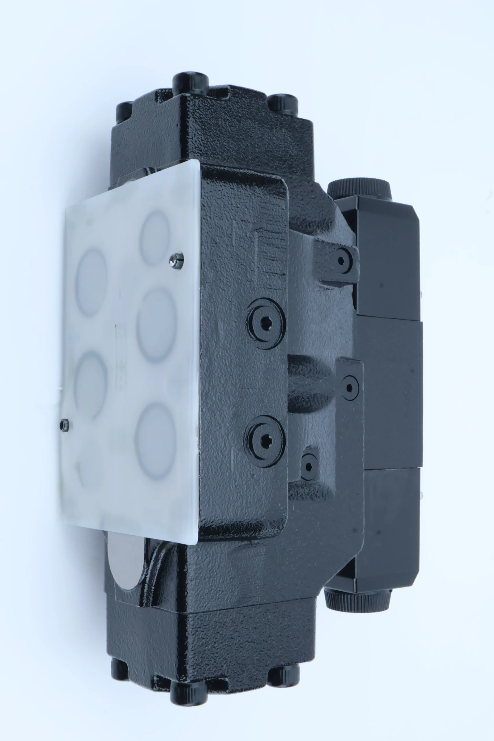
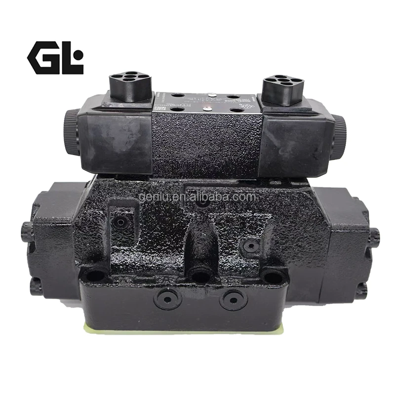

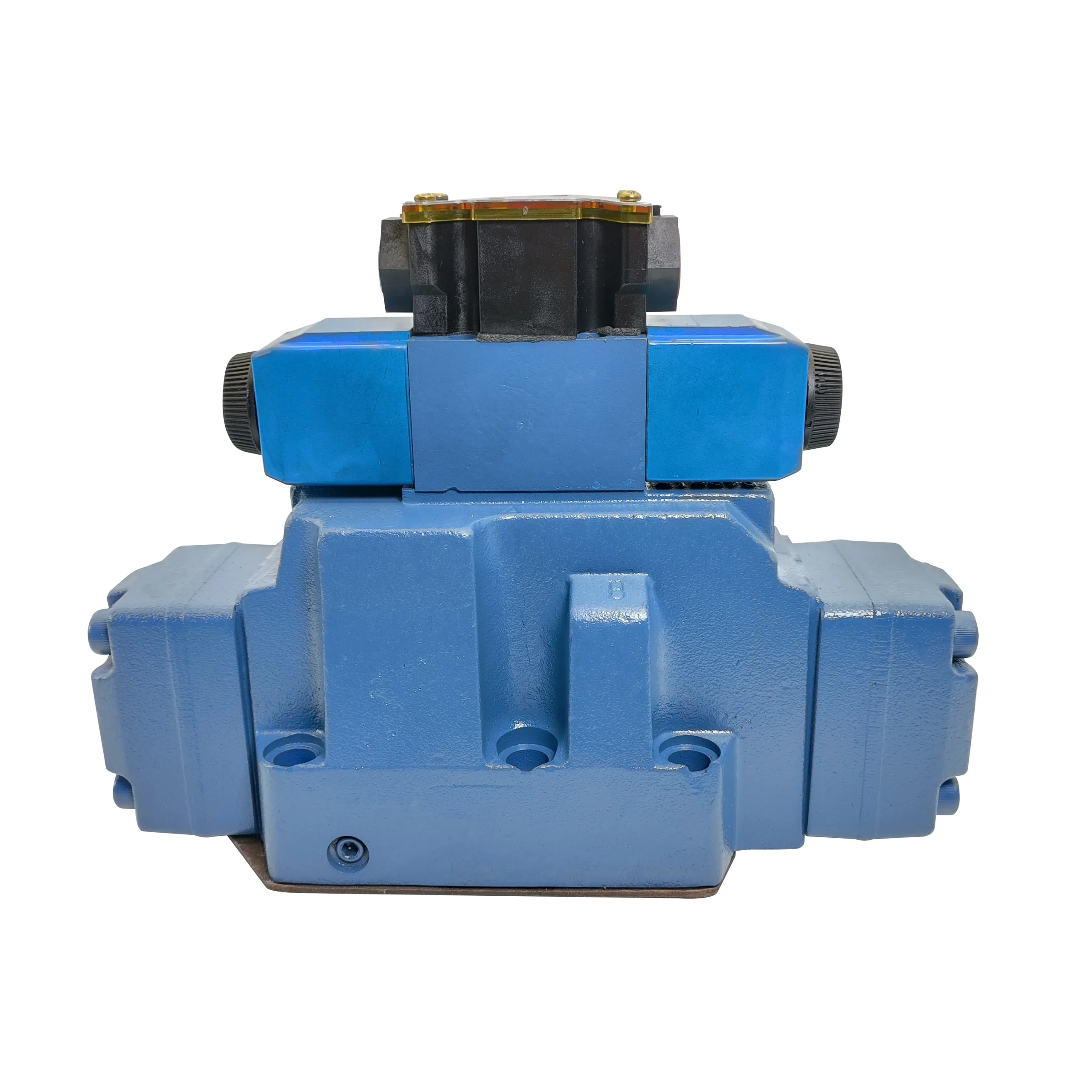

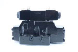


DG5V-8-H-2C-M-U-H-10 Hydraulic Electro-hydraulic Directional Valve DG5V DG4V DG5S KBDG5V KBFDG5V Hydraulic Solenoid Valve
I. Technical Parameters
1.
Flow parameter
Rated flow: 60 L/min (at 1500 rpm and a working pressure of 16MPa), suitable for the reversing regulation requirements of medium and high-pressure medium flow hydraulic systems
2.
Maximum flow rate: 80 L/min (at working pressure of 10MPa), reversing flow control accuracy ±2% (at rated flow), flow repeatability accuracy ±1%
3.
Work pressure
Continuous working pressure: 21 MPa (210 bar), capable of stably carrying medium and high-pressure cyclic reversing operations for a long time, suitable for scenarios with load fluctuations
4.
Instantaneous peak pressure: 25 MPa (250 bar), single duration ≤10 seconds, suitable for extreme working conditions such as reversing start and stop, load impact, etc
5.
Control mode:
Control type: Electro-hydraulic proportional commutation control, input signal 4-20mA DC current signal, signal resolution 0.01mA, supports bidirectional proportional regulation
6.
Response characteristics: Step response time ≤40ms (from 10% to 90% of the rated flow), commutation switching time ≤30ms, no commutation shock or shock amount ≤5%
7.
Structural form: Slide valve type structure, single-stage proportional control (model “DG5V” indicates series and structural grade); The valve core is made of high-strength alloy steel (surface nitrided treatment, hardness HV900-1100), and the valve sleeve is a tin bronze-based alloy. The “H-2C” marking features a “H” type function and dual electromagnet control, while “M-U-H-10” indicates SAE installation, fluororubber sealing, and interface specifications
8.
Oil requirements
Applicable oil type: L-HM 46 or 68 anti-wear hydraulic oil is recommended. For low-temperature working conditions (below -20℃), L-HV 68 low-temperature anti-wear hydraulic oil should be selected, with a viscosity range of 18-300 mm²/s
9.
Working oil temperature: -20℃ to 80℃. The oil cleanliness should reach ISO 16/13 grade (NAS 7 grade). A 5μm high-pressure filter is installed at the oil inlet, and a 10μm fine filter is added at the oil return port
10.
Installation and adaptation
Installation type: SAE C3 flange installation, connection hole specification M14×1.5, positioning pin diameter Φ8mm, valve body sealing adopts O-ring (material is fluororubber)
11.
Oil port specifications: Oil inlet P (G2), return oil port T (G2.5), working oil port A/B (G2), supports bidirectional reversing, overall weight approximately 15 kg, can be installed horizontally or vertically in both directions (for vertical installation, make sure the electrical connector is facing down)
twelve
Other parameters: Pressure loss ≤0.6MPa (at rated flow), internal leakage ≤0.2 L/min (at 21MPa), working life ≥1 million reversing cycles, electrical connector protection grade IP65, rated power of proportional electromagnet 12W, ambient temperature -30℃ to 85℃Ii. Working Principle
This valve is an electro-hydraulic proportional directional control valve. Its core consists of a proportional electromagnet (with two ends), a valve core, a valve sleeve, a reset spring, a pressure compensation valve and an electrical connector. The axial displacement of the valve core is controlled by an electrical signal to achieve the reversing of the oil circuit and the proportional regulation of the flow rate. The “H” type neutral position can control the specific state of the oil circuit. The specific process is as follows:
1.
Electrical signal input and force conversion: The control system outputs a 4-20mA DC proportional signal, which is transmitted to the corresponding proportional electromagnet through the electrical connector. The electromagnet generates proportional electromagnetic force based on the signal strength, overcoming the elastic force of the reset spring to push the valve core to make axial displacement along the valve sleeve axis. The signal strength and the displacement of the valve core have A linear proportional relationship. The double-ended electromagnets respectively control the valve core to reverse towards the A/B ends
2.
Reversing and flow regulation: The displacement of the valve core changes the connection state of the P, A, B, and T oil ports on the valve sleeve: When the electromagnet at end A is energized, the valve core moves towards end A, and port P connects with port A and Port B connects with port T. High-pressure oil enters the roeless cavity of the actuator to drive its action. When the electromagnet at end B is energized, the valve core moves towards end B. Port P connects with port B and Port A connects with port T, and the actuator acts in the opposite direction. The displacement of the valve core determines the opening degree of the oil port, achieving proportional flow regulation (continuously adjustable from 5 to 80 L/min).
3.
Neutral function control: When both ends of the electromagnets are de-energized (signal ≤3mA), the reset spring pushes the valve core back to the neutral position. The “H” type neutral function connects the P, A, B, and T ports, allowing direct oil intake and return. The actuator is in a floating state (can move freely), and at the same time, the system pressure is relieved, making it suitable for operation scenarios where the actuator needs to “follow”
4.
Pressure compensation and stability control: The integrated pressure compensation valve detects the pressure difference between port P and port A/B in real time. When the load changes and causes pressure fluctuations at the working oil port, the compensation valve automatically adjusts the opening degree of the damping hole in the valve core to maintain a constant pressure difference at both ends of the oil port. Even if the system pressure varies within the range of 5 to 21MPa, the flow control accuracy can still be maintained within ±2%, ensuring the stable movement speed of the actuator
1.
Flow parameter
Rated flow: 60 L/min (at 1500 rpm and a working pressure of 16MPa), suitable for the reversing regulation requirements of medium and high-pressure medium flow hydraulic systems
2.
Maximum flow rate: 80 L/min (at working pressure of 10MPa), reversing flow control accuracy ±2% (at rated flow), flow repeatability accuracy ±1%
3.
Work pressure
Continuous working pressure: 21 MPa (210 bar), capable of stably carrying medium and high-pressure cyclic reversing operations for a long time, suitable for scenarios with load fluctuations
4.
Instantaneous peak pressure: 25 MPa (250 bar), single duration ≤10 seconds, suitable for extreme working conditions such as reversing start and stop, load impact, etc
5.
Control mode:
Control type: Electro-hydraulic proportional commutation control, input signal 4-20mA DC current signal, signal resolution 0.01mA, supports bidirectional proportional regulation
6.
Response characteristics: Step response time ≤40ms (from 10% to 90% of the rated flow), commutation switching time ≤30ms, no commutation shock or shock amount ≤5%
7.
Structural form: Slide valve type structure, single-stage proportional control (model “DG5V” indicates series and structural grade); The valve core is made of high-strength alloy steel (surface nitrided treatment, hardness HV900-1100), and the valve sleeve is a tin bronze-based alloy. The “H-2C” marking features a “H” type function and dual electromagnet control, while “M-U-H-10” indicates SAE installation, fluororubber sealing, and interface specifications
8.
Oil requirements
Applicable oil type: L-HM 46 or 68 anti-wear hydraulic oil is recommended. For low-temperature working conditions (below -20℃), L-HV 68 low-temperature anti-wear hydraulic oil should be selected, with a viscosity range of 18-300 mm²/s
9.
Working oil temperature: -20℃ to 80℃. The oil cleanliness should reach ISO 16/13 grade (NAS 7 grade). A 5μm high-pressure filter is installed at the oil inlet, and a 10μm fine filter is added at the oil return port
10.
Installation and adaptation
Installation type: SAE C3 flange installation, connection hole specification M14×1.5, positioning pin diameter Φ8mm, valve body sealing adopts O-ring (material is fluororubber)
11.
Oil port specifications: Oil inlet P (G2), return oil port T (G2.5), working oil port A/B (G2), supports bidirectional reversing, overall weight approximately 15 kg, can be installed horizontally or vertically in both directions (for vertical installation, make sure the electrical connector is facing down)
twelve
Other parameters: Pressure loss ≤0.6MPa (at rated flow), internal leakage ≤0.2 L/min (at 21MPa), working life ≥1 million reversing cycles, electrical connector protection grade IP65, rated power of proportional electromagnet 12W, ambient temperature -30℃ to 85℃Ii. Working Principle
This valve is an electro-hydraulic proportional directional control valve. Its core consists of a proportional electromagnet (with two ends), a valve core, a valve sleeve, a reset spring, a pressure compensation valve and an electrical connector. The axial displacement of the valve core is controlled by an electrical signal to achieve the reversing of the oil circuit and the proportional regulation of the flow rate. The “H” type neutral position can control the specific state of the oil circuit. The specific process is as follows:
1.
Electrical signal input and force conversion: The control system outputs a 4-20mA DC proportional signal, which is transmitted to the corresponding proportional electromagnet through the electrical connector. The electromagnet generates proportional electromagnetic force based on the signal strength, overcoming the elastic force of the reset spring to push the valve core to make axial displacement along the valve sleeve axis. The signal strength and the displacement of the valve core have A linear proportional relationship. The double-ended electromagnets respectively control the valve core to reverse towards the A/B ends
2.
Reversing and flow regulation: The displacement of the valve core changes the connection state of the P, A, B, and T oil ports on the valve sleeve: When the electromagnet at end A is energized, the valve core moves towards end A, and port P connects with port A and Port B connects with port T. High-pressure oil enters the roeless cavity of the actuator to drive its action. When the electromagnet at end B is energized, the valve core moves towards end B. Port P connects with port B and Port A connects with port T, and the actuator acts in the opposite direction. The displacement of the valve core determines the opening degree of the oil port, achieving proportional flow regulation (continuously adjustable from 5 to 80 L/min).
3.
Neutral function control: When both ends of the electromagnets are de-energized (signal ≤3mA), the reset spring pushes the valve core back to the neutral position. The “H” type neutral function connects the P, A, B, and T ports, allowing direct oil intake and return. The actuator is in a floating state (can move freely), and at the same time, the system pressure is relieved, making it suitable for operation scenarios where the actuator needs to “follow”
4.
Pressure compensation and stability control: The integrated pressure compensation valve detects the pressure difference between port P and port A/B in real time. When the load changes and causes pressure fluctuations at the working oil port, the compensation valve automatically adjusts the opening degree of the damping hole in the valve core to maintain a constant pressure difference at both ends of the oil port. Even if the system pressure varies within the range of 5 to 21MPa, the flow control accuracy can still be maintained within ±2%, ensuring the stable movement speed of the actuator
Iii. Product Features and Advantages
1.
High proportional reversing accuracy: The 4-20mA signal has a strict linear relationship with the displacement of the valve core and the flow rate. The flow control accuracy is ±2%, the repeat accuracy is ±1%, and the reversing repeat positioning accuracy is ±0.01mm. It can achieve the coordinated stepless regulation of the movement direction and speed of the actuator, replacing the traditional “reversing valve + throttle valve” combination scheme and reducing the system complexity by 60%
2.
The median function has excellent adaptability: The “H” type median function enables P, A, B, and T to be connected at the median, which not only allows the actuator to float (such as the lower movement of the crane boom), but also completes the system unloading without the need for additional unloading valves. It is suitable for scenarios that require a combination of “movement + unloading”, and saves 30% energy compared to the “O” type function
3.
Strong anti-pollution and reliability
The valve core is made of nitrided alloy steel, and the valve sleeve is a tin bronze-based alloy. The fit clearance is controlled within 0.005-0.01mm. Under ISO 16/13 grade polluted environments (such as construction machinery dust and industrial oil stains), the working life can reach 1 million reversing cycles, which is 40% longer than that of ordinary electro-hydraulic valves
4.
The electrical connector with IP65 protection grade can adapt to outdoor rain and dust environments. The double-ended electromagnet adopts a sealed structure, which is moisture-proof and oil-proof, reducing the failure and shutdown rate by 50%
5.
Compact structure and good integration: Proportional reversing, pressure compensation, and median unloading are integrated into one unit. The overall volume is reduced by 40% compared to the split solution, and there is no need to install additional compensation valves and unloading valves. The standardized SAE C3 flange installation can directly replace the ordinary directional control valve of the same specification, reducing the modification cost by 60%
6.
Strong wide working condition adaptability: It can reverse normally without preheating in a low-temperature environment of -20℃, and the response speed does not decline in a high-temperature working condition of 80℃. Supports horizontal/vertical installation, suitable for different layouts such as construction machinery chassis and industrial equipment hydraulic stations, and compatible with various hydraulic oils including mineral oil and synthetic ester
Iv. Usage Functions and Purposes
1. Usage function
•
As a core component for reversing and flow control in medium and high-pressure hydraulic systems, it can achieve stepless flow regulation ranging from 5 to 80 L/min and bidirectional reversing of the oil circuit, driving hydraulic cylinders and motors to precisely coordinate the control of movement direction and speed (such as the adjustment of the flipping direction and speed of excavator buckets and the control of the opening and closing direction and speed of injection molding machines).
•
Median function control: The “H” type median enables the floating of the actuator and the unloading of the system, which is suitable for follow-up operation scenarios such as “crane boom lowering and forklift fork lowering”, and at the same time avoids energy waste caused by the system’s no-load high-voltage operation
•
Pressure compensation and stabilization function: Automatically maintain a stable flow rate when the load changes, suitable for scenarios of “alternating actions of multiple actuating elements” (such as the alternating actions of lifting and steering of a loader), ensuring that the speeds of each action do not interfere with each other and enhancing the coordination of operations
•
Safety protection function: When the electromagnet loses power, it automatically returns to the neutral position to unload, preventing unexpected actions of the actuator. When the pressure exceeds 25MPa, the built-in unloading structure opens to protect the valve body and pipeline from impact damage
2. Uses
•
Construction machinery: boom/bucket reversing and speed control for 10-20-ton crawler excavators, lifting/reversing adjustment for 15-ton wheel loaders, lifting/tilting reversing control for 5-8-ton hydraulic forklifts
•
Industrial equipment: Mold opening and closing/ejection reversing and speed regulation for 500-1200-ton injection molding machines, pressing/return reversing control for large hydraulic presses, telescopic/rotating reversing and precise speed control for hydraulic mechanical arms in automated production lines
•
Special machinery: Steering, reversing and speed regulation of ship hydraulic steering gears, boom lifting/luffing reversing control of large cranes, and walking reversing and speed regulation of small underground loaders in mines
V. Applicable Machines and Scenarios
1. Applicable machines
•
Construction machinery: 10-20 ton crawler excavators, 15 ton wheel loaders, 5-8 ton hydraulic forklifts
•
Industrial equipment: 500-1200 ton injection molding machines, large hydraulic presses, and hydraulic robotic arms for automated production lines
•
Special machinery: Marine hydraulic steering gears, large cranes, small underground mine loaders
2. Applicable scenarios
•
Precise reversing speed regulation scenarios: Precise reversing of injection molding machine opening and closing molds (reversing impact ≤5%), assembly operations of hydraulic mechanical arms (positioning accuracy ≤0.5mm), and improvement of operation quality by relying on ±2% flow accuracy and ±0.01mm reversing positioning accuracy
•
Median follow-up unloading scenarios: The crane boom is lowered for follow-up operation, the forklift forks are lowered without power, and the hydraulic platform descends smoothly. The “H” type median can achieve the floating of the actuator and system energy conservation
•
Harsh environmental scenarios: underground rock powder environment in mines, outdoor infrastructure dust environment, high salt spray environment in ports. Strong anti-pollution performance and IP65 protection can extend the maintenance cycle to over 2,000 hours
•
Integrated modification scenarios: Upgrading the reversing speed control system of old equipment (such as changing the ordinary reversing valve + throttle valve to a proportional reversing valve), compact hydraulic system design of new equipment, and the integrated structure reduces installation space and modification costs
Six. Similar models
1. Models of the same series
•
DG5V-6-H-2C-M-U-H-10: Electro-hydraulic proportional directional control valve, rated flow 40 L/min (1500 rpm), continuous pressure 21MPa, suitable for medium and small flow scenarios such as 8-10 ton excavators and injection molding machines under 500 tons. The installation dimensions are the same as those of model 8
•
DG5V-10-H-2C-M-U-H-10: Electro-hydraulic proportional directional control valve, rated flow 80 L/min (1500 rpm), continuous pressure 21MPa, suitable for high-flow scenarios such as 20-25 ton excavators and 1200-1500 ton injection molding machines
•
DG5V-8-O-2C-M-U-H-10: The parameters are consistent with those of the 8-H model. The “O” marking indicates a neutral “O” type function (four-port closed), making it suitable for scenarios where the actuator needs to maintain voltage
2. Similar alternative models
•
4WEH10E: Electro-hydraulic proportional directional control valve, rated flow 60 L/min, continuous pressure 21MPa, adopts direct-acting proportional control, response time ≤35ms, suitable for scenarios with high requirements for response speed
•
DBETE-6X/100G24: Proportional Pressure Flow reversing compound valve, rated flow 60 L/min, continuous pressure 21MPa, integrates pressure, flow and reversing control, suitable for systems that require multi-parameter coordinated regulation
•
EPC-60: Electromagnetic proportional directional control valve, rated flow rate 60 L/min, continuous pressure 21MPa, more compact structure (weight approximately 12 kg), suitable for scenarios with limited installation space
Vii. Precautions for Use
1.
Core norms for Oil and Fluid Management
Strictly use L-HM 46/68 or L-HV 68 anti-wear hydraulic oil. Do not mix different brands, grades of oil or oil containing impurities to avoid valve core jamming and proportional electromagnet wear. Before changing the oil, the valve chamber and the inlet and return oil pipelines should be thoroughly flushed with new oil (the flushing oil volume should be no less than 1.5 times the system volume)
2.
The cleanliness of the 5μm filter at the oil inlet should be checked every 300 hours, and the 10μm filter at the oil return port should be replaced every 600 hours. Hydraulic oil should be replaced every 1500 to 2000 hours. When changing the oil, the sediment at the bottom of the oil tank should be cleaned (a sediment thickness of ≤1mm is normal), and the moisture content of the oil should be ≤0.15%
3.
Installation accuracy control
Flange face sealing installation is adopted. The flatness error of the flange contact surface is ≤0.02mm. The installation bolts are evenly tightened (torque 200-250 N·m) to avoid valve body deformation causing valve core jamming. The electrical connector should be installed facing down to prevent rainwater and oil stains from seeping in
4.
The diameter of the inlet and return oil pipelines shall not be less than Φ40mm, the number of pipeline elbows shall not exceed 2, and throttling elements shall not be installed within a range of 1m from the valve body to reduce pressure loss. When installed vertically, the valve body should be pre-filled with hydraulic oil to prevent cavitation during startup
5.
Debugging and operation monitoring
Before the initial commissioning, the valve cavity should be flushed with low-pressure oil (5MPa) to expel air. Connect the 4-20mA signal source, adjust the signals of the electromagnets at ends A and B respectively, test the commutation flexibility and flow linearity, and ensure that the linearity error is ≤2%. For low-temperature start-up (below -15℃), the oil should be preheated to above 10℃ first
6.
Core parameters for monitoring during operation: Oil temperature 30-75℃ (if the temperature exceeds 80℃, the machine needs to be shut down to check the cooling system), working pressure ≤21MPa, reversing impact ≤5%. If “reversing jamming”, “normal signal but no reversing” or leakage exceeds 0.3L /min, the machine should be stopped immediately to check for valve core jamming, filter blockage or proportional electromagnet failure
7.
Maintenance and upkeep nodes
Check the contact condition of the electrical connector every 800 hours. If it is loose or oxidized, it needs to be ground. Disassemble and inspect the wear of the valve core and valve sleeve every 1500 hours. When the fit clearance exceeds 0.015mm, the valve core assembly needs to be replaced
8.
The linearity of the proportional control is calibrated every 2000 hours. The stroke of the double-ended electromagnet is adjusted through a dedicated test bench to ensure that the signal matches the flow linearly. The reversing positioning error is controlled within ±0.01mm
9.
Security and storage requirements
Before maintenance or repair, the hydraulic power source and control power supply must be cut off. Open the pressure relief valve to reduce the pressure to 0MPa. Disassembly can only be carried out when the oil temperature drops below 40℃. When disassembling, make sure to mark the installation direction of the valve core to avoid reverse reinstallation causing malfunctions
10.
When the machine is out of service for a long time (more than 3 months), the oil in the valve should be drained and anti-rust oil injected. The oil port and the interface of the electrical connector should be sealed. It should be stored in a dry and well-ventilated environment (humidity ≤65%), avoiding direct sunlight or proximity to high-temperature heat sources