

Product Overview:
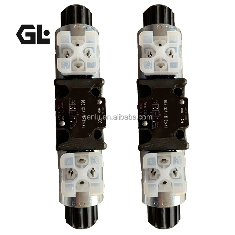
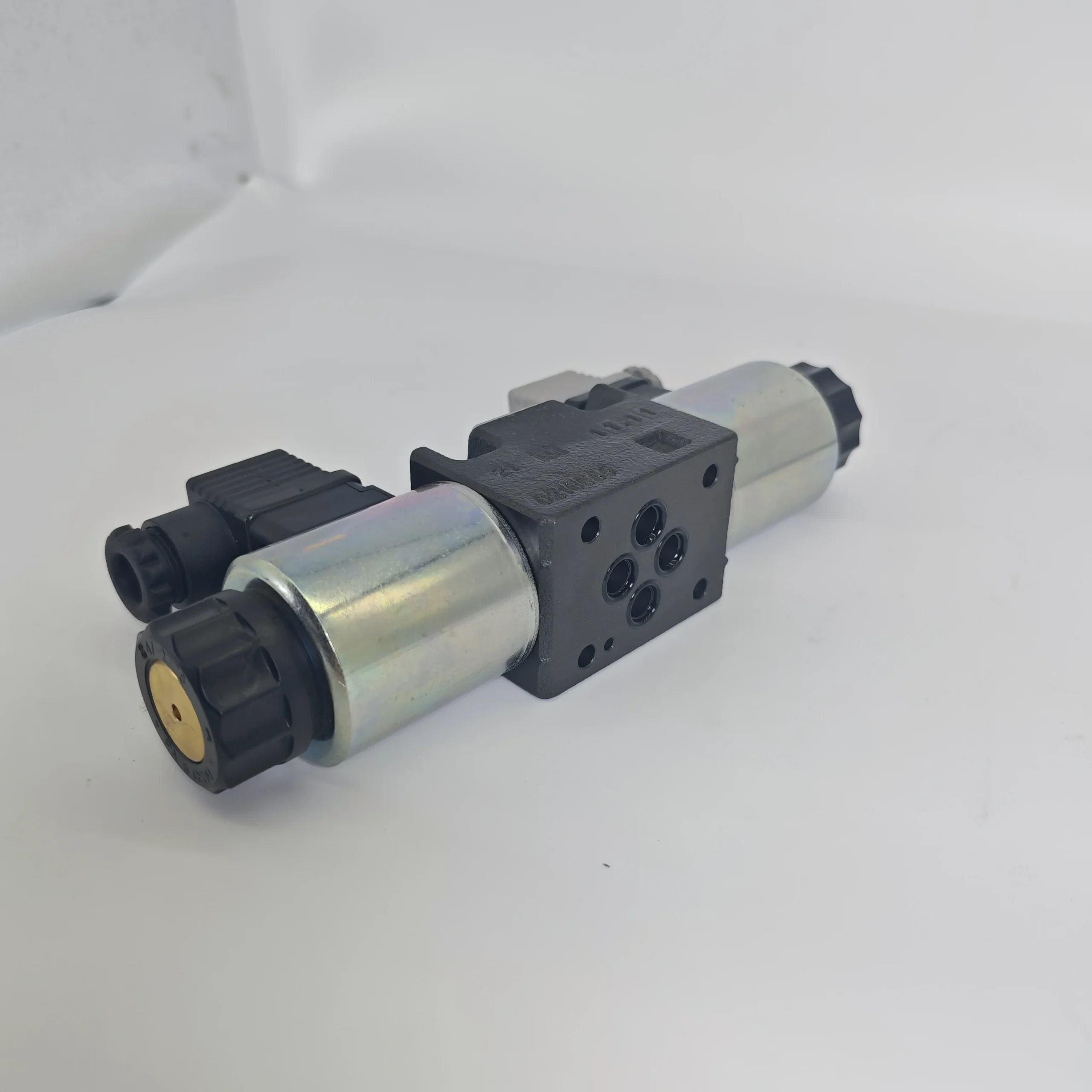
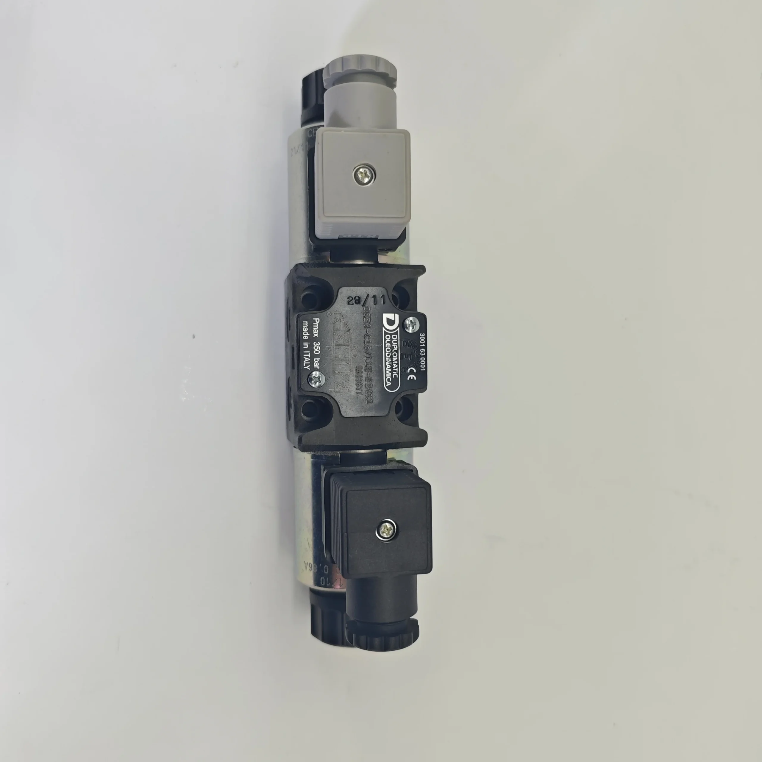
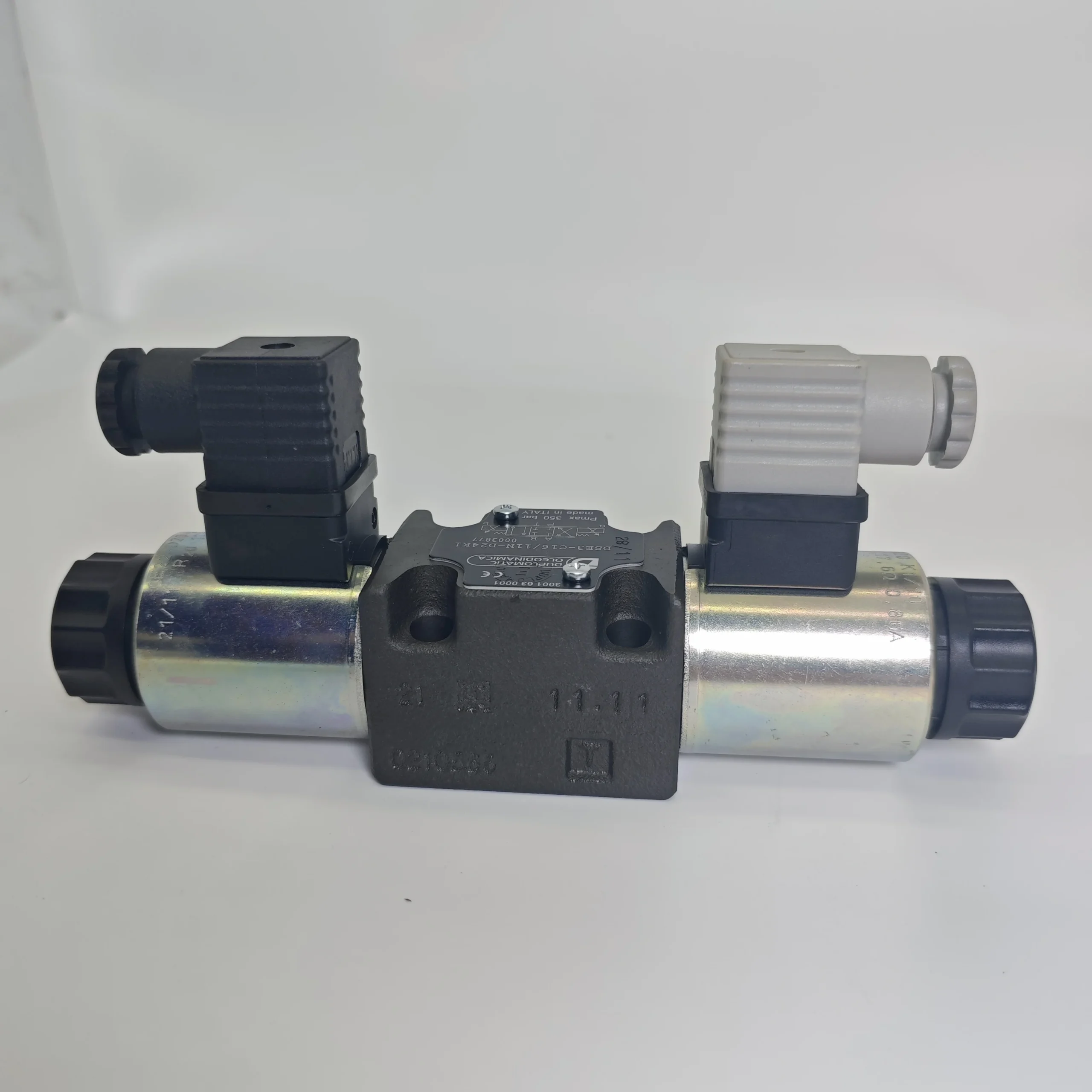
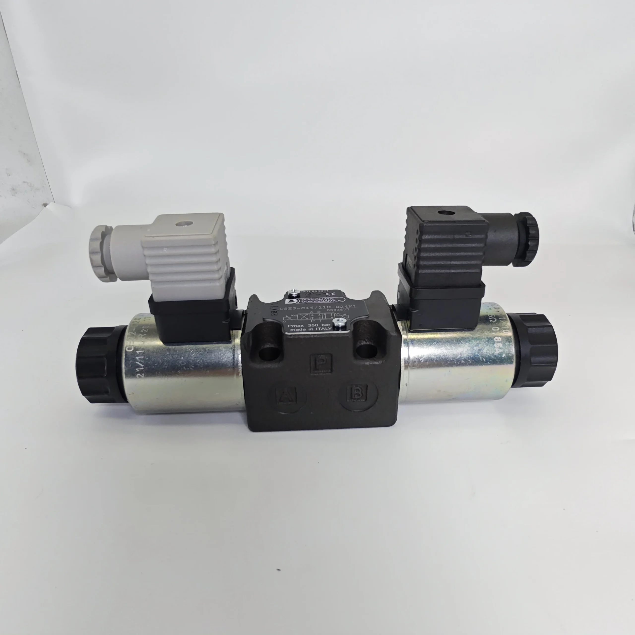
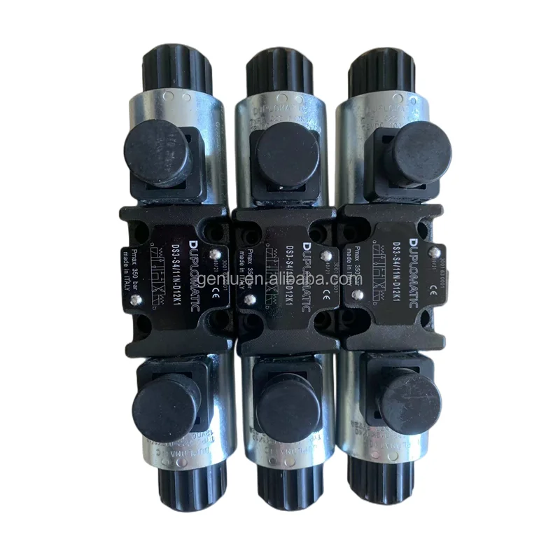
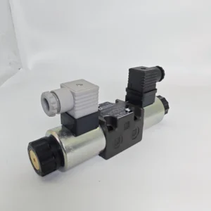
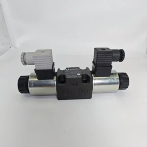
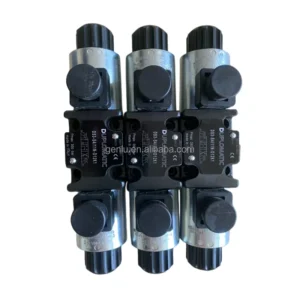
The DS5 series (including specific model codes DS5-S2/12N-A230K1, DS5-S1/12N-D24K1, and variants across DS3, DS5, DSE series) is a direct-acting solenoid operated directional control valve engineered to strict ISO 4401-05 (NG10 / CETOP 05 / NFPA D05) mounting standards. Designed as a high-performance aftermarket solution for original Duplomatic Oleodinamica valves, this product provides 100% direct drop-in interchangeability. No subplate alterations, mounting adapters, or electrical rewiring are required. Cast from heavy-duty ductile iron and integrated with micron-honed spools, the DS5 series operates at working pressures up to 320 bar with exceptional volumetric efficiency and ultra-low internal leakage. Every single valve undergoes 100% simulated full-load condition testing before leaving the factory to guarantee zero-defect field performance.
Technical Specifications:
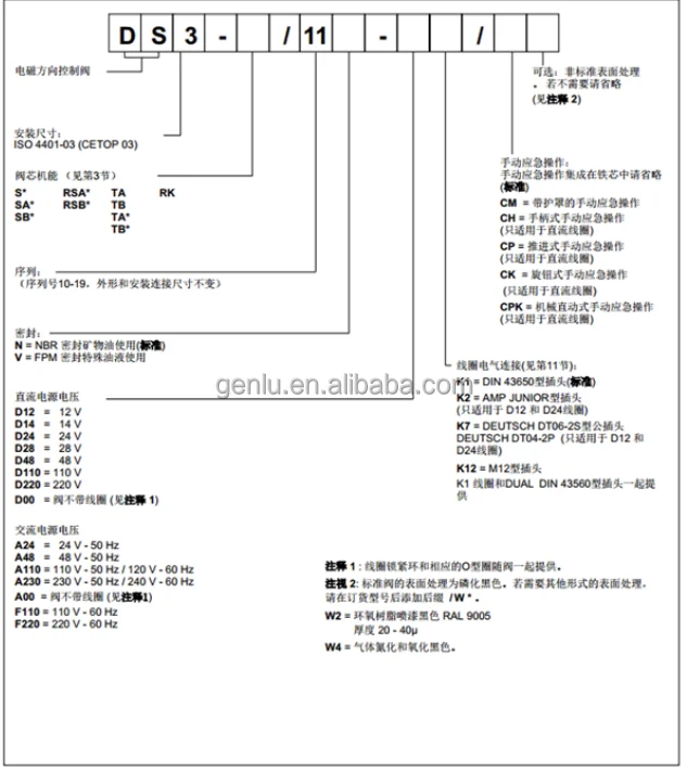
Model Codes: DS5-S2/12N-A230K1, DS5-S1/12N-D24K1 (Fully covers DS3, DS5, DSE3, DSE5 sub-variants)
Mounting Interface: ISO 4401-05-04-0-05 / CETOP 05 / NFPA D05 (NG10)
Max Operating Pressure (Ports P, A, B): 320 bar (32 MPa / 4640 psi)
Max Tank Pressure (Port T): 210 bar (DC version) / 160 bar (AC version)
Max Permissible Flow Rate: Up to 150 L/min (39.6 gpm)
Control Method: Direct-acting wet-pin solenoid operated
Coil Voltage & Connector: 24V DC (D24K1) / 230V AC (A230K1) with DIN 43650 / ISO 4400 connectors (K1)
Fluid & Temp Range: Mineral-based hydraulic oils, -20°C to +80°C
Net Weight: Approx. 3.8 kg (Single Solenoid) / 4.8 kg (Double Solenoid)
Key Technical Advantages:
100% Direct Drop-in Interchangeability: Porting layout, flange dimensions, and connector profiles strictly align with OEM Duplomatic specifications. Field replacements are effortless and instant, eliminating piping rework and minimizing equipment downtime.
Heavy-Duty Housing & Precision Honing: Cast from high-strength resin-sand ductile iron, the body withstands extreme pressure impulses. Precision compound honing between spool and body bore ensures micron-level clearances, suppressing internal bypass at full 320 bar pressure.
Durable Wet-Pin Solenoid Architecture: Features wet-pin solenoids where the armature operates submerged in system hydraulic fluid. This delivers continuous self-lubrication, efficient heat dissipation, cushioned switching impacts, and IP65 protection rating.
100% Full-Condition Simulation Testing: We reject batch sampling. Every valve is verified on automated test benches under maximum rated pressure (320 bar), full flow rates, and high-frequency switching cycles to eliminate early-life failure or spool binding before delivery.
Application Areas:
CNC machine tools, cutting platforms, and automated clamping systems
Plastic injection molding machinery and blow molding auxiliary circuits
Industrial Hydraulic Power Units (HPUs) and centralized pump stations
Scrap metal balers, hydraulic shears, and mobile hydraulic machinery
Expert Maintenance Tips:
Verify Subplate Surface Flatness: Prior to mounting, inspect the mating subplate surface. Ensure surface flatness is within 0.01/100 mm with a surface roughness better than Ra 0.8. Uneven surfaces cause mechanical stresses that can bind the internal spool when torqued.
Enforce Strict Cleanliness Standards: Solid contamination is the primary cause of spool scoring and binding. Maintain hydraulic fluid cleanliness to ISO 4406 class 20/18/15 or cleaner using high-efficiency pressure and return line filtration.
Related Models:
DS3-RK/10N-A110K1
DS3-RK/10N-A230K1
DS3-RK/10N-D24K1 C.C.
DS3-RK/10N-D110K1 C.C.
DS3-S1/10N-A230K1
DS3-S1/10N-A110K1
DS3-S1/10N-D12K1/CM
DS3-S1/10N-D24K1
DS3-S2/10N-A230K1
DS3-S2/10N-A110K1
DS3-S2/10N-D12K1/CM
DS3-S2/10N-D24K1
DS3-S3/10N-A230K1
DS3-S3/10N-A110K1
DS3-S3/10N-D12K1/CM
DS3-S3/10N-D24K1
DS3-S4/10N-A110K1
DS3-S4/10N-D12K1/CM
DS3-S4/10N-D24K1
DS3-SA1/10N-A230K1
DS3-SA1/10N-D24K1
DS3-SA2/10N-A230K1
DS3-SA2/10N-D24K1
DS3-SA2/10N-D12K1/CM
DS3-SB1/10N-A230K1
DS3-SB1/10N-A110K1
DS3-SB7/10N-D110K1
DS3-SB7/10N-A110K1
DS3-TA/10N-A230K1
DS3-TA/10N-A110K1
DS3-TA/10N-D24K1
DS3-TB/10N-A230K1
DS3-TB/10N-D24K1
DS3-TB23/10N-A00 SENZA BOB.
DS5-RK/10N-A230K1
DS5-RK/10N-A110-50K1 DUPLOM.
DS5-RK/10N-A230-50K1 DUPLOM.
DS5-RK/10N-D24K1 DUPLOM.
DS5-RK/11N-D00 SENZA BOB.C.C
DS5-RK/11N-D00 SENZA BOB.C.C
DS5-S1/12N-A00 SENZA BOB.C.A .
DS5-S1/12N-A110-50K1 DUPLOM.
DS5-S1/12N-A230-50K1 DUPLOM.
DS5-S1/12N-A24-50K1 DUPLOM.
DS5-S1/12N-D00 SENZA BOB. CC
DS5-S1/10N-D12K1 DUPLOM.
DS5-S1/10N-D24K1 DUPLOM.
DS5-S1/11N-A00 SENZA BOB.C.A
DS5-S1/11N-A00 SENZA BOB.C.A
DS5-S1/11N-A110K1 DUPLOM.
DS5-S1/11N-D00 SENZA BOB. CC
DS5-S1/11N-D00 SENZA BOB. CC
DS5-S1/11N-D12K1 DUPLOM.
DS5-S1/11N-D24K1 DUPLOM.
DS5-S1/12N-A00 SENZA BOB.C.A.
DS5-S1/12N-A00 SENZA BOB.C.A.
DS5-S11/11N-D24K1 DUPLOM.
DS5-S11/12N-D00
DS5-S2/10N-A110-50K1 DUPLOM.
DS5-S2/10N-A230-50K1 DUPLOM.
DS5-S2/10N-D00 SENZA BOB.C.C
DS5-S2/10N-D12K1 DUPLOM.
DS5-S2/10N-D24K1 DUPLOM.
DS5-S20/12N-D12K1
DS5-S20/12N-D12K1
DS5-S3/10N-A110-50K1 DUPLOM.
DS5-S3/10N-A230-50K1 DUPLOM.
DS5-S3/10N-D00 SENZA BOB.C.C
DS5-S3/10N-D110K1 DUPLOM.
DS5-S3/10N-D110K1 DUPLOM.
DS5-S3/10N-D12K1 DUPLOM.
DS5-S3/10N-D24K1 DUPLOM.
DS5-S3/10N-D24K1/F08 DUPLOM.
DS5-S3/11N-A00-CA SENZA BOB.
DS5-S3/11N-A00-CA SENZA BOB.
DS5-S3/11N-A230K1
DS5-S3/11N-D00 SENZA BOB.C.C
DS5-S3/11N-D00 SENZA BOB.C.C
DS5-S3/11N-D12K1 DUPLOM.
DS5-S3/11N-D24K1 DUPLOM.
DS5-S3/12N-A00 SENZA BOB.C.A
DS5-S4/10N-A00 SENZA BOB.C.A
DS5-S4/10N-A110-50K1 DUPLOM.
DS5-S4/10N-A230-50K1 DUPLOM.
DS5-S4/10N-D00 SENZA BOB. CC
DS5-S4/10N-D12K1 DUPLOM.
DS5-S4/10N-D24K1 DUPLOM.
DS5-S4/11N-A00 SENZA BOB.C.A .
DS5-S4/11N-A00 SENZA BOB.C.A .
DS5-S4/12N-D00-CC SENZA BOB
DS5-S4/12N-D00-CC SENZA BOB
DS5-S6/10N-A110-50K1 DUPLOM.
DS5-S6/11N-D24K1 DUPLOM.
DS5-S6/12N-D00
DS5-S6/12N-D00
DS5-S7/10N-A110-50K1 DUPLOM.
DS5-S7/10N-A110-50K1 DUPLOM.
DS5-S7/11N-A00 SENZA BOB.C.A
DS5-S7/11N-A00 SENZA BOB.C.A
DS5-S8/10N-A00 SENZA BOB.C.A
DS5-S8/10N-A00 SENZA BOB.C.A
DS5-S9/12N-D00
DS5-S9/12N-D00
DS5-SA1/10N-A00 SENZA BOB.CA
DS5-SA1/10N-A00 SENZA BOB.CA
DS5-SA1/10N-D00 SENZA BOB CC
DS5-SA1/10N-D00 SENZA BOB CC
DS5-SA1/11N-D24K1 DUPLOM.
DS5-SA2/10N-D12K1 DUPLOM.
DS5-SA2/11N A00 SENZA BOBINE
DS5-SA2/11N A00 SENZA BOBINE
DS5-SA2/11N-D12K1 DUPLOM.
DS5-SA2/11N-D12K1 DUPLOM.
DS5-SA2/12N-D00 SENZA BOB. C .C.
DS5-SA2/12N-D00 SENZA BOB. C .C.
DS5-SA2/12N-D24K1 DUPLOM.
DS5-SB1/10N-D00 SENZA BOB.CC
DS5-SB1/10N-D00 SENZA BOB.CC
DS5-SB1/11N-A00 SENZA BOB.CA
DS5-SB1/11N-A00 SENZA BOB.CA
DS5-SB1/11N-A110K1 C.A.
DS5-SB1/11N-D24K1 DUPLOM.
DS5-SB1/11N-D24K1 DUPLOM.
DS5-SB1/12N-D00 SENZA BOB.CC
DS5-SB1/12N-D00 SENZA BOB.CC
DS5-SB1/12N-D24K1 DUPLOM.
DS5-SB2/11N-D00 SENZA BOB.CC
DS5-SB2/11N-D00 SENZA BOB.CC
DS5-SB2/11N-D24K1 DUPLOM.
DS5-SB2/11N-D24K1 DUPLOM.
DS5-SB3/12N-D00 SENZA BOB.CC
DS5-SB3/12N-D00 SENZA BOB.CC
DS5-SB3/12N-D24K1 DUPLOM.
DS5-TA/10N-A00 SENZA BOB.C.A
DS5-TA/10N-A00 SENZA BOB.C.A
DS5-TA/10N-A110-50K1 DUPLOM.
DS5-TA/10N-A230-50K1 DUPLOM.
DS5-TA/10N-A24-50K1 DUPLOM.
DS5-TA/10N-D00 SENZA BOB.C.C
DS5-TA/10N-D12K1 DUPLOM.
DS5-TA/10N-D24K1 DUPLOM.
DS5-TA/10N-D24K1/F08 DUPLOM.
DS5-TA/11N-A00 SENZA BOB.C.A
DS5-TA/11N-D00 SENZA BOB.C.C
DS5-TA/11N-D00 SENZA BOB.C.C
DS5-TA/11N-D24K1
DS5-TA02/11N-D12K1Vii. Precautions for Use
1. Medium and Selection managementStrictly use compressed air that has been dried and filtered. A three-piece set (filter + pressure reducing valve + oil mist lubricator) must be installed at the air inlet to ensure that the oil content, dew point and cleanliness of the gas meet the standards. It is strictly prohibited to introduce liquid media such as hydraulic oil and water into the valve body to prevent the aging of the sealing parts.
DS3-RK/10N-A230K1
DS3-RK/10N-D24K1 C.C.
DS3-RK/10N-D110K1 C.C.
DS3-S1/10N-A230K1
DS3-S1/10N-A110K1
DS3-S1/10N-D12K1/CM
DS3-S1/10N-D24K1
DS3-S2/10N-A230K1
DS3-S2/10N-A110K1
DS3-S2/10N-D12K1/CM
DS3-S2/10N-D24K1
DS3-S3/10N-A230K1
DS3-S3/10N-A110K1
DS3-S3/10N-D12K1/CM
DS3-S3/10N-D24K1
DS3-S4/10N-A110K1
DS3-S4/10N-D12K1/CM
DS3-S4/10N-D24K1
DS3-SA1/10N-A230K1
DS3-SA1/10N-D24K1
DS3-SA2/10N-A230K1
DS3-SA2/10N-D24K1
DS3-SA2/10N-D12K1/CM
DS3-SB1/10N-A230K1
DS3-SB1/10N-A110K1
DS3-SB7/10N-D110K1
DS3-SB7/10N-A110K1
DS3-TA/10N-A230K1
DS3-TA/10N-A110K1
DS3-TA/10N-D24K1
DS3-TB/10N-A230K1
DS3-TB/10N-D24K1
DS3-TB23/10N-A00 SENZA BOB.
DS5-RK/10N-A230K1
DS5-RK/10N-A110-50K1 DUPLOM.
DS5-RK/10N-A230-50K1 DUPLOM.
DS5-RK/10N-D24K1 DUPLOM.
DS5-RK/11N-D00 SENZA BOB.C.C
DS5-RK/11N-D00 SENZA BOB.C.C
DS5-S1/12N-A00 SENZA BOB.C.A .
DS5-S1/12N-A110-50K1 DUPLOM.
DS5-S1/12N-A230-50K1 DUPLOM.
DS5-S1/12N-A24-50K1 DUPLOM.
DS5-S1/12N-D00 SENZA BOB. CC
DS5-S1/10N-D12K1 DUPLOM.
DS5-S1/10N-D24K1 DUPLOM.
DS5-S1/11N-A00 SENZA BOB.C.A
DS5-S1/11N-A00 SENZA BOB.C.A
DS5-S1/11N-A110K1 DUPLOM.
DS5-S1/11N-D00 SENZA BOB. CC
DS5-S1/11N-D00 SENZA BOB. CC
DS5-S1/11N-D12K1 DUPLOM.
DS5-S1/11N-D24K1 DUPLOM.
DS5-S1/12N-A00 SENZA BOB.C.A.
DS5-S1/12N-A00 SENZA BOB.C.A.
DS5-S11/11N-D24K1 DUPLOM.
DS5-S11/12N-D00
DS5-S2/10N-A110-50K1 DUPLOM.
DS5-S2/10N-A230-50K1 DUPLOM.
DS5-S2/10N-D00 SENZA BOB.C.C
DS5-S2/10N-D12K1 DUPLOM.
DS5-S2/10N-D24K1 DUPLOM.
DS5-S20/12N-D12K1
DS5-S20/12N-D12K1
DS5-S3/10N-A110-50K1 DUPLOM.
DS5-S3/10N-A230-50K1 DUPLOM.
DS5-S3/10N-D00 SENZA BOB.C.C
DS5-S3/10N-D110K1 DUPLOM.
DS5-S3/10N-D110K1 DUPLOM.
DS5-S3/10N-D12K1 DUPLOM.
DS5-S3/10N-D24K1 DUPLOM.
DS5-S3/10N-D24K1/F08 DUPLOM.
DS5-S3/11N-A00-CA SENZA BOB.
DS5-S3/11N-A00-CA SENZA BOB.
DS5-S3/11N-A230K1
DS5-S3/11N-D00 SENZA BOB.C.C
DS5-S3/11N-D00 SENZA BOB.C.C
DS5-S3/11N-D12K1 DUPLOM.
DS5-S3/11N-D24K1 DUPLOM.
DS5-S3/12N-A00 SENZA BOB.C.A
DS5-S4/10N-A00 SENZA BOB.C.A
DS5-S4/10N-A110-50K1 DUPLOM.
DS5-S4/10N-A230-50K1 DUPLOM.
DS5-S4/10N-D00 SENZA BOB. CC
DS5-S4/10N-D12K1 DUPLOM.
DS5-S4/10N-D24K1 DUPLOM.
DS5-S4/11N-A00 SENZA BOB.C.A .
DS5-S4/11N-A00 SENZA BOB.C.A .
DS5-S4/12N-D00-CC SENZA BOB
DS5-S4/12N-D00-CC SENZA BOB
DS5-S6/10N-A110-50K1 DUPLOM.
DS5-S6/11N-D24K1 DUPLOM.
DS5-S6/12N-D00
DS5-S6/12N-D00
DS5-S7/10N-A110-50K1 DUPLOM.
DS5-S7/10N-A110-50K1 DUPLOM.
DS5-S7/11N-A00 SENZA BOB.C.A
DS5-S7/11N-A00 SENZA BOB.C.A
DS5-S8/10N-A00 SENZA BOB.C.A
DS5-S8/10N-A00 SENZA BOB.C.A
DS5-S9/12N-D00
DS5-S9/12N-D00
DS5-SA1/10N-A00 SENZA BOB.CA
DS5-SA1/10N-A00 SENZA BOB.CA
DS5-SA1/10N-D00 SENZA BOB CC
DS5-SA1/10N-D00 SENZA BOB CC
DS5-SA1/11N-D24K1 DUPLOM.
DS5-SA2/10N-D12K1 DUPLOM.
DS5-SA2/11N A00 SENZA BOBINE
DS5-SA2/11N A00 SENZA BOBINE
DS5-SA2/11N-D12K1 DUPLOM.
DS5-SA2/11N-D12K1 DUPLOM.
DS5-SA2/12N-D00 SENZA BOB. C .C.
DS5-SA2/12N-D00 SENZA BOB. C .C.
DS5-SA2/12N-D24K1 DUPLOM.
DS5-SB1/10N-D00 SENZA BOB.CC
DS5-SB1/10N-D00 SENZA BOB.CC
DS5-SB1/11N-A00 SENZA BOB.CA
DS5-SB1/11N-A00 SENZA BOB.CA
DS5-SB1/11N-A110K1 C.A.
DS5-SB1/11N-D24K1 DUPLOM.
DS5-SB1/11N-D24K1 DUPLOM.
DS5-SB1/12N-D00 SENZA BOB.CC
DS5-SB1/12N-D00 SENZA BOB.CC
DS5-SB1/12N-D24K1 DUPLOM.
DS5-SB2/11N-D00 SENZA BOB.CC
DS5-SB2/11N-D00 SENZA BOB.CC
DS5-SB2/11N-D24K1 DUPLOM.
DS5-SB2/11N-D24K1 DUPLOM.
DS5-SB3/12N-D00 SENZA BOB.CC
DS5-SB3/12N-D00 SENZA BOB.CC
DS5-SB3/12N-D24K1 DUPLOM.
DS5-TA/10N-A00 SENZA BOB.C.A
DS5-TA/10N-A00 SENZA BOB.C.A
DS5-TA/10N-A110-50K1 DUPLOM.
DS5-TA/10N-A230-50K1 DUPLOM.
DS5-TA/10N-A24-50K1 DUPLOM.
DS5-TA/10N-D00 SENZA BOB.C.C
DS5-TA/10N-D12K1 DUPLOM.
DS5-TA/10N-D24K1 DUPLOM.
DS5-TA/10N-D24K1/F08 DUPLOM.
DS5-TA/11N-A00 SENZA BOB.C.A
DS5-TA/11N-D00 SENZA BOB.C.C
DS5-TA/11N-D00 SENZA BOB.C.C
DS5-TA/11N-D24K1
DS5-TA02/11N-D12K1Vii. Precautions for Use
1. Medium and Selection managementStrictly use compressed air that has been dried and filtered. A three-piece set (filter + pressure reducing valve + oil mist lubricator) must be installed at the air inlet to ensure that the oil content, dew point and cleanliness of the gas meet the standards. It is strictly prohibited to introduce liquid media such as hydraulic oil and water into the valve body to prevent the aging of the sealing parts.
Select the type based on the cylinder diameter (recommended ≤ 63mm), working pressure (0.1- 1.0MPa) and flow requirement. Overpressure use is strictly prohibited (> 1.2MPa May cause the valve body to rupture). If it is used in vacuum scenarios (< 0.1 MPa), a dedicated vacuum solenoid valve must be selected and cannot be directly replaced.
2. Installation and commissioning
Before installation, confirm the direction of the gas path (P for intake, A/B for working ports, R/S for exhaust ports). It is strictly forbidden to connect them in reverse (reverse connection will cause the cylinder to act in the opposite direction). When installing in a plate type, a sealing gasket should be added between the valve and the installation plate, and the tightening torque should be controlled at 8-10 N·m to prevent air leakage.
Before debugging, blow the gas line with compressed air for 3 to 5 minutes to remove iron filings and dust in the pipeline. The power-on test response time (≤15 ms is normal), manually press the emergency button to confirm that the valve core switches smoothly without jamming. Adjust the pressure reducing valve to stabilize the working pressure at 0.4-0.6 MPa.
The installation location should be far away from high-temperature heat sources (such as heaters) and strong magnetic field equipment to prevent coil aging or control signal interference. When installed outdoors, a rain cover should be added to ensure that the protection level remains at IP65.
3. Operation and Maintenance
During operation, check the valve body for air leakage once a week (apply soapy water to the interface; no bubbles are normal), coil temperature (normal ≤50℃, maximum ≤60℃), and exhaust noise. In case of air leakage, response delay or coil overheating, stop the machine immediately for inspection, with a focus on checking the wear of the seals or the filtration condition of the air source.
Regular maintenance every six months: Disassemble the valve body, clean impurities from the valve core and valve cavity; Check the wear condition of the sealing lip (replace it when it is aged or damaged); Apply silicon-based grease to the manual button and reset spring, and test the airtightness after reassembly.
It is strictly prohibited to keep the power on for a long time without ventilation (more than 1 hour may cause the coil to burn out). It is strictly prohibited to strike the valve body or valve core with hard objects (as it may cause deformation and jamming of the valve core). Before the equipment is shut down, the gas source should be cut off to release the residual pressure in the valve body, and then the power supply should be disconnected.
4. Storage protection
When stored for a long time, all interfaces should be sealed with dedicated plugs, and the coil terminal blocks should be sealed with insulating caps. Store in a dry warehouse with a temperature ranging from 0 to 40℃ and a humidity of no more than 60%. Avoid direct sunlight, heavy object compression and corrosive gas erosion. Power on and test the coil performance once every three months.
Before putting the valve into use after being idle for more than six months, thoroughly clean the valve cavity and replace the aged sealing parts. Low-pressure air (0.2 MPa) is introduced to test the flexibility of the valve core’s operation, and power is applied to check the response performance. Only after meeting the standards can it be connected to the system for use.