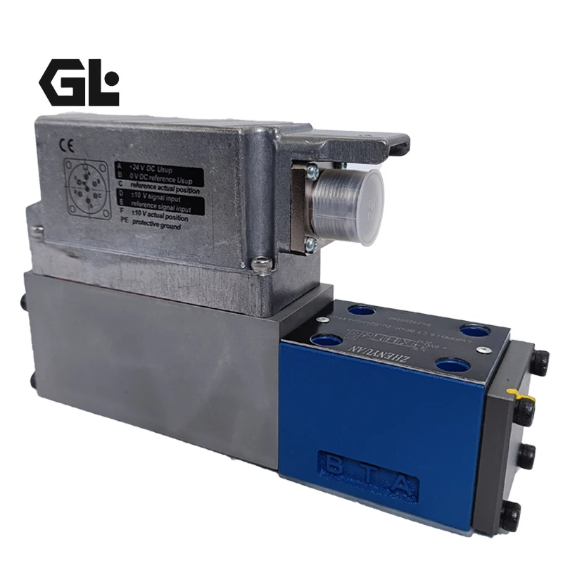
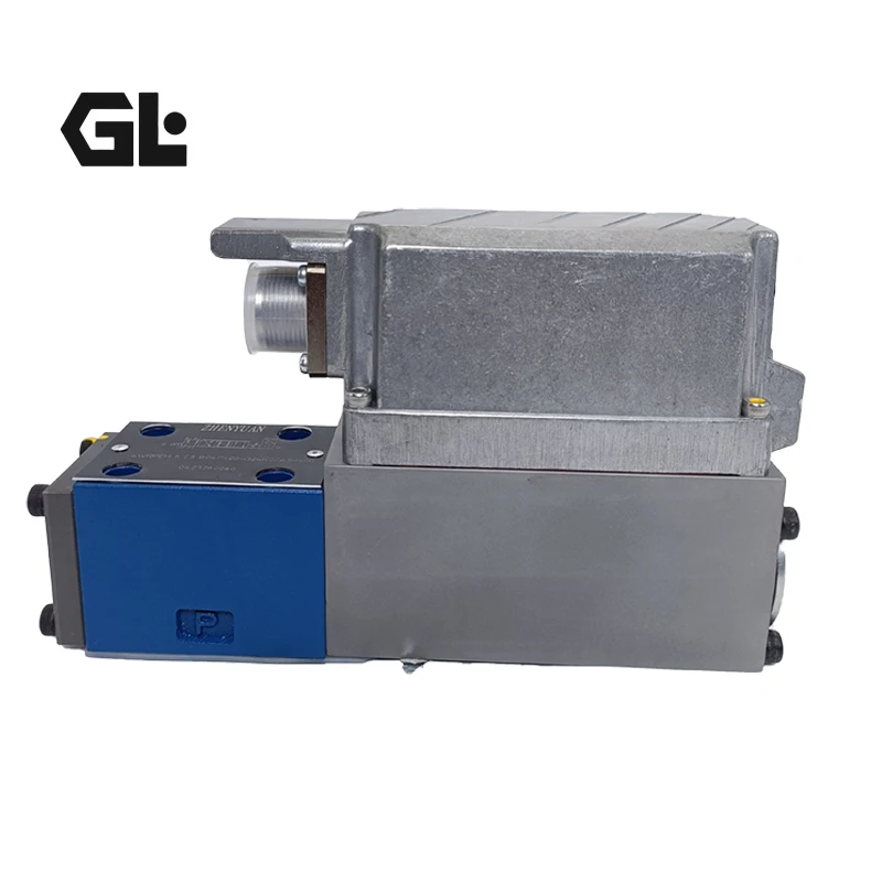
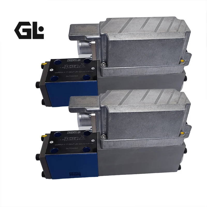
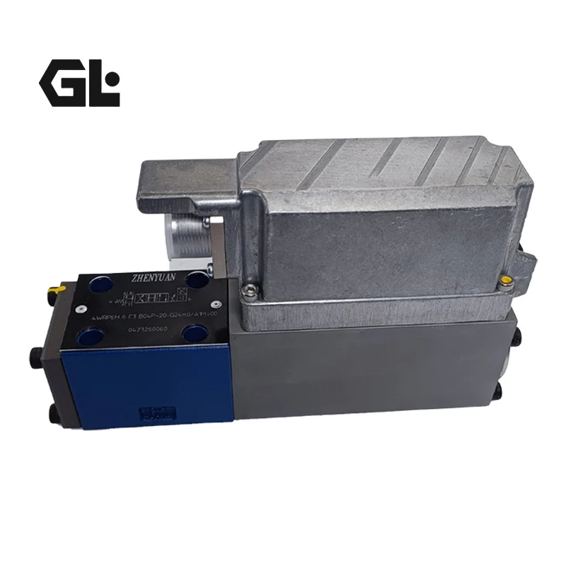
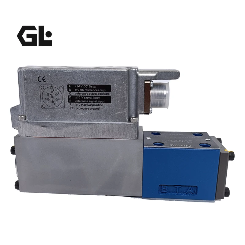
Hydraulic Proportional Directional Valve 4WRPEH 4WRPEH 6 Series 4WRPEH 6 C3 B40L-2X/G24K0/A1M 4WRPEH 10C4 B50L-2X/G24K0
| Model Number | 4WRPEH 6 C3 B40L-2X/G24K0/A1M, 4WRPEH 10 C4 B50L-2X/G24K0 |
|---|
Product Description
Hydraulic Proportional Directional Valve 4WRPEH 4WRPEH 6 Series 4WRPEH 6 C3 B40L-2X/G24K0/A1M 4WRPEH 10C4 B50L-2X/G24K0

The 4WRPEH 6C3 B40L-2X /G24K0/A1M is a direct-acting high-frequency response directional control valve with electrical position feedback and integrated electronic components. It is commonly used in high-precision hydraulic control scenarios in fields such as construction machinery, machine tools, and plastic machinery. The following is a detailed explanation from multiple dimensions. The specific content is as follows:
Model Analysis
The order code rules for the 4WRPEH series, and the meanings of each segment of this model are as follows:
The specific meanings of model segments
The number 4 indicates that the valve has four main oil ports, which are compatible with the layout of the oil inlet, outlet and return circuits in a conventional hydraulic system.
WRP stands for Direct-acting Directional Control Valve, which does not require pilot oil to drive. It is a core structural symbol of this series and has the advantage of energy conservation.
The E-marked valve is equipped with an integrated electronic component (OBE), which enables the processing of control signals and closed-loop feedback regulation of the valve core position.
H indicates that the control valve core and valve sleeve are designed with servo-level quality, ensuring high-precision flow and direction control and reducing regulation lag.
6 represents the valve specification and size, corresponding to a specific installation interface and flow rating. The rated flow of this specification covers 4-40L/min (∆p=35bar/control side).
C3 refers to the valve core function, corresponding to the specific hydraulic oil on-off logic and intermediate position state, and is adapted to the load control requirements under specific working conditions.
B represents the installation side of the inductive position sensor, clearly indicating the assembly orientation of the sensor to ensure the stability of position signal collection.
40 represents the rated flow parameter, which corresponds to a rated flow of 40L/min here (∆p=35bar/control edge, when bent by 40%).
L indicates that the flow characteristic is linear, and the displacement of the valve core is directly proportional to the flow rate, which is convenient for achieving smooth flow regulation.
2X is the component series code, corresponding to the component series within the range of 30 to 39, marking the unified standard for installation and connection dimensions.
G24 refers to the power supply type of integrated electronic components being 24V DC voltage, which is compatible with the general electrical power supply system in the industrial field.
K0 is the auxiliary code for the control interface and electromagnet, indicating specific wiring methods and electromagnet drive parameters, and is suitable for basic control scenarios.
A1 indicates that the control value input type is ±10V analog signal, which can precisely receive instruction signals from external control systems to achieve high-precision regulation.
The sealing material marked with M is NBR rubber, which is compatible with conventional hydraulic oil media and has excellent sealing performance and compatibility.
Product attributes
The specific content of the attribute category
The core type is a direct-acting high-frequency response directional control valve with electrical position feedback and integrated electronic components
Key parameters: Maximum working pressure 350bar, rated flow 40L/min (∆p=35bar/control side); The ambient temperature adaptation range is -20 ℃ to +60℃, and the transportation and storage temperature range is -30 ℃ to +80℃
The valve body is made of high-strength valve body materials. The valve core and valve sleeve are of servo-grade steel structure, and the sealing parts are made of NBR material
The installation and interface adopt base plate installation, and the oil port installation surface complies with ISO 4401 standard. The control signal interface is a ±10V analog input
The medium is compatible with conventional hydraulic oil. It is necessary to ensure that the oil cleanliness meets the system control requirements. It is recommended to use a 10μm filter element with βₙ≥200
Working principle
This valve achieves precise regulation through closed-loop control integrating electronic components and the valve core. The integrated electronic component (OBE) will compare the preset control value with the actual position value of the valve core in real time. When a control deviation occurs, the travel coil will be activated immediately. The magnetic force of the coil varies with the deviation signal, pushing the valve core to overcome the spring force and generate displacement. The displacement of the valve core is proportional to the input signal, and then the flow rate and direction of the hydraulic oil are regulated by changing the size of the throttling cross-section. When the control value is preset to 0V, the electronic components will adjust the valve core to overcome the spring to the center position. In case of power failure or other fault situations, the spring returns to its relaxed state, and the valve core automatically switches to the fault-safe position (closed state) to prevent unexpected load actions.
Product features
High control accuracy: The valve core and valve sleeve are of servo-grade quality, combined with linear flow characteristics and inductive position feedback, with a response speed of the millisecond level and a small lag. It can meet the precise control requirements of high-speed mechanical movements, such as the action regulation of the feed mechanism in machine tools.
Safe and reliable: Equipped with a fail-safe design, the valve core automatically resets to a safe closed position when faults such as power failure or low voltage occur. Made of high-quality materials and with advanced manufacturing processes, it is wear-resistant and corrosion-resistant, and can operate stably for a long time under harsh working conditions.
Energy-saving and flexible: No pilot oil supply is required, making it more energy-efficient compared to traditional two-stage valves. It supports multi-dimensional control of position, rate and pressure. It can also be equipped with accessories such as vibration damping plates and electronic component protective films to adapt to different working environments.
Easy maintenance: The structural design is simple, and key components such as coils can be disassembled and replaced separately. Supports the optional IO-Link interface, which is convenient for fault detection and parameter debugging, and can reduce maintenance time and cost.
Installation and operation
Installation specification: The installation surface shall comply with the ISO 4401 standard, with a plane roughness of ≤Ra 3.2μm and a flatness difference of ≤0.02mm/m. It is rigidly fixed through the threaded holes at the bottom. It is recommended to install a 1.5mm thick vibration damping gasket to absorb vibration. Electrical connections should use shielded twisted-pair cables with a diameter of ≥0.75mm². Signal lines should be independently run through metal pipes, with a distance of ≥200mm from power cables. The shielding layer should be grounded at one end to prevent interference. In scenarios with high air humidity and large temperature differences, electronic component protective films can be installed to prevent condensation water from damaging the components.
Operation requirements: Before operation, it is necessary to ensure that the cleanliness of the system oil meets the high standards corresponding to NAS 1638. A 10μm filter element with βₙ≥200 should be installed at the oil inlet to prevent impurities from wearing the valve core and valve sleeve. During operation, monitor the temperature of the valve body. Under normal working conditions, it should be controlled within 65℃ to prevent high temperatures from affecting the sealing performance and the lifespan of electronic components. When restarting after shutdown, first power on without load to check if the displacement of the valve core is normal, and then gradually increase the pressure to the working pressure to avoid component impact damage caused by starting under pressure.
A complete list of 4WRPEH 6 series products
This series of products mainly forms detailed models through differences in valve core functions, flow parameters, control interfaces, etc. Common complete models are as follows:
4WRPEH 6 C3 B40L – 2X/G24K0/A1M
4WRPEH 6 C4 B40L – 3X/M/24A1
4WRPEH 6 C1 B12L – 2X/G24K0/F1V
4WRPEH 6 C5 B25L – 2X/G24K0/A1M
4WRPEH 6 C3 B04L – 2X/G24K0/A1V
4WRPEH 6 C4 B24L – 3X/G24K0/L1
4WRPEH 6 C1 B15L – 2X/G24K0/C6
4WRPEH 6 C5 B40L – 2X/G24K0/A1M
4WRPEH 6 C3 B25L – 3X/G24K0/F1M
4WRPEH 6 C4 B04L – 2X/G24K0/A1VThe 4WRPEH 6 series is a plate-mounted hydraulic valve with a diameter of 6. The installation surface strictly adheres to the ISO 4401 standard (specifically corresponding to ISO 4401-03-02 or ISO 4401-05-04 and other detailed specifications), and is suitable for the installation benchmark of industrial general hydraulic valves. The core installation dimensions and related specifications are sorted out as follows in combination with industry manuals and parameters of similar products (all units are mm) :
Key dimensions of the installation surface and installation holes
This series adopts a base plate type installation. The layout and diameter of the installation holes are the core parameters for installation adaptation. Among them, the relevant dimensions of the installation holes are 4 installation holes with a maximum diameter of 7.5mm, and at the same time, there are 4 auxiliary holes with a diameter of 5.5mm. The distribution and spacing of the hole positions are adapted to the standard layout of ISO 4401 with a diameter of 6. The flatness of the installation surface needs to meet the accuracy requirement of 0.01mm/100mm. The surface roughness of the plane is ≤Ra 3.2μm to ensure the sealing performance after installation and prevent the leakage of hydraulic oil.
Dimensions of the valve body and accessory structures
The outer diameter dimensions of the valve body vary by different parts. The outer diameter range of some key parts is 9.4-11.8mm, while that of some other structures is 12.7-13.5mm, which is suitable for the reserved space of the corresponding installation base plate.
In the installation associated dimensions of the integrated amplification board, electromagnet and other accessory structures, the specification of the matching O-ring is 9.25×1.78, which is used for sealing the P, A, B and T oil ports to ensure the sealing performance after the oil ports are in contact with the installation surface.
Other installation adaptation sizes
This series is suitable for working conditions with a rated flow rate of 4-40L /min. During installation, it is necessary to match the oil circuit interface corresponding to the flow rate grade. The layout of the oil ports should conform to the conventional hydraulic circuit design with four main oil ports. When installing, no additional space for the pilot oil interface needs to be reserved. Moreover, the installation side of the inductive position sensor is marked as Type B, and space for sensor assembly should be reserved to avoid interference with other hydraulic components.
If precise details such as the center distance of the installation holes and the total length of the valve body are required, you can refer to the official technical manual of this series of Bosch Rexroth, or compare with the standard size detail drawing of ISO 4401 with a diameter of 6 to ensure a complete match with the installation base plate.
Company Profile


Frequently Asked Questions
1.What ls our Main Products?
1.Hydraulic pump
2.Hydraulic valve
3.Hydraulic motor
4.Hydraulic cylinder
5.Hydraulic parts
2. What about the MOQ?
3.What are your advantages?
- Adhere to quality first.
- Support customization, ODM & OEM service.
- 1-year warranty and complete after-sales support.
- Safe and fast shipping worldwide.
- 24-hour online service for your inquiries.
4.Are you a manufacturer? What’s your delivery time?
Yes, we are a manufacturer with our own factory.
Common models are in stock, and orders are usually shipped within 1–3 days.
5.Which payment methods are accepted?
We accept T/T, L/C, PayPal, VISA, Western Union, Apple Pay, Google Pay, Afterpay (Clearpay), Klarna, and Trade Assurance.
For full orders: 30% deposit, balance before shipment.
For small/sample orders: full payment in advance.
6.How will you deliver my goods?
We offer flexible shipping options: DHL, UPS, FedEx, TNT, EMS, as well as air or sea freight.
All deliveries ensure door-to-door fast and safe service.
7.How do you inspect and guarantee your products?
All products are tested before shipment to ensure perfect working condition.
We offer a 12-month warranty — if a product fails due to quality issues, we provide free spare parts or repair support.
8.What about after-sales service?
If you encounter any problem during use, please contact your sales manager or our support team at any time.
We will respond quickly and help solve the issue efficiently.
9.What are your main applications?
- Hydraulic systems
- Agricultural machinery
- Construction machinery
- Automobile industry
- Local distributors and maintenance centers
10.Can I get a discount for bulk orders?
Yes. We offer competitive wholesale prices and try our best to give benefits to long-term partners.
Shoot Us An Email
Professional Manufacturer


