Product Overview
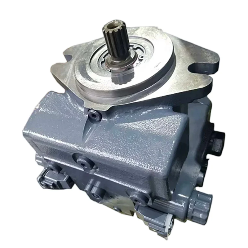
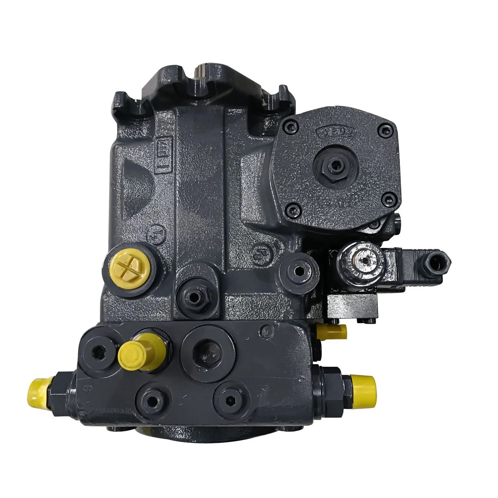
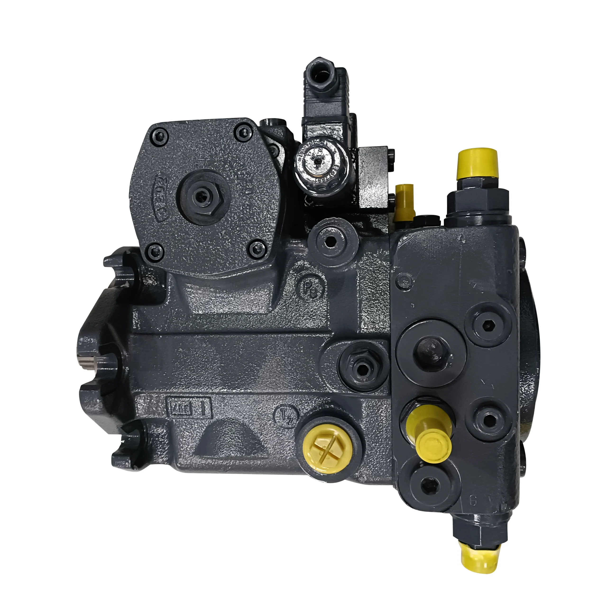
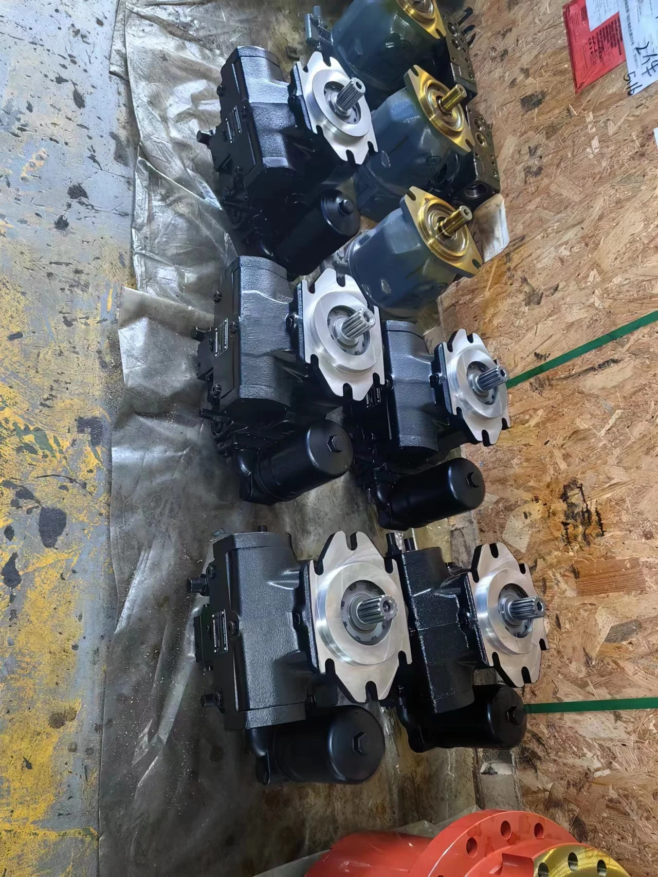
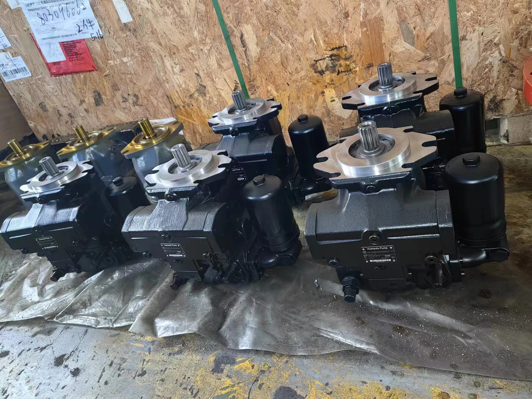
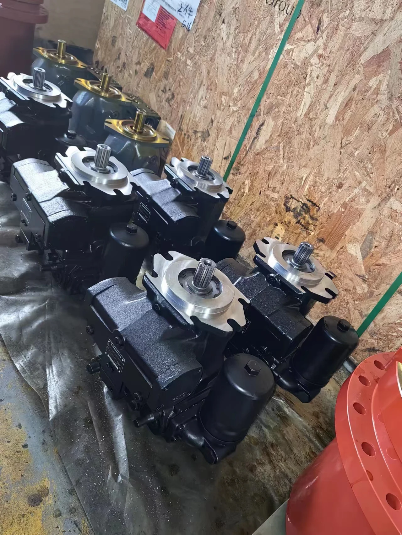
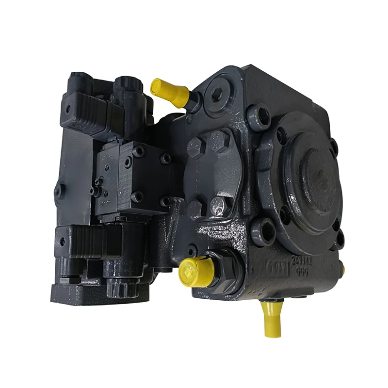
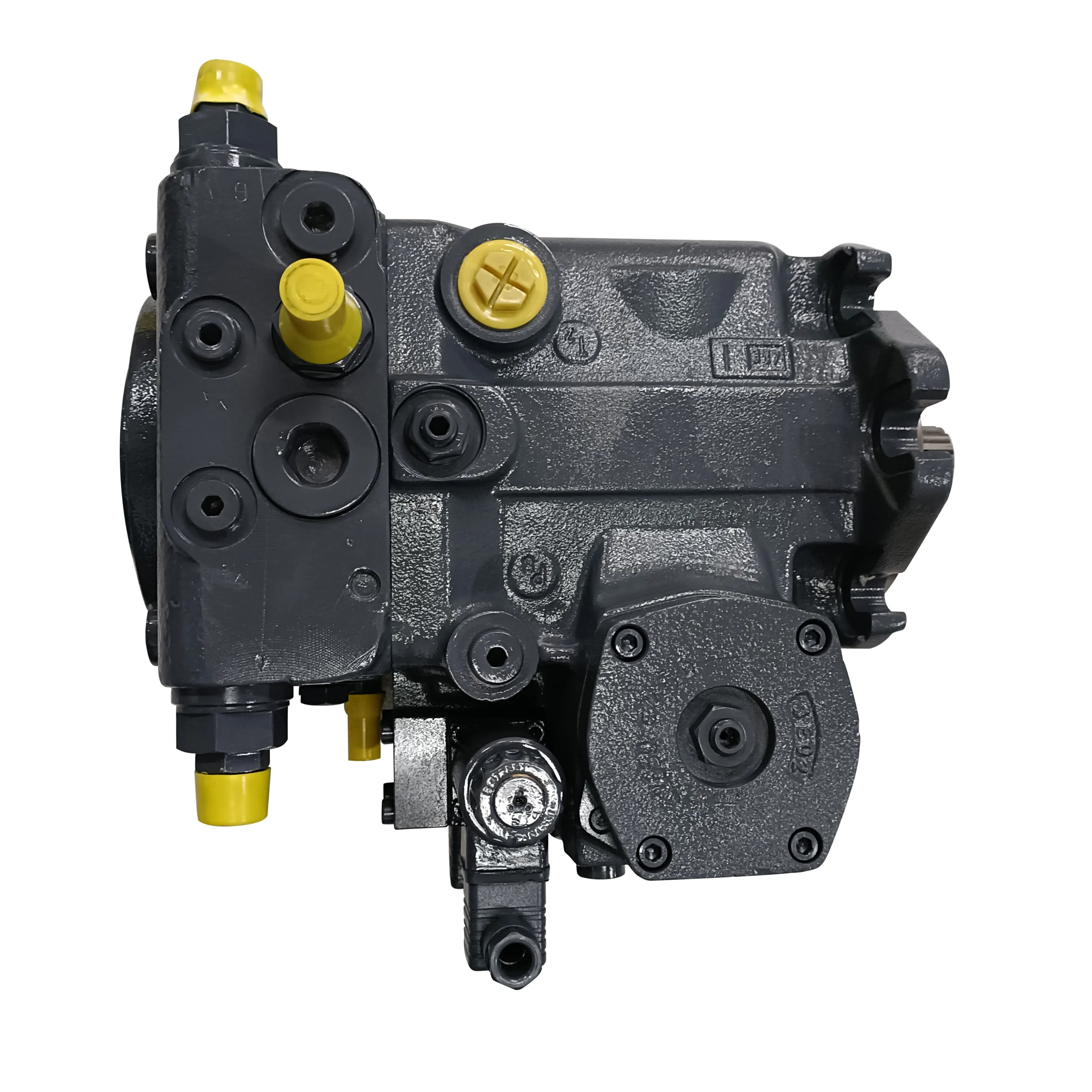
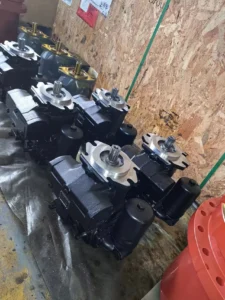
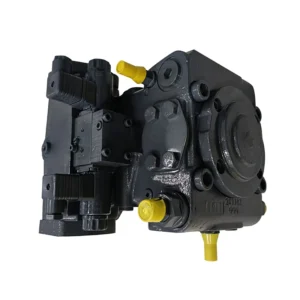
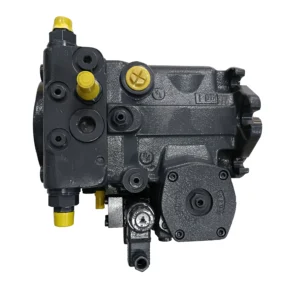
The A4VG90DA2D2/32L-NZF02F0418H and A4VG125EP4DM1/32R-NZF02N00XEH-S are the 90 cc-class and 125 cc-class core models within the Bosch Rexroth A4VG series 32 of swashplate axial piston variable displacement pumps. The A4VG series is Rexroth’s flagship platform for closed-circuit hydrostatic transmissions, spanning displacements from 28 to 250 cm³/rev with a nominal pressure of 400 bar and peak pressure of 450 bar (up to 550 bar for certain configurations), widely deployed in construction machinery travel drives, concrete mixer drum drives, and industrial hydraulic systems.
The A4VG series features a swashplate design where flow is proportional to drive speed and displacement and is infinitely variable. The pump is equipped with two pressure-relief valves on the high pressure ports to protect the hydrostatic transmission from overload, with the high-pressure relief valves also functioning as boost valves. The integrated boost pump acts as a feed and control oil pump, with maximum boost pressure limited by a built-in boost pressure relief valve. The integral pressure cut-off is standard across the range.
Model Code Breakdown (for procurement and engineering reference):
A4VG90DA2D2/32L-NZF02F0418H:
A4VG: Rexroth closed-circuit swashplate axial piston variable pump
90: Nominal size (NG), geometric displacement 90 cm³/rev
DA: Automatic Control, Speed Related — automatically adjusts pump displacement by detecting inlet damping pressure differential changes, maintaining optimal matching between pump torque and engine output torque to prevent engine stall under overload
2D2: Control variant code
/32L: Series 32, counterclockwise rotation (viewed from shaft end)
NZF02F0418H: N = NBR seals; ZF = shaft configuration; 02 = design variant; F0418H = factory calibration code
A4VG125EP4DM1/32R-NZF02N00XEH-S:
A4VG: Rexroth closed-circuit swashplate axial piston variable pump
125: Nominal size (NG), geometric displacement 125 cm³/rev
EP4: Electric Proportional Control with proportional solenoids, 24V supply, pump displacement proportional to solenoid current signal (200–600 mA)
DM1: Control variant code
/32R: Series 32, clockwise rotation (viewed from shaft end)
NZF02N00XEH-S: N = NBR seals; ZF = shaft configuration; 02 = design variant; N00 = standard configuration; XEH = additional configuration code; S = seal material designation
DA Control Function Details:
DA is an automatic control, speed related, specifically designed for hydrostatic travel drive systems used in combination with the variable motor A6VM. The DA valve detects inlet damping pressure differential changes, amplifies the output control pressure to balance the valve sleeve, and directs output pressure through a 3/4-way directional valve to control the variable piston, driving the swashplate rotation for pump displacement control. The automatic regulating function of the DA valve always maintains optimal matching between axial piston pump torque and engine output torque, preventing engine stall under overload and improving system efficiency.
EP4 Control Function Details:
EP4 is an electro-hydraulic proportional control method. Electrical energy is converted to force acting on the control spool through proportional solenoids. Pump output flow is infinitely varied in the range of 0 to 100%, proportional to an electrical current in the range of 200–600 mA at 24 VDC. EP4 control uses proportional valve direct control of the stroking piston, offering simple structure and strong contamination resistance. As the stroking piston moves, it drives the feedback lever to rotate around a fixed pivot, which in turn drives the servo balance lever to oscillate, achieving precise closed-loop displacement control.
Drop-in Replacement Advantage: Manufactured to exact Rexroth OEM specifications, these pumps achieve complete drop-in interchangeability with the original A4VG series 32 for SAE J744 mounting flange, shaft dimensions, SAE main port layout, and control module interface. Every pump undergoes 100% simulated load testing prior to shipment, validating 400 bar pressure loading, control response, and volumetric efficiency under conditions replicating real-world duty cycles.
Technical Specifications
A4VG90 Series General Specifications:
Series: Rexroth A4VG Series 32 (Closed Circuit, Swashplate Design)
Nominal Size: NG 90
Geometric Displacement (Variable Pump): 90 cm³/rev
Auxiliary Pump Displacement (p = 20 bar): 19.6 cm³/rev
Nominal Pressure: 400 bar (continuous)
Peak Pressure: 450 bar (intermittent)
Continuous Maximum Speed (nnom): 3050 rpm
Intermittent Maximum Speed (nmax): 3800 rpm
Minimum Speed: 500 rpm
Maximum Flow (nnom, Vg max): 275 L/min
Maximum Power (Δp = 400 bar): 183 kW
Maximum Torque (Vg max, Δp = 400 bar): 573 N·m
Moment of Inertia: 0.0149 kgm²
Housing Material: High-strength cast iron
Seal Material: NBR, suitable for mineral oil-based hydraulic fluid
Weight: Approx. 60 kg
Through Drive Capability: Supports mounting of subsequent pumps of same or smaller size
Model A4VG90DA2D2/32L-NZF02F0418H Configuration:
Model Code: A4VG90DA2D2/32L-NZF02F0418H
Control Type: DA — Automatic Control, Speed Related
Rotation: Counterclockwise (viewed from shaft end, L code)
Series: 32
Factory Calibration: NZF02F0418H configuration
A4VG125 Series General Specifications:
Series: Rexroth A4VG Series 32 (Closed Circuit, Swashplate Design)
Nominal Size: NG 125
Geometric Displacement (Variable Pump): 125 cm³/rev
Auxiliary Pump Displacement (p = 20 bar): 28.3 cm³/rev
Nominal Pressure: 400 bar (continuous)
Peak Pressure: 450 bar (intermittent), up to 550 bar for certain configurations
Continuous Maximum Speed (nnom): 2850 rpm
Intermittent Maximum Speed (nmax): 3450 rpm
Minimum Speed: 500 rpm
Maximum Flow (nnom, Vg max): 356 L/min
Maximum Power (Δp = 400 bar): 238 kW
Maximum Torque (Vg max, Δp = 400 bar): 796 N·m
Moment of Inertia: 0.0232 kgm²
Housing Material: High-strength cast iron
Seal Material: NBR, suitable for mineral oil-based hydraulic fluid
Weight: Approx. 80 kg
Through Drive Capability: Supports mounting of subsequent pumps of same or smaller size
Model A4VG125EP4DM1/32R-NZF02N00XEH-S Configuration:
Model Code: A4VG125EP4DM1/32R-NZF02N00XEH-S
Control Type: EP4 — Electric Proportional Control, 24V proportional solenoid driven
Control Current Range: 200–600 mA
Rotation: Clockwise (viewed from shaft end, R code)
Series: 32
Factory Calibration: NZF02N00XEH-S configuration
A4VG Series Displacement Size Reference:
A4VG28: 28 cm³/rev, nnom 4250 rpm, flow 119 L/min, power 79 kW, weight 29 kg
A4VG40: 40 cm³/rev, nnom 4000 rpm, flow 160 L/min, power 107 kW, weight 31 kg
A4VG56: 56 cm³/rev, nnom 3600 rpm, flow 202 L/min, power 134 kW, weight 38 kg
A4VG71: 71 cm³/rev, nnom 3300 rpm, flow 234 L/min, power 156 kW, weight 50 kg
A4VG90: 90 cm³/rev, nnom 3050 rpm, flow 275 L/min, power 183 kW, weight 60 kg
A4VG125: 125 cm³/rev, nnom 2850 rpm, flow 356 L/min, power 238 kW, weight 80 kg
A4VG180: 180 cm³/rev, nnom 2500 rpm, flow 450 L/min, power 300 kW
A4VG250: 250 cm³/rev, nnom 2400 rpm, flow 600 L/min, power 400 kW
Key Technical Advantages
1. DA Speed-Related Automatic Control with Engine Power Matching
The A4VG90DA2D2/32L-NZF02F0418H is equipped with the DA automatic controller, which detects inlet damping pressure differential changes, amplifies output control pressure to balance the valve sleeve, and directs output pressure through a 3/4-way directional valve to control the variable piston, driving swashplate rotation for automatic displacement adjustment. The automatic regulating function of the DA valve always maintains optimal matching between axial piston pump torque and engine output torque, preventing engine stall under overload and improving system efficiency. DA control is particularly suitable for hydrostatic travel drive systems used in combination with the variable motor A6VM, with wide application in construction machinery travel drives.
2. EP4 Electric Proportional Control with Precise Displacement Regulation
The A4VG125EP4DM1/32R-NZF02N00XEH-S is equipped with the EP4 electro-hydraulic proportional control module, driven by a 24V proportional solenoid with a control current range of 200–600 mA. Pump output flow is infinitely varied in the range of 0 to 100%, proportional to the current signal. EP4 control uses proportional valve direct control of the stroking piston, offering simple structure, low manufacturing cost, and strong contamination resistance. As the stroking piston moves, it drives the feedback lever to rotate around a fixed pivot, which in turn drives the servo balance lever to oscillate, achieving precise closed-loop displacement control, particularly suitable for mobile equipment applications requiring remote or automated displacement control.
3. Integrated Boost Pump with Closed-Circuit Protection System
The A4VG series incorporates an integrated boost pump with a displacement of 19.6 cm³/rev for size 90 and 28.3 cm³/rev for size 125 (at p = 20 bar), serving as both feed pump and control oil pump. The pump is equipped with two pressure-relief valves on the high pressure ports to protect the hydrostatic transmission from overload. The high-pressure relief valves also function as boost valves. Maximum boost pressure is limited by a built-in boost pressure relief valve. The integral pressure cut-off is standard, automatically reducing pump displacement to zero when system pressure reaches the setpoint.
4. High-Strength Cast-Iron Housing with Wide Temperature Adaptability
The pump body is precision-cast from high-strength cast iron, with the material’s damping characteristics effectively suppressing structural vibration and fluid-borne noise. The wide operating temperature range accommodates extreme ambient temperatures from -40°C to +90°C, particularly suitable for mobile hydraulic equipment operating outdoors and in harsh conditions. The low-inertia rotating group (0.0149 kgm² for size 90 and 0.0232 kgm² for size 125) ensures excellent system dynamic response characteristics.
5. Through Drive and Modular System Expansion
The A4VG series supports through drive, allowing direct mounting of subsequent pumps of same or smaller size on the rear of the main pump for single-motor multi-pump compound hydraulic systems. Modular control designs enable field conversion and upgrade. Standardized SAE J744 mounting flange and shaft require no adaptation for replacement, significantly reducing equipment downtime.
6. Wide Seal Compatibility with Hydraulic Fluid Adaptability
The A4VG series is designed for operation with HLP mineral oil (per DIN 51524). The seal material is NBR (nitrile rubber), with shaft seal in FKM (fluoroelastomer). System cleanliness should be maintained at ISO 4406 20/18/15 or better, with recommended viscosity range 16–36 mm²/s, meeting diverse mobile hydraulic application requirements.
Application Areas
Excavators: Excavator travel drive closed-circuit hydraulic systems (A4VG90DA and A4VG125EP4DM1 are widely used in the excavator industry)
Rotary Drilling Rigs: Rotary drilling rig travel drives and main hydraulic systems
Road Rollers: Vibratory roller travel drive hydraulic systems
Concrete Mixer Trucks: Drum drive closed-circuit hydraulic systems
Construction Equipment: Wheel loader travel drives, bulldozer hydraulic drives
Agricultural Machinery: High-horsepower tractor closed-circuit transmissions, combine harvester hydraulic drives
Mining Equipment: Mining truck hydrostatic drives, underground LHD hydraulic systems
Industrial Hydraulic Power Units: Closed-circuit hydraulic power units, test bench hydraulic systems
Expert Maintenance Tips
1. Hydraulic Fluid Cleanliness
The A4VG series DA/EP4 control spool operates with extremely tight clearances and is highly sensitive to particulate contamination. System fluid cleanliness must meet ISO 4406 20/18/15 or better. Recommended fluids are HLP mineral oils (per DIN 51524) with viscosity grades VG46 or VG68. Install a 10 μm absolute-rated filter element at the pump inlet. Replace elements at 500 hours after first commissioning, then every 1,000 operating hours or 6 months, whichever comes first.
2. DA Speed-Related Controller Commissioning
The A4VG90DA2D2/32L DA controller achieves automatic adjustment through a pilot pressure signal related to engine speed. During commissioning, confirm that the DA valve inlet damping pressure differential sensing line is correctly connected and the control pressure output range meets system requirements. The core function of the DA controller is to maintain optimal matching between pump torque and engine output torque. After commissioning, verify engine speed stability under variable load conditions, ensuring no stall occurs due to sudden load changes.
3. EP4 Proportional Solenoid Maintenance
The A4VG125EP4DM1/32R is equipped with the EP4 electric proportional control module, with a proportional solenoid supply voltage of 24V and a control current range of 200–600 mA. Regularly inspect the proportional solenoid electrical connectors for corrosion, moisture ingress, or loose pins. Verify the control current signal waveform with an oscilloscope every 2,000 hours to ensure proper PWM waveform and accurate displacement control.
4. Case Drain Line Requirements
The case drain line must return directly to the reservoir. Maximum permissible back pressure is 2 bar (0.2 MPa). The drain outlet must terminate below oil level at all times to prevent air ingestion. The drain line diameter must not be smaller than the pump case drain port size. Case drain temperature (influenced by pressure and speed) may be higher than the control temperature or circuit temperature, but the temperature at any part must not exceed 115°C.
5. Pre-Start Priming and Air Bleeding
Before first start, fill the pump housing with clean hydraulic fluid through the case drain port. After installation, turn the drive shaft by hand several revolutions to confirm free rotation without binding. Position the control at neutral (zero displacement) and run at low speed for 5–10 minutes. Verify continuous bubble-free flow from the case drain. Only after confirming adequate lubrication and boost pressure should the pump be loaded.
6. High-Pressure Relief Valve and Pressure Cut-Off Inspection
The pump’s built-in two high-pressure relief valves protect the hydrostatic transmission from overload and also function as boost valves. Inspect the relief valve setting pressure every 2,000 operating hours to confirm it remains below the 450 bar peak pressure and that the bypass function operates correctly. The integral pressure cut-off is standard; during commissioning, verify that its cut-off pressure setting is approximately 3 MPa lower than the main relief valve setting to ensure proper system protection.