
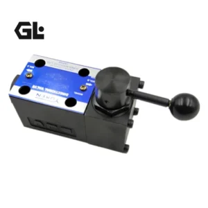
Product Overview
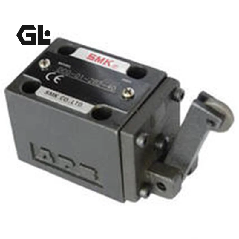
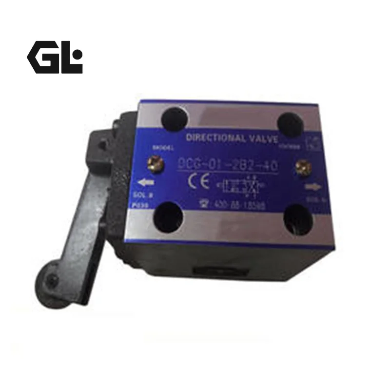
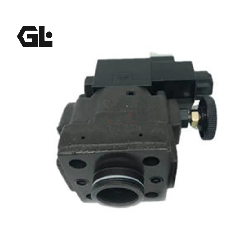
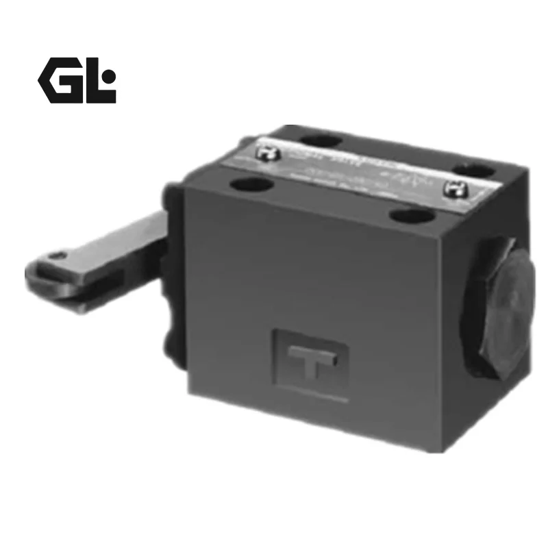
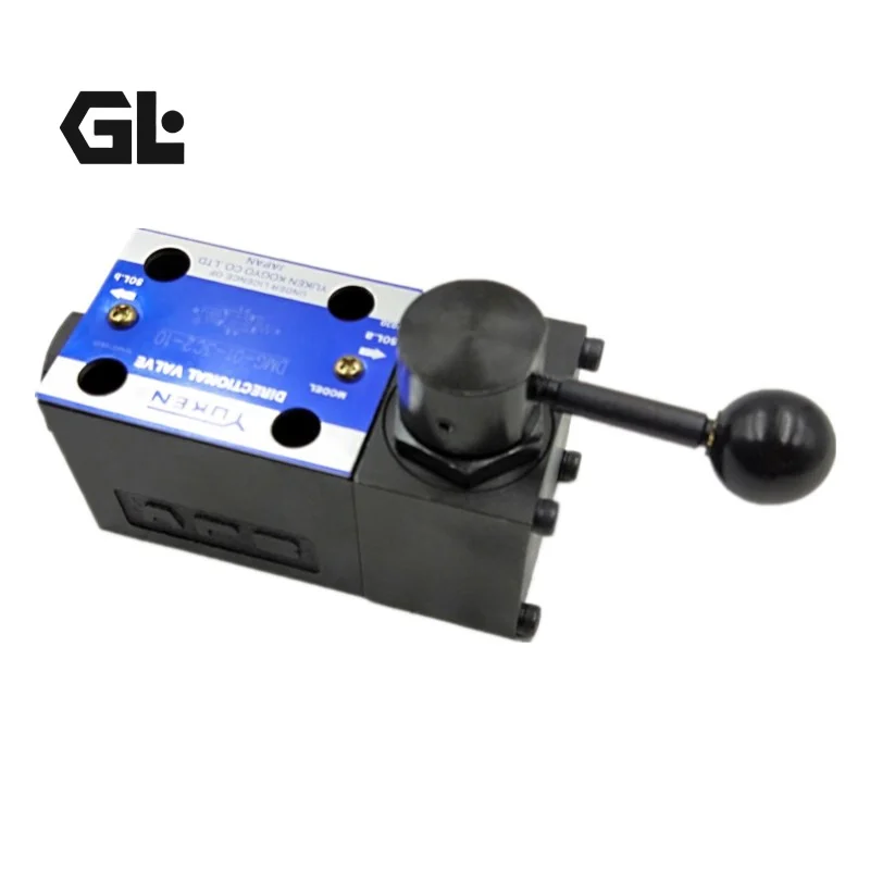
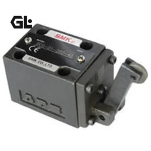
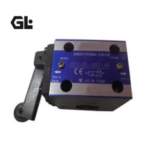
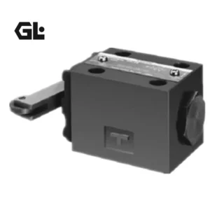
The DCG-01-2B2-40 / DCG-03-2B2-50 / DCG-01-2B2-X-40 / DCG-03-2B2-50T / DCG-03-2B2-R-50 are cam-operated (mechanically actuated) directional valves from the Yuken DCT/DCG Series. These valves shift the direction of oil flow by depressing the spool via a cam mechanism, making them ideal for pilot circuit control, actuator directional control, and applications where space is limited.
The DCT series features threaded connections, while the DCG series features subplate mounting—both offer identical performance with different connection methods. The valve body employs a spool-type design with precision O-ring sealing for minimal internal leakage. DCG series valves conform to ISO 4401 (CETOP) international mounting standards.
Every unit supplied undergoes 100% simulated real-world condition testing to guarantee reliable shifting performance under rated pressure and flow. The product offers drop-in interchangeability, requiring no modifications for direct replacement of Yuken original components.
Technical Specifications (Bulleted List)
Note: The following parameters are compiled based on publicly available technical data for the Yuken DCT/DCG Series.
DCG-01 Series (6mm Nominal Size)
Product Series: DCT/DCG Series Cam Operated Directional Valves
Connection Type: DCG = Subplate Mounting
Valve Size (Nominal Diameter): 01 = 6mm
Number of Positions: 2 = 2-position
Spring Configuration: B = Spring Return
Spool Type: 2 = Standard (P→A / B→T in neutral)
Cam Roller Position: Y = Right side / R = Left side / No mark = Without roller (01 size only)
Design Number: 40 = JIS standard
Max. Working Pressure: 21 MPa (3,050 psi)
Allowable Back Pressure (T port): 7 MPa (1,020 psi)
Max. Flow Rate: 30 L/min (7.9 USGPM)
Spool Stroke: Approx. 4 mm
Body Material: Cast Iron
Weight (DCG Type): Approx. 1.1 kg
Mounting Interface: ISO 4401 compliant
Hydraulic Fluid: Mineral oil based
Fluid Viscosity: ISO VG 10~68, ISO VG 32/46 recommended
Fluid Cleanliness: NAS Class 7 or better
Operating Temperature Range: -20°C ~ +80°C
DCG-03 Series (10mm Nominal Size)
Product Series: DCT/DCG Series Cam Operated Directional Valves
Connection Type: DCG = Subplate Mounting
Valve Size (Nominal Diameter): 03 = 10mm
Number of Positions: 2 = 2-position
Spring Configuration: B = Spring Return
Spool Type: 2 = Standard (P→A / B→T in neutral)
Cam Roller Position: Y = Right side / R = Left side
Design Number: 50 = ISO standard
Max. Working Pressure: 25 MPa (3,630 psi)
Allowable Back Pressure (T port): 10 MPa
Max. Flow Rate: 100 L/min (26.4 USGPM)
Spool Stroke: Approx. 5 mm
Body Material: Cast Iron
Weight (DCG Type): Approx. 3.8 kg
Mounting Interface: CETOP D03 subplate
Hydraulic Fluid: Mineral oil based
Fluid Viscosity: ISO VG 10~68, ISO VG 32/46 recommended
Fluid Cleanliness: NAS Class 7 or better
Operating Temperature Range: -20°C ~ +80°C
Key Technical Advantages
1. Cam-Operated Mechanical Design – No Electrical Control Required
The purely mechanical cam-operated design shifts oil flow by depressing the spool via a cam mechanism. No solenoids, no electrical signals required—making it ideal for explosion-proof environments, high-temperature/high-humidity conditions, and applications where electrical control is unsuitable or space is limited.
2. Precision Spool-Type Valve – Minimal Internal Leakage & High Reliability
The spool-type design with precision O-ring sealing delivers minimal internal leakage. Tightly controlled spool-to-body clearances ensure excellent sealing performance and reliable shifting under high-pressure conditions.
3. Dual Connection Options – Flexible System Integration
The DCT series offers threaded connections while the DCG series offers subplate mounting—both deliver identical performance. Users can select the connection type that best suits their system piping design and installation space without compromising performance.
4. 90° Right-Angle Flow Passage Design – Low Pressure Drop
The 90° right-angle flow passage design effectively reduces fluid resistance and pressure loss. Pressure drop at rated flow is ≤0.3 MPa, ensuring system efficiency and response speed.
5. Selectable Cam Roller Position – Adapts to Different Cam Layouts
The 01 size offers three roller position options: Y (right side), R (left side), and no roller. Users can select the appropriate roller position based on the actual cam mechanism layout, simplifying installation design and commissioning.
Application Areas
Machine Tool Hydraulic Systems – Table reversing, clamping and unclamping control
Injection Molding Machines – Safety door interlocking and stroke control
Die-Casting Machines – Stroke reversing and sequence control
Automated Production Lines – Stroke-end signaling and actuator directional control
Packaging Machinery – Cyclic action hydraulic directional control
Explosion-Proof Hydraulic Systems – Mining, chemical, and other applications where electrical sparks are prohibited
Pilot Circuit Control – Pilot stage control for large-flow main valves
Expert Maintenance Tips
Sizing Guidelines:
Size Selection – Select the 01 size (30 L/min) or 03 size (100 L/min) based on system maximum flow rate. Exceeding rated flow will result in increased pressure drop and unreliable shifting.
Roller Position Verification – The 01 size offers Y (right), R (left), and no-roller options. Verify the cam mechanism orientation and available installation space before selection.
Spring Return Confirmation – The B series features spring return. For detent (no-spring) holding type, select the N series.
Installation Guidelines:
Mounting Surface Precision – When using a subplate, order the corresponding subplate model. When not using a subplate, the mounting surface must be machined to 6~8 grade precision.
Spool Stroke Matching – 01 size spool stroke is approx. 4mm; 03 size is approx. 5mm. When designing the cam profile, ensure the cam provides sufficient stroke to fully shift the spool—insufficient stroke will result in incomplete shifting.
Return Line Back Pressure Control – 01 size back pressure must not exceed 7 MPa; 03 size must not exceed 10 MPa. Excessive back pressure will affect spool return reliability.
Fluid Cleanliness Control – Maintain system fluid cleanliness at NAS Class 7 or better to protect spool-to-body mating surfaces from sticking and wear.
Routine Maintenance:
Periodically inspect cam-to-roller contact surface wear—excessive wear will affect spool stroke and shifting accuracy
Inspect valve body-to-subplate interface for external leakage
If shifting delay or incomplete shifting is observed, prioritize inspection of cam profile wear and spool movement smoothness
For models with monitoring switches (DCTS/DCGS series), periodically verify switch signal integrity
Related Models:
DCT-01-2B2-40
DCT-01-2B2-R-40
DCT-01-2B3-40
DCT-01-2B3-R-40
DCT-01-2B8-40
DCT-01-2B8-R-40
DCT-03-2B2-50
DCT-03-2B2-R-50
DCT-03-2B3-50
DCT-03-2B3-R-50
DCT-03-2B8-50
DCT-03-2B8-R-50
DCG-01-2B2-40
DCG-01-2B2-R-40
DCG-01-2B3-40
DCG-01-2B3-R-40
DCG-01-2B8-40
DCG-01-2B8-R-40
DCG-03-2B2-50
DCG-03-2B2-R-50
DCG-03-2B3-50
DCG-03-2B3-R-50
DCG-03-2B8-50
DCG-03-2B8-R-50
DCT-01-2B2-R-40
DCT-01-2B3-40
DCT-01-2B3-R-40
DCT-01-2B8-40
DCT-01-2B8-R-40
DCT-03-2B2-50
DCT-03-2B2-R-50
DCT-03-2B3-50
DCT-03-2B3-R-50
DCT-03-2B8-50
DCT-03-2B8-R-50
DCG-01-2B2-40
DCG-01-2B2-R-40
DCG-01-2B3-40
DCG-01-2B3-R-40
DCG-01-2B8-40
DCG-01-2B8-R-40
DCG-03-2B2-50
DCG-03-2B2-R-50
DCG-03-2B3-50
DCG-03-2B3-R-50
DCG-03-2B8-50
DCG-03-2B8-R-50