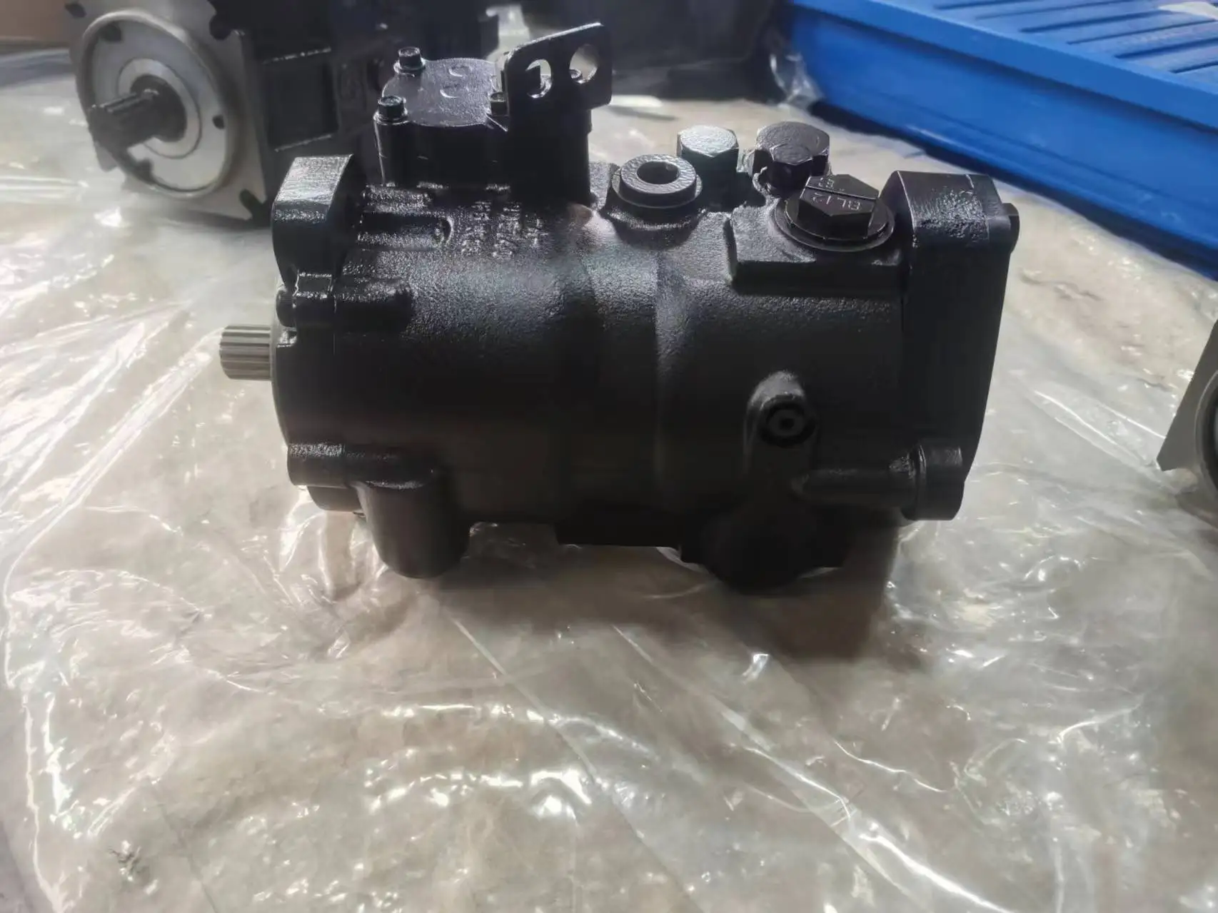
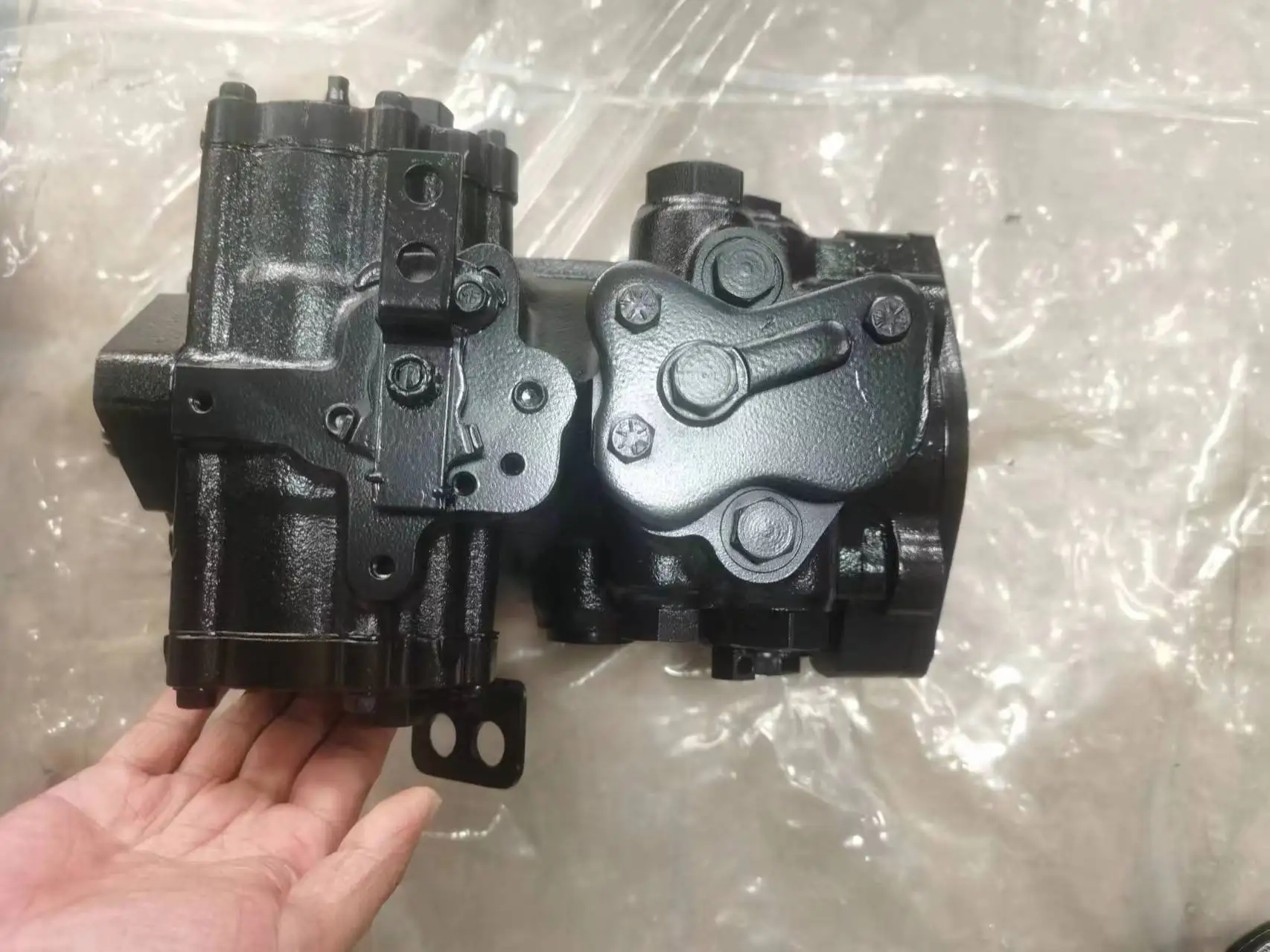
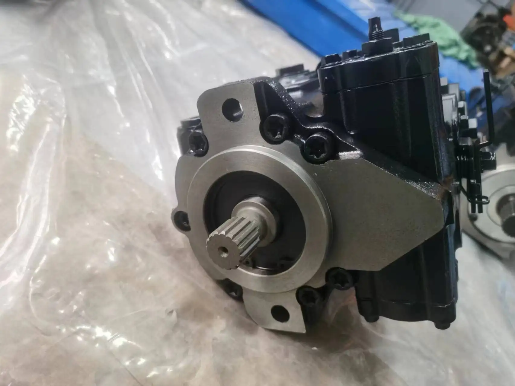
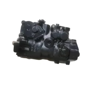
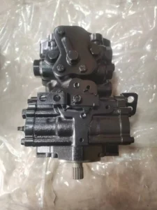
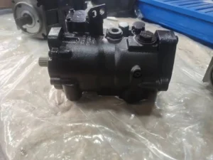
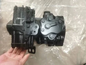
Product Overview
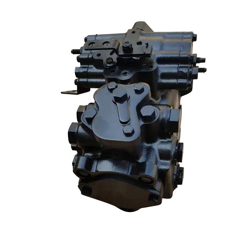
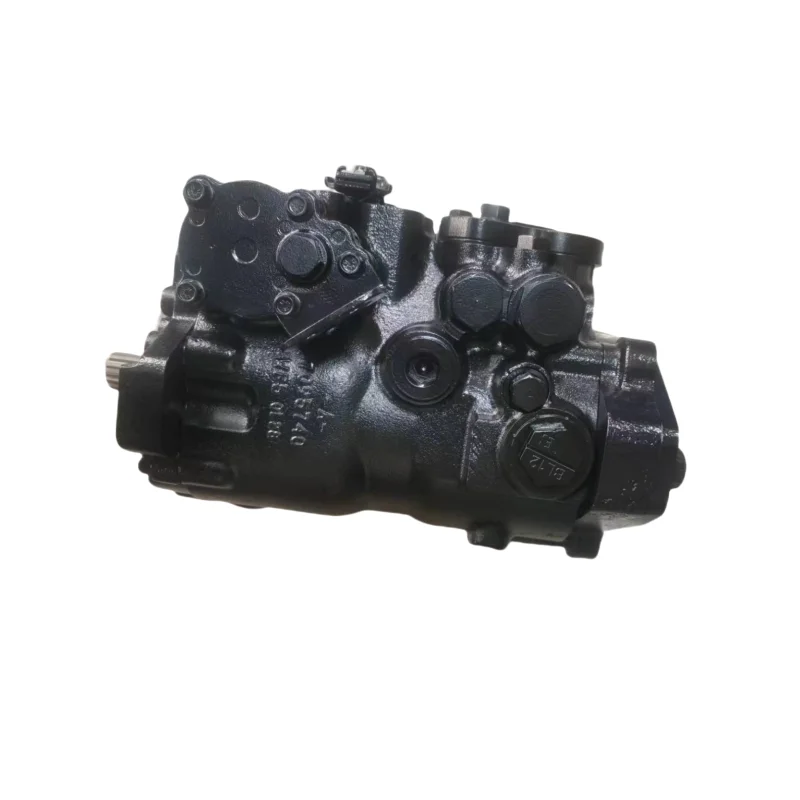
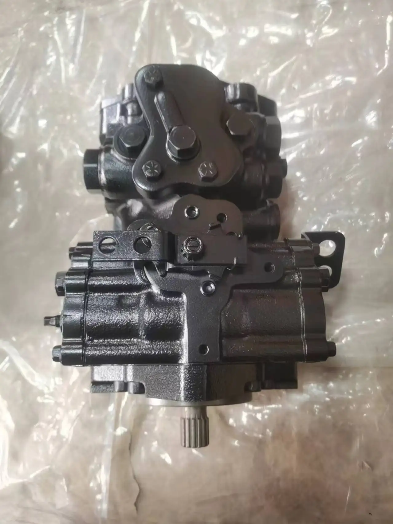
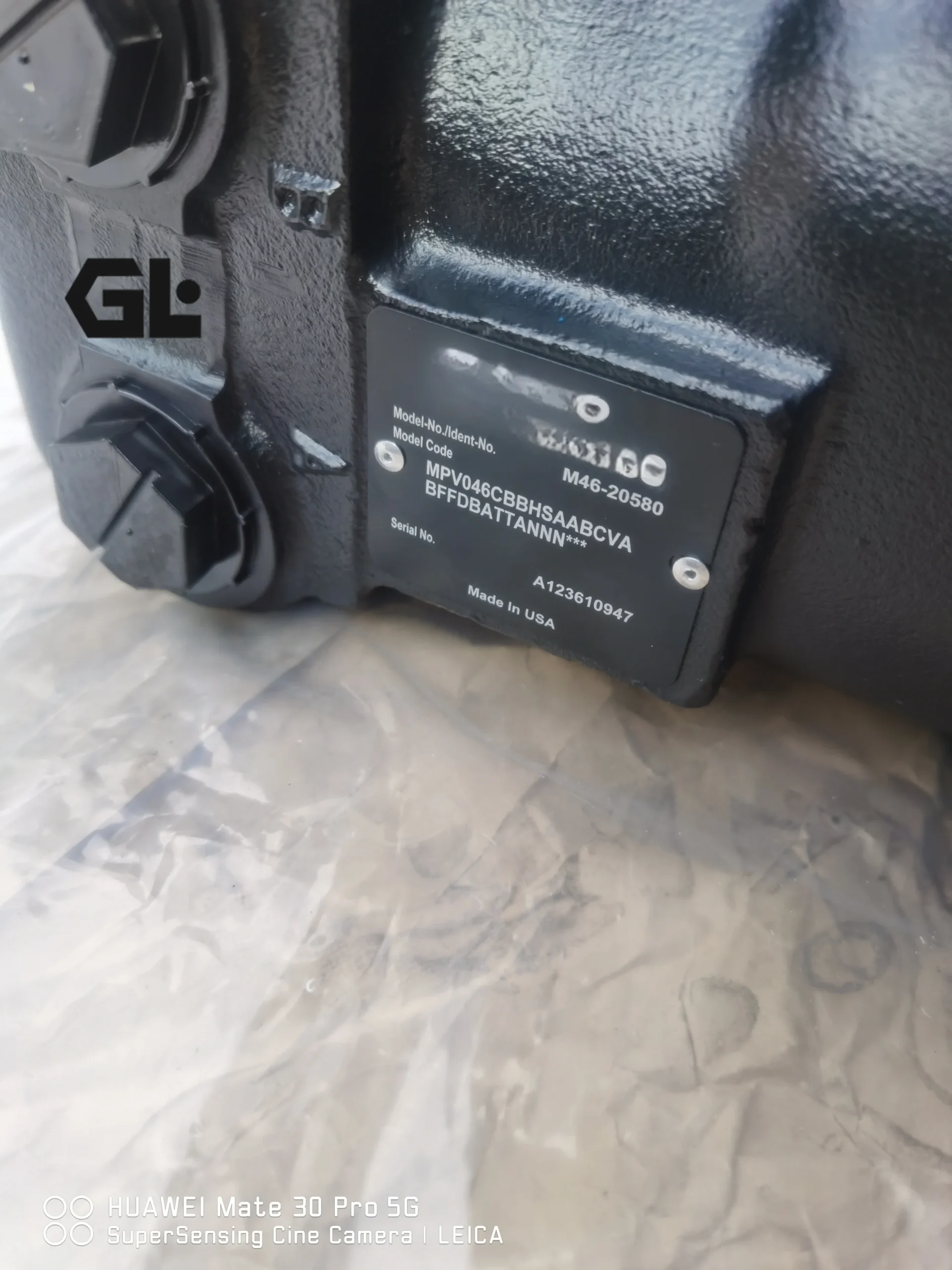
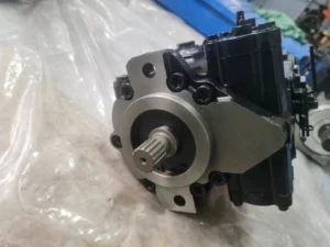
The MPV046CBAKSBBAAAABFFABUFFBNNN is a Sauer Danfoss Series 40 M46 swashplate-type axial piston variable displacement pump with a nominal displacement of 45.9 cm³/rev. Series 40 M46 pumps are purpose-designed for medium-power mobile hydraulic applications with a maximum load pressure of 345 bar (5000 psi). The pump features an integrated charge pump supplying boost flow, loop cooling, and control pressure to the closed-circuit system, with bi-directional swashplate actuation enabling continuous displacement variation in both flow directions.
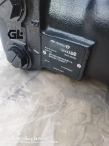
The full order code MPV046CBAKSBBAAAABFFABUFFBNNN follows the Danfoss Series 40 standard coding system. MPV indicates variable pump, 046 is the nominal displacement code (46 cm³/rev), and C denotes the pressure-balanced swashplate design. The subsequent character sequence specifies seal group, input shaft/auxiliary drive, rotation direction, charge pump displacement, charge pressure relief valve setting, filtration method, displacement limiter, bypass valve, system pressure protection, control type, handle position, control orifice diameter, auxiliary mounting pad, and special hardware features. For the precise per-character decode of this full order code, consult the Danfoss official catalog L1001029.
Manufactured to exact Sauer Danfoss M46 platform specifications, this pump delivers true drop-in interchangeability — identical mounting flange (SAE-B 2-bolt), shaft specification (splined shaft per ANSI B92.1), port positions, and displacement rating. Every unit undergoes 100% simulated operating condition testing before shipment.
Technical Specifications
The following specifications are based on Danfoss Series 40 M46 official technical data (Catalog L1001029) and publicly available configuration data:
Model: MPV046CBAKSBBAAAABFFABUFFBNNN
Manufacturer: Sauer Danfoss
Series: Series 40 M46
Design: Swashplate-type axial piston variable displacement pump, closed-circuit
Nominal Displacement: 45.9 cm³/rev (2.80 in³/rev)
System Pressure (Δp continuous): 345 bar (5000 psi)
Peak Pressure: 415 bar (6020 psi)
Maximum Speed (at rated capacity): 4000 rpm
Rotation Direction: Right hand / Left hand optional (per configuration code)
Control Type: Electrical Displacement Control (EDC), dual coil, oil-filled, MS 4-pin connector, 23–132 mA control current
Integrated Charge Pump Displacement: 13.99 cm³/rev (0.85 CIR)
Charge Pressure Relief Valve Setting: 19.5 bar (280 psi)
Filtration: Suction filtration
Mounting Flange: SAE-B 2-bolt flange
Shaft Specification: Splined shaft (ANSI B92.1, 13-tooth or 15-tooth 16/32dp, per configuration)
Displacement Limiter: Full displacement
Bypass Valve: No orifice
System Pressure Protection: 250 bar / with check valve
Auxiliary Mounting Pad: SAE-A flange
Weight (MDC without Auxiliary Pad): Approx. 33 kg (73 lb)
Seal Kit Part Number: 4510017 (MPV046 specific)
Operating Fluid: Mineral hydraulic oil
System Type: Closed-circuit hydraulic system
Key Technical Advantages
1. Precise Variable Control via Electrical Displacement Control (EDC)
The pump employs an electrical displacement control in which an electro-hydraulic Pressure Control Pilot (PCP) valve controls pilot pressure to drive the servo piston, varying the swashplate angle and enabling continuous, stepless displacement adjustment from maximum forward to maximum reverse. The dual-coil MS 4-pin connector configuration with a control current range of 23–132 mA offers fast response — ideal for closed-circuit travel drive systems requiring frequent displacement changes and precise speed control. The pressure-balanced swashplate design (C type) reduces required control effort and enhances control precision.
2. Integrated Charge Pump Simplifies Closed-Circuit Architecture
The pump integrates a charge pump with a displacement of 13.99 cm³/rev and a charge pressure relief valve setting of 19.5 bar (280 psi). The integrated charge pump simultaneously handles closed-circuit boost flow, loop cooling circulation, and control pressure supply — eliminating the need for an external standalone charge pump and associated piping, simplifying system architecture, reducing leakage risk, and saving installation space.
3. 345 bar High-Pressure Capability in a Compact Design
Series 40 M46 pumps are designed for compact packaging and high power density, delivering high-pressure output at 45.9 cm³/rev displacement and 4000 rpm speed. Continuous system pressure reaches 345 bar (5000 psi) with peak pressure of 415 bar (6020 psi), meeting the high-pressure demands of medium-power mobile hydraulic applications. The compact pump body suits installation environments with limited engine compartment space in construction and agricultural machinery.
4. Wide Speed Range and Bi-Directional Continuous Displacement
The swashplate tilts continuously in both directions, enabling stepless displacement variation from maximum forward to maximum reverse, with smooth flow direction change. Maximum speed of 4000 rpm maintains stable flow output and excellent control linearity across the operating speed range. Flow direction changes smoothly as the swashplate passes through neutral, delivering smooth reversing operation for travel drive systems.
5. 100% Simulated Operating Condition Testing
Every pump undergoes a comprehensive factory test protocol: continuous operation at 345 bar rated pressure to verify volumetric and total efficiency, peak pressure cycling to validate housing and seal integrity, and full-speed-range verification of displacement control linearity and EDC control response. Test documentation is supplied with each unit.
Application Areas
Construction Machinery: Excavator travel drive systems, wheel loader travel systems, road roller vibration and travel hydraulic drives
Agricultural Machinery: Tractor hydraulic drives, combine harvester travel systems, sprayer hydraulic drives
Material Handling Equipment: Forklift and telehandler hydraulic power systems
Municipal Vehicles: Street sweeper and garbage compactor hydraulic drive systems
Mining Equipment: Mine transport vehicles, underground LHD loader hydrostatic transmissions
Industrial Closed-Circuit Hydraulic Systems: Industrial hydrostatic drive equipment requiring precise variable control
Expert Maintenance Tips
1. EDC Electro-Hydraulic Proportional Control System Calibration and Maintenance
EDC control relies on precise matching of the electro-hydraulic Pressure Control Pilot (PCP) valve and servo piston. After pump or control module replacement, verify the control current (23–132 mA) to displacement relationship at rated speed and 50% displacement, confirming it falls within the factory calibration curve. MS 4-pin connector wiring must strictly follow the Danfoss official wiring diagram to avoid reversed connections causing control malfunction. Control signal cables should use shielded cable with single-end shield grounding to prevent electromagnetic interference affecting control precision.
2. Charge Pump Suction Line Requirements
The integrated charge pump draws oil from the reservoir. Suction line diameter must accommodate the charge pump flow demand at 4000 rpm (13.99 cm³/rev × 4000 rpm ≈ 56 L/min) to avoid negative pressure and cavitation. The suction inlet should sit at least 100 mm below the reservoir oil level. Inspect or replace the suction filter every 500 hours. Charge pressure should be maintained near the 19.5 bar setting; if charge pressure drops abnormally, immediately inspect the charge pump and relief valve.
3. Mandatory Case Pre-Fill and Air Purging
After installation, fill through the highest case port with clean hydraulic fluid filtered to ≤10 μm until oil overflows. Open the bleed plug and run the pump at idle until bubble-free oil flows continuously. For closed-circuit systems, perform low-pressure circulation with the charge pump running before applying load. Dry starting will cause catastrophic wear to the slipper and swashplate friction pair within seconds.
4. Fluid Cleanliness and Viscosity Control
Maintain system cleanliness at NAS 9 or ISO 18/16/13 or better. Optimum operating viscosity is 14–50 cSt. Suction filtration is integrated into the pump design. Replace the system return filter at 200 hours for the first interval, then inspect or replace every 500 hours.
5. Displacement Limiter and System Pressure Protection Verification
The pump is configured with a full displacement limiter and 250 bar system pressure protection (with check valve). Verify the accuracy of the pressure protection setpoint every 2000 operating hours. The displacement limiter restricts maximum pump displacement output — adjustment should follow the Danfoss official technical manual, and never exceed the system maximum pressure setting.