


A10VG45 A10VG63 Rexroth Hydraulic Piston Variable Pump
| Model Number | A10VG45EZ2DM1/10R NSC1OKO13EH-S |
|---|
SKU
N/A
Categories Hydraulic Pump, Piston Pump
Tags 12v hydraulic pump, air hydraulic pump, air pump, axial piston pump, hydraulic gear pump, hydraulic hand pump, hydraulic pump, jcb hydraulic pump, kayaba hydraulic pump, parker hydraulic pump, piston pump, pto hydraulic pump, radial piston pump, uchida hydraulic pump
Product Description
Product Overview
The A10VG45EZ2DM1/10R-NSC10K013EH-S and A10VG63EZ1DM1/10R-NSC10N003EQ-S are Bosch Rexroth A10VG series swashplate-type axial piston variable pumps engineered for hydrostatic closed-circuit transmissions. With displacements of 45 cm³/rev and 63 cm³/rev respectively, these pumps deliver infinitely variable flow proportional to drive speed and swashplate displacement.
Each unit is manufactured to exact Bosch Rexroth original specifications, with all critical interfaces — mounting flange, drive shaft, port locations, and control connections — fully dimensionally matched for drop-in interchangeability. No piping modification or bracket adaptation is required. Every pump undergoes 100% simulated load testing on our test bench, validating flow characteristics, pressure holding capability, and control response across the full displacement range before shipment.
Technical Specifications
A10VG45EZ2DM1/10R-NSC10K013EH-S
Series: A10VG Series 10
Displacement (Vg max): 45 cm³/rev
Nominal Pressure (pnom): 300 bar
Maximum Pressure (pmax): 350 bar
Maximum Speed (continuous): 3300 rpm
Intermittent Speed: 3800 rpm
Nominal Flow (at Vg max): 152 L/min
Nominal Power (Δp = 300 bar): 75.9 kW
Nominal Torque: 220 N·m
Control Type: EZ2DM1 — Proportional, hydraulic, pilot-pressure related with pressure cut-off
Circuit Type: Closed
Direction of Rotation: Right-hand (R)
Weight (approx.): 27 kg
A10VG63EZ1DM1/10R-NSC10N003EQ-S
Series: A10VG Series 10
Displacement (Vg max): 63 cm³/rev
Nominal Pressure (pnom): 300 bar
Maximum Pressure (pmax): 350 bar
Maximum Speed (continuous): 3000 rpm
Intermittent Speed: 3500 rpm
Nominal Flow (at Vg max): 189 L/min
Nominal Power (Δp = 300 bar): 94.5 kW
Nominal Torque: 301 N·m
Control Type: EZ1DM1 — Electric two-point control with switching solenoid, pressure cut-off
Circuit Type: Closed
Direction of Rotation: Right-hand (R)
Weight (approx.): 39 kg
Data referenced from A10VG Series 10 official technical documentation.
Key Technical Advantages
1. Swashplate Variable Mechanism with Infinitely Variable Flow Control
The A10VG series utilizes a swashplate-type axial piston design in which flow is directly proportional to drive speed and displacement. Infinite variation is achieved by adjusting the swashplate angle. The swashplate transitions smoothly through the neutral position when reversing flow direction, eliminating flow shock and ensuring precise, stable operation in closed-circuit transmissions. The swashplate is supported by high-capacity rolling bearings, minimizing control torque and maximizing response sensitivity.
2. Integrated Boost Pump for Combined Charge and Pilot Oil Supply
An integrated gear-type boost pump (8.6 cm³ for A10VG45; 14.9 cm³ for A10VG63) continuously supplies cooling oil and pilot control oil in the closed circuit while maintaining charge pressure on the low-pressure side. Maximum charge pressure is limited by an integrated boost pressure relief valve, protecting the charge circuit from over-pressurization.
3. Dual High-Pressure Relief Valves with Integrated Boost Function
Two pressure relief valves on the high-pressure ports incorporate an integrated boost function, protecting the hydrostatic transmission (pump and motor) from overload. The relief valve setting is 1.1× the peak pressure, while the pressure cut-off is set at 90% of the relief valve setting — ensuring that the pressure cut-off actively reduces displacement before the relief valve opens, providing soft pressure limitation across the system.
4. High Power Density with Compact Mounting Footprint
The A10VG45 delivers 75.9 kW at 3300 rpm (power density 2.81 kW/kg), while the A10VG63 outputs 94.5 kW at 3000 rpm (power density 2.42 kW/kg). The compact mounting flange and drive shaft interface comply with SAE standards, enabling direct interchange with original pumps. The pump supports through-drive configuration for mounting auxiliary pumps of the same nominal size on the rear flange, extending system capability.
5. Precision Machining for Superior Volumetric Efficiency
Piston-to-bore clearances are controlled to micron-level tolerances through precision lapping, achieving volumetric efficiency of no less than 95% under rated conditions. The valve plate receives specialized surface treatment to reduce wear rates during high-speed operation. The cylinder block features a bimetal construction — a copper alloy liner bonded to a steel substrate through high-temperature sintering — balancing wear resistance with structural integrity.
Application Areas
The A10VG45 and A10VG63 are widely deployed in the following machinery and systems:
Construction Equipment: Excavator travel drives, wheel loader transmission systems, road roller vibration circuits
Road Machinery: Asphalt paver travel drives, milling machine rotor drives
Agricultural Machinery: Combine harvester travel drives, tractor hydraulic suspension systems
Mining Equipment: Underground LHD (Load-Haul-Dump) transmission, drill rig rotation and feed circuits
Lifting & Access Equipment: Crane slewing mechanisms, aerial work platform travel drives
Industrial Hydraulics: Closed-circuit test stands, metallurgical equipment hydraulic drives
Expert Maintenance Tips
Pre-Installation Checks:
Verify pump rotation direction (R = right-hand) matches the drive source. Reverse operation is not permitted.
Fill the pump housing with clean hydraulic oil (NAS Class 8 or better) before installation to prevent dry-start damage to the valve plate.
Check drive shaft-to-coupling alignment: radial deviation ≤ 0.05 mm, angular deviation ≤ 0.5°.
Pressure Cut-Off Adjustment:
The pressure cut-off setting should be 10% below the high-pressure relief valve setting. For example, with the relief valve set at 350 bar, the pressure cut-off should be adjusted to approximately 315 bar. After adjustment, tighten the sealing nut and record the setting dimension X for future maintenance reference.
Hydraulic Fluid and Filtration:
Use ISO VG 46 anti-wear hydraulic oil with a cleanliness level of NAS Class 9 or better.
Install a 10 μm nominal filtration rating suction filter at the boost pump inlet. Replace every 500 hours.
Replace all hydraulic fluid after the first 100 hours of operation, then every 2000 hours or annually, whichever comes first.
Operational Monitoring:
Periodically check charge pressure (normal range: 18–25 bar). Low pressure indicates a worn boost pump or clogged suction filter.
Pump housing temperature must not exceed 90°C. If exceeded, inspect the cooling system and circuit leakage.
Every 1000 hours, verify high-pressure relief valve settings for drift and re-adjust if necessary.


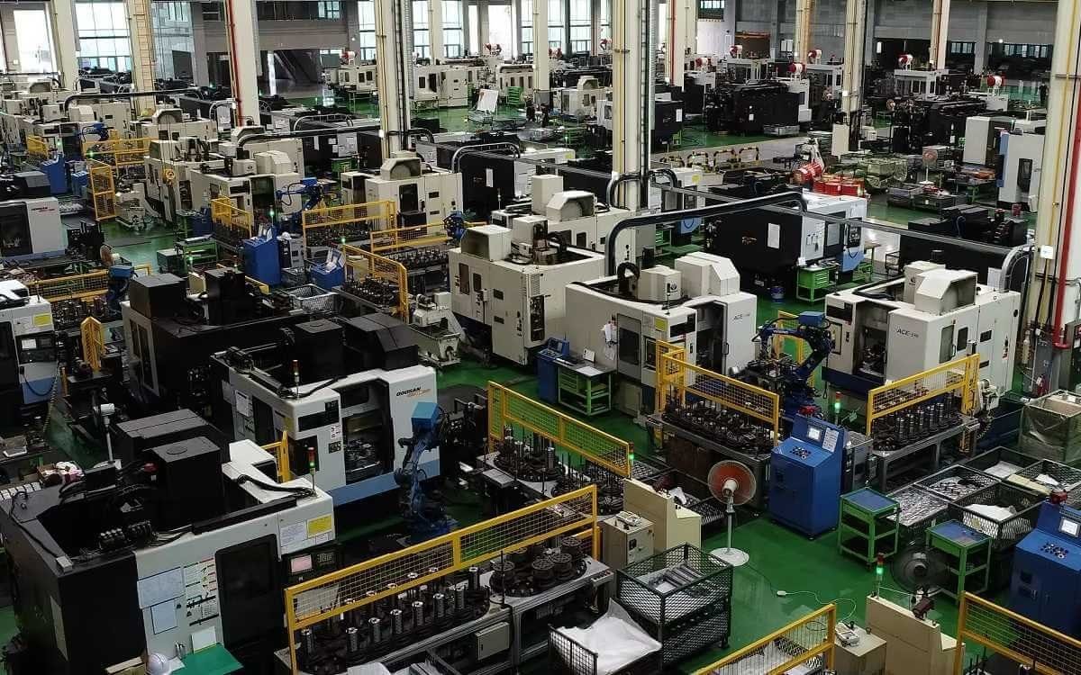
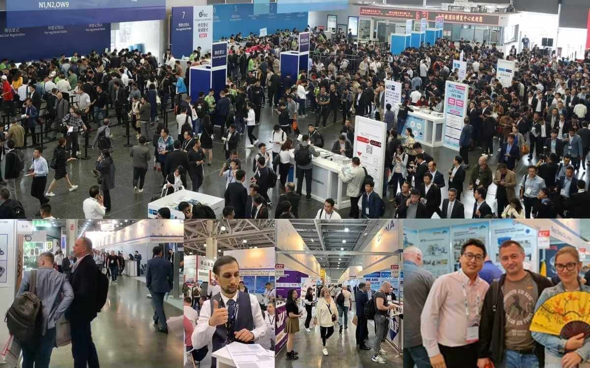
Company Profile

Frequently Asked Questions
1.What ls our Main Products?
1.Hydraulic pump
2.Hydraulic valve
3.Hydraulic motor
4.Hydraulic cylinder
5.Hydraulic parts
2. What about the MOQ?
3.What are your advantages?
- Adhere to quality first.
- Support customization, ODM & OEM service.
- 1-year warranty and complete after-sales support.
- Safe and fast shipping worldwide.
- 24-hour online service for your inquiries.
4.Are you a manufacturer? What’s your delivery time?
Yes, we are a manufacturer with our own factory.
Common models are in stock, and orders are usually shipped within 1–3 days.
5.Which payment methods are accepted?
We accept T/T, L/C, PayPal, VISA, Western Union, Apple Pay, Google Pay, Afterpay (Clearpay), Klarna, and Trade Assurance.
For full orders: 30% deposit, balance before shipment.
For small/sample orders: full payment in advance.
6.How will you deliver my goods?
We offer flexible shipping options: DHL, UPS, FedEx, TNT, EMS, as well as air or sea freight.
All deliveries ensure door-to-door fast and safe service.
7.How do you inspect and guarantee your products?
All products are tested before shipment to ensure perfect working condition.
We offer a 12-month warranty — if a product fails due to quality issues, we provide free spare parts or repair support.
8.What about after-sales service?
If you encounter any problem during use, please contact your sales manager or our support team at any time.
We will respond quickly and help solve the issue efficiently.
9.What are your main applications?
- Hydraulic systems
- Agricultural machinery
- Construction machinery
- Automobile industry
- Local distributors and maintenance centers
10.Can I get a discount for bulk orders?
Yes. We offer competitive wholesale prices and try our best to give benefits to long-term partners.
Shoot Us An Email
Professional Manufacturer