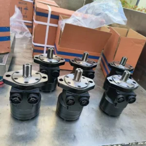
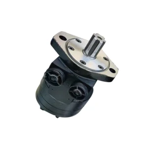
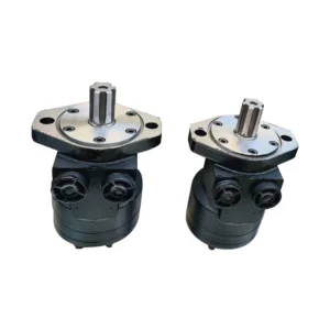
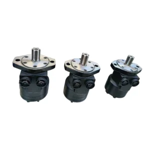
Product Overview
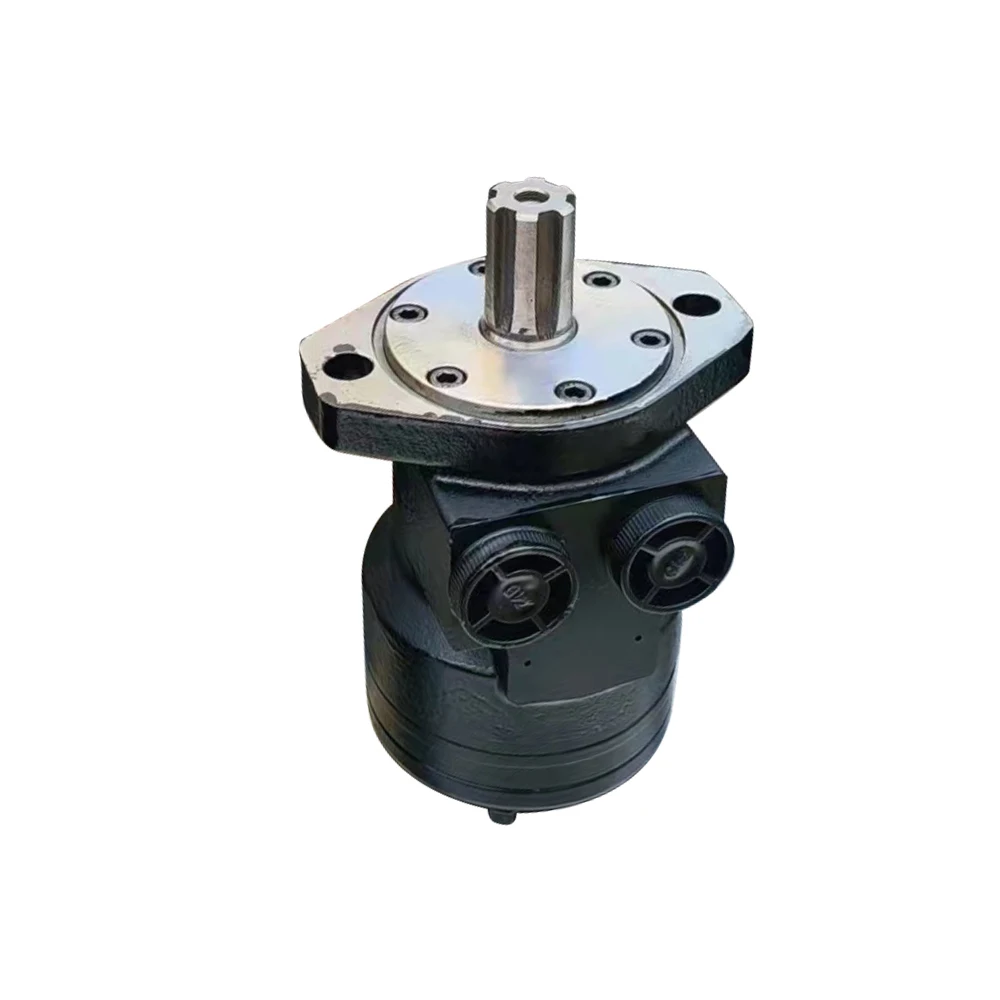
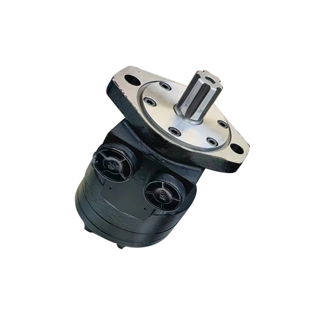
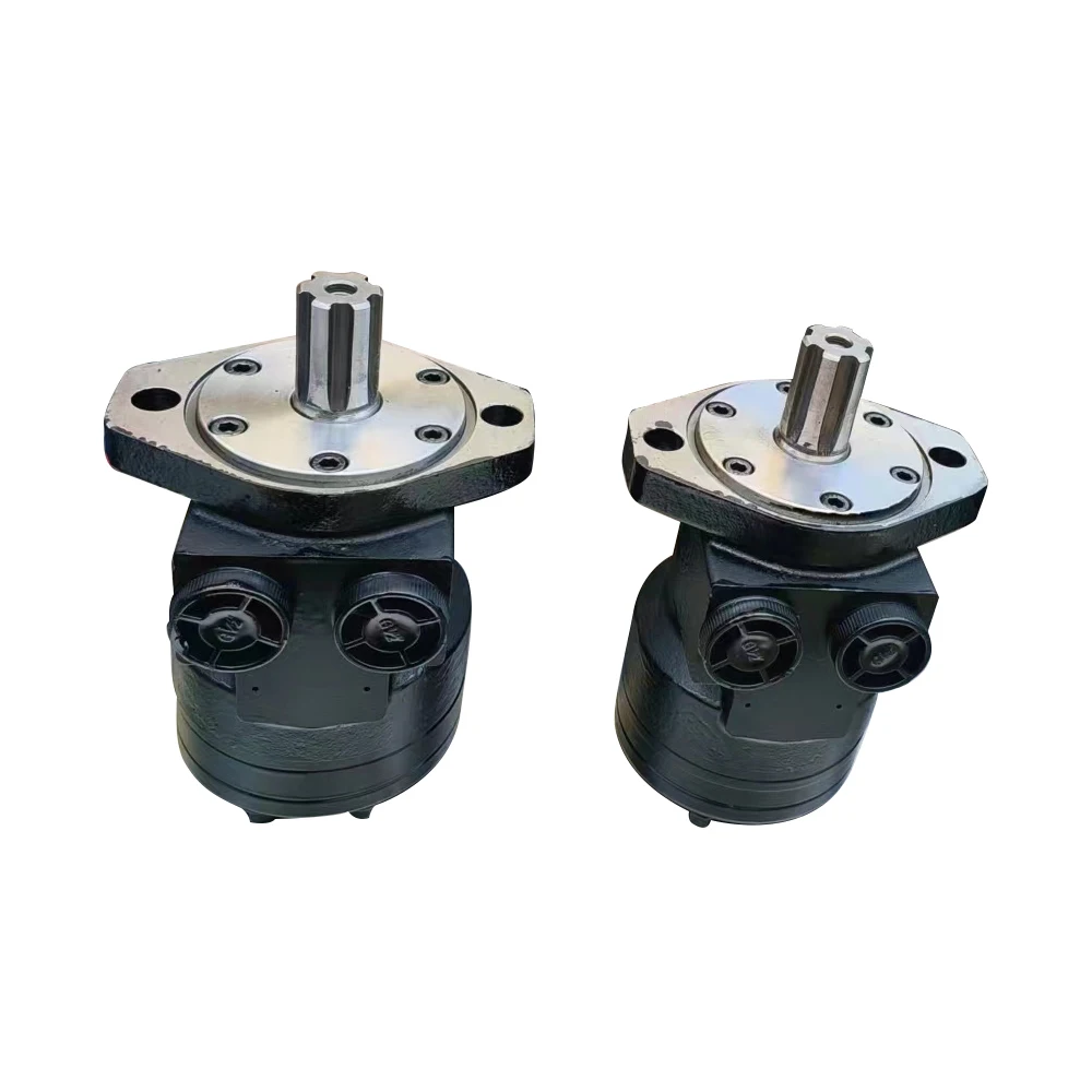
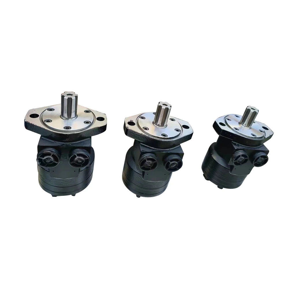
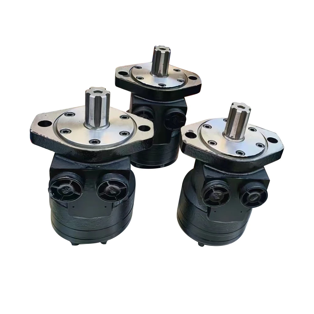
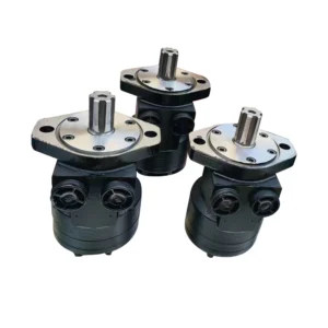
The 111A/112A Series is Parker’s Nichols™ 110A Series of medium-duty low-speed, high-torque (LSHT) orbital hydraulic motors. The series features a pressure-loaded power element design in which hydraulic pressure continuously biases the distribution element against the rotor face, creating a self-sealing effect for high volumetric efficiency that is wear-compensated and remains constant throughout the motor’s service life. The core technology highlight is a one-piece solid fixed-axis shaft that eliminates the torque link used in conventional orbital motors, enabling full stationary spline contact between shaft and rotor and significantly reducing spline contact stresses for superior resistance to rapid reversals.
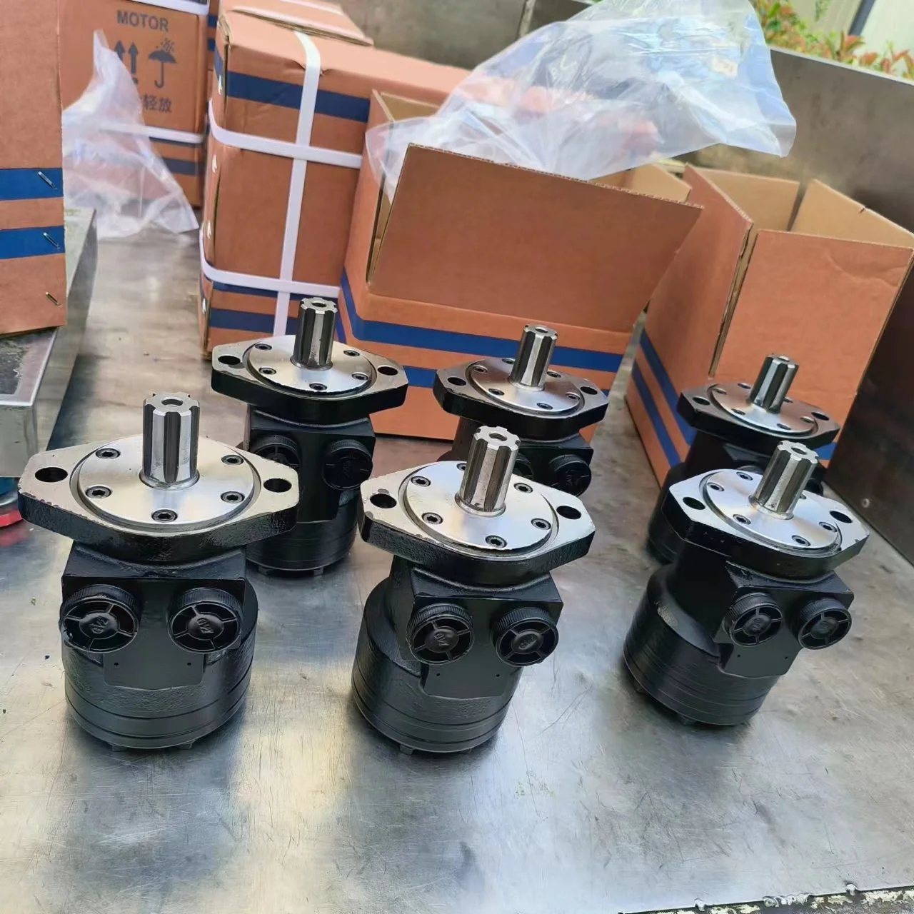
Models 111A-106-AS-0, 112A-054-A-T, 111A-129-AS-1, and 111A-129-AT-0 are 100% drop-in replacements for original Parker Nichols 110A series motors, matching mounting flanges, shaft specifications, and port configurations exactly. The shaft can be extended through the rear cover for mounting parking brakes, auxiliary drive functions, or encoders for speed readout or closed-loop control. Every unit undergoes 100% simulated load testing before shipment.
Technical Specifications
General Specifications
Brand: Parker Nichols™
Series: 110A / 111A / 112A Series
Control Type: Orbital power element, pressure-loaded distribution, wear-compensated design
Mounting Flange: SAE A 2-bolt flange, pilot Ø82.5 mm
Port Size: G 1/2 BSPP (side ported)
Rotation: Bi-directional
Housing Material: Cast Iron
Recommended Viscosity: 37–73 cSt
Oil Cleanliness: ISO 18/13
111A-106-AS-0
Displacement Code: 106
Geometric Displacement: 174 cm³/rev (10.6 in³/rev)
Max Continuous Pressure: 155 bar
Max Intermittent Pressure: 210 bar (3500 psi)
Max Continuous Speed: 654 rpm
Max Continuous Torque: 380 N·m
Max Intermittent Torque: 595 N·m
Shaft Type: Ø25.4 mm (1 inch) 6B spline shaft
Mounting: SAE A 2-bolt flange
Weight: Approx. 8.4 kg
112A-054-A-T
Displacement Code: 054
Geometric Displacement: 89 cm³/rev (5.4 in³/rev)
Max Continuous Pressure: 172 bar
Max Intermittent Pressure: 210 bar (3500 psi)
Max Continuous Speed: 942 rpm
Max Continuous Torque: 199 N·m
Max Intermittent Torque: 340 N·m
Shaft Type: Ø25.4 mm (1 inch) keyed shaft
Mounting: SAE A 2-bolt flange
Weight: Approx. 7.4 kg
111A-129-AS-1
Displacement Code: 129
Geometric Displacement: 211 cm³/rev (12.9 in³/rev)
Max Continuous Pressure: 155 bar
Max Intermittent Pressure: 210 bar (3500 psi)
Max Continuous Speed: 537 rpm
Max Continuous Torque: 458 N·m
Max Intermittent Torque: 595 N·m
Shaft Type: Ø25.4 mm (1 inch) 6B spline shaft
Mounting: SAE A 2-bolt flange
Weight: Approx. 8.7 kg
111A-129-AT-0
Displacement Code: 129
Geometric Displacement: 211 cm³/rev (12.9 in³/rev)
Max Continuous Pressure: 155 bar
Max Intermittent Pressure: 210 bar (3500 psi)
Max Continuous Speed: 537 rpm
Max Continuous Torque: 458 N·m
Max Intermittent Torque: 595 N·m
Shaft Type: Ø25.4 mm (1 inch) keyed shaft, thru-shaft design
Mounting: SAE A 2-bolt flange
Weight: Approx. 8.7 kg
Key Technical Advantages
1. Pressure-Loaded Power Element with Wear Compensation
The 110A Series power element is pressure-loaded against internal leakage for high volumetric efficiency. The wear-compensated design ensures that volumetric efficiency will not degrade with use — even as the motor approaches the end of its service life, output remains consistent. This characteristic is critically valuable for industrial applications requiring long-term stable performance.
2. One-Piece Solid Fixed-Axis Design with Low Stress
The series uses Parker’s exclusive one-piece solid fixed-axis shaft, eliminating the torque link used in conventional orbital motors. Full stationary spline contact between shaft and rotor minimizes spline contact stresses for exceptionally long life and the ability to withstand rapid reversals.
3. High Power Density in a Compact Package
The Nichols™ 110A Series is the most compact LSHT hydraulic motor in its class, delivering up to 7200 lb-in (approx. 813 N·m) of intermittent torque within a body length of only 6.6 inches. For example, the 111A-129 weighs only approximately 8.7 kg, making it ideal for installations with limited space.
4. Thru-Shaft Design for Brake and Encoder Integration
The output shaft can extend through the rear cover for mounting parking brakes, auxiliary drive functions, or speed encoders. This thru-shaft design provides exceptional flexibility for system integration, enabling braking, auxiliary drive, or closed-loop speed control without additional transmission interfaces.
5. 100% Simulated Load Testing
Every 111A/112A Series motor is validated on a 100% simulated load test bench before shipment. Testing protocols cover continuous operation at rated pressure, cyclic intermittent pressure loading, peak torque output, and internal leakage measurement, ensuring delivered performance matches published specifications.
Application Areas
Material Handling: Conveyor drives, winches, scissor lifts
Agricultural Machinery: Mini skid steer attachments, augers, sprayers
Forestry Equipment: Wood chippers, timber conveying equipment
Municipal Equipment: Salt and sand spreaders, road sweepers
Oil & Gas: Blender trucks, pipe spinners
Industrial Equipment: Industrial servo drives, factory automation equipment
Expert Maintenance Tips
Pre-Installation Checklist: Verify system oil cleanliness meets ISO 18/13. Use a return filter rated at 10 μm or finer. Ensure the SAE A 2-bolt flange pilot Ø82.5 mm fits flush against the mounting surface. Tighten bolts in a diagonal sequence. Confirm proper fit between the Ø25.4 mm shaft and coupling.
Thru-Shaft Application Notes: When using the thru-shaft function for brake or encoder mounting, verify the rear cover thru-shaft seal integrity and confirm that the radial and axial loads of the attached device are within the shaft end allowable limits. The maximum dynamic side load must not exceed 1450 lb (approx. 6,440 N).
Break-In Procedure: Before full-load operation, run new or overhauled motors at no more than 30% of continuous ratings for at least 30 minutes. This allows the power element and distribution face to achieve optimal mating surfaces.
Fluid Management: Use 68# anti-wear hydraulic oil with working viscosity maintained at 37–73 cSt. Normal operating oil temperature should be 20–60°C. Monitor oil cleanliness regularly; replace hydraulic fluid and clean filters immediately when contamination exceeds ISO 19/16.
Long-Term Storage: For storage exceeding 3 months, fill the motor interior with clean hydraulic oil and plug all ports to prevent internal corrosion. Before recommissioning, manually rotate the shaft to confirm free movement without binding.