
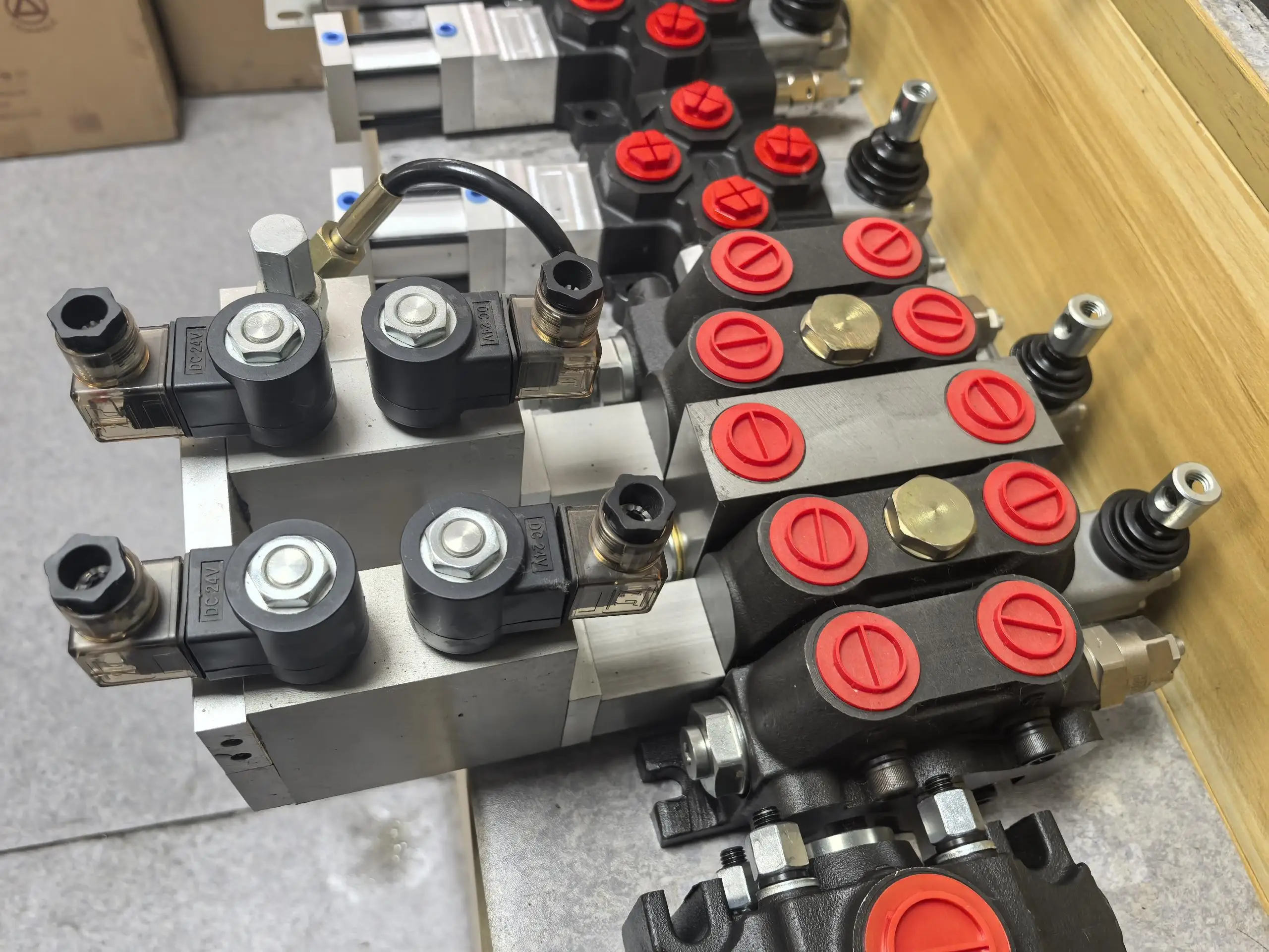

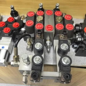

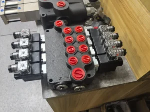


1P80 2P80 3P80 4P80 5P80 6P80 Manually Hydraulic Monoblock Control Valve 2P40 1P80 P120 P240 Solenoid Directional Control Valve
I. Technical Parameters
Core performance parameters
– Valve type: Single-actuator multi-way directional control valve, normally closed design, spring return + manual lever operation, three-position four-way O-type function, suitable for medium and low pressure hydraulic systems, achieving single-actuator direction switching and start-stop control.- Pressure and flow parameters: Rated working pressure 20 MPa, maximum allowable pressure 25 MPa (short-term ≤10 seconds); Rated flow rate: 80 L/min, maximum flow rate: 100 L/min (when pressure difference ≤0.6 MPa). Manual operating force ≤50 N, valve core stroke 10 mm.
– Sealing and life parameters: Median leakage ≤1 mL/min (at rated pressure); The reciprocating operation life is no less than 8,000 hours, and the reciprocating cycle times of the valve core are no less than 500,000 times. The ambient temperature adaptation range is from -20℃ to 85℃.
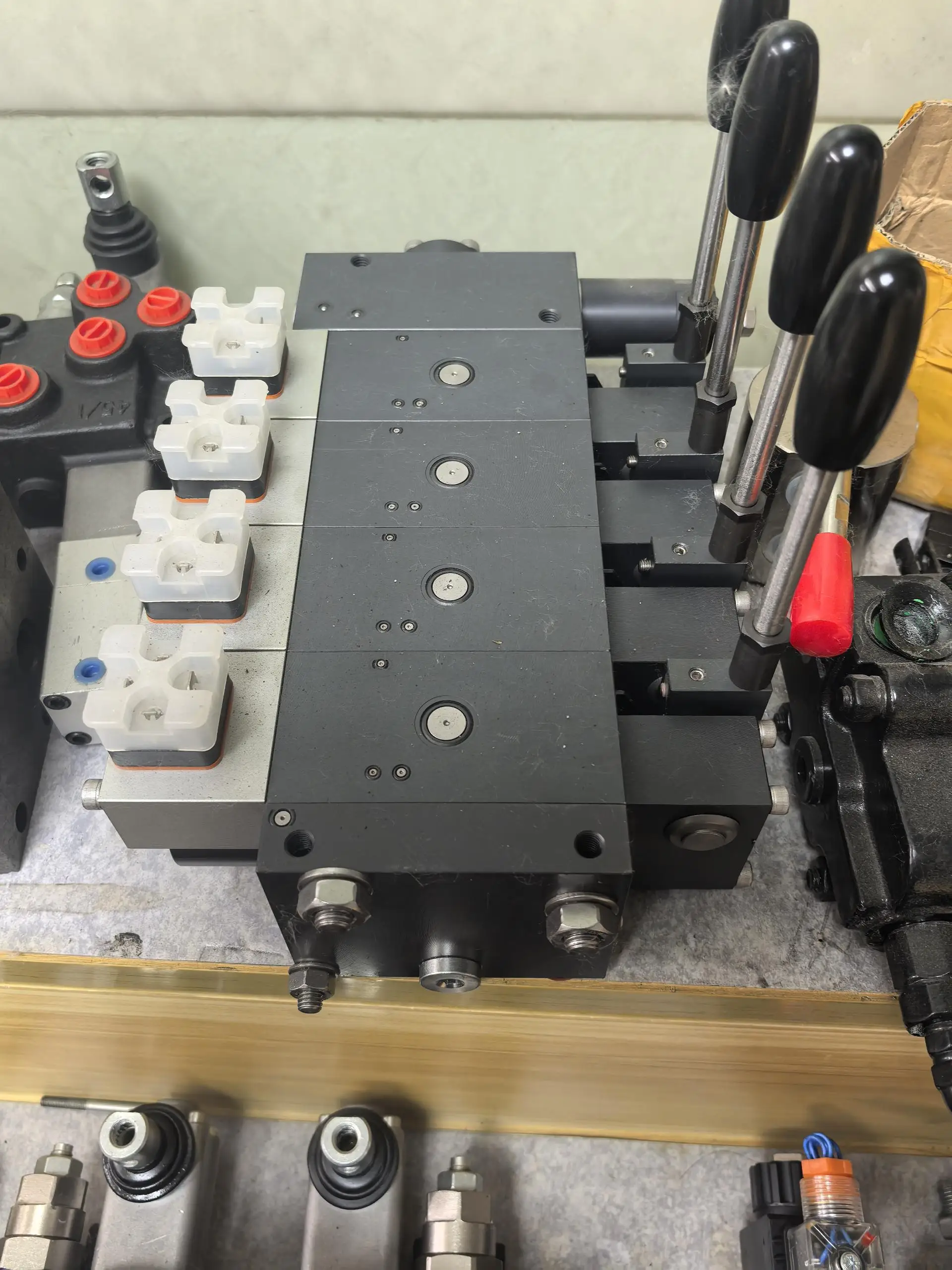
2. Structure and connection parameters
– Structural type: Spool valve type single connection structure, composed of main valve core, operating lever, reset spring, valve sleeve and sealing assembly; The valve core is equipped with a precise flow control slot, and the middle position adopts an O-shaped machine to achieve pressure holding. It integrates a one-way throttling function and can adjust the speed of the actuator.
– Core material: The main valve core is made of alloy structural steel (surface quenched treatment, hardness HRC55-58); The valve body is made of gray cast iron HT250 (hardness HB180-220). The sealing part is a combination of oil-resistant nitrile rubber and polytetrafluoroethylene (temperature resistance ≤100℃). The reset spring is made of spring steel 65Mn (with a fatigue life of ≥1 million times).
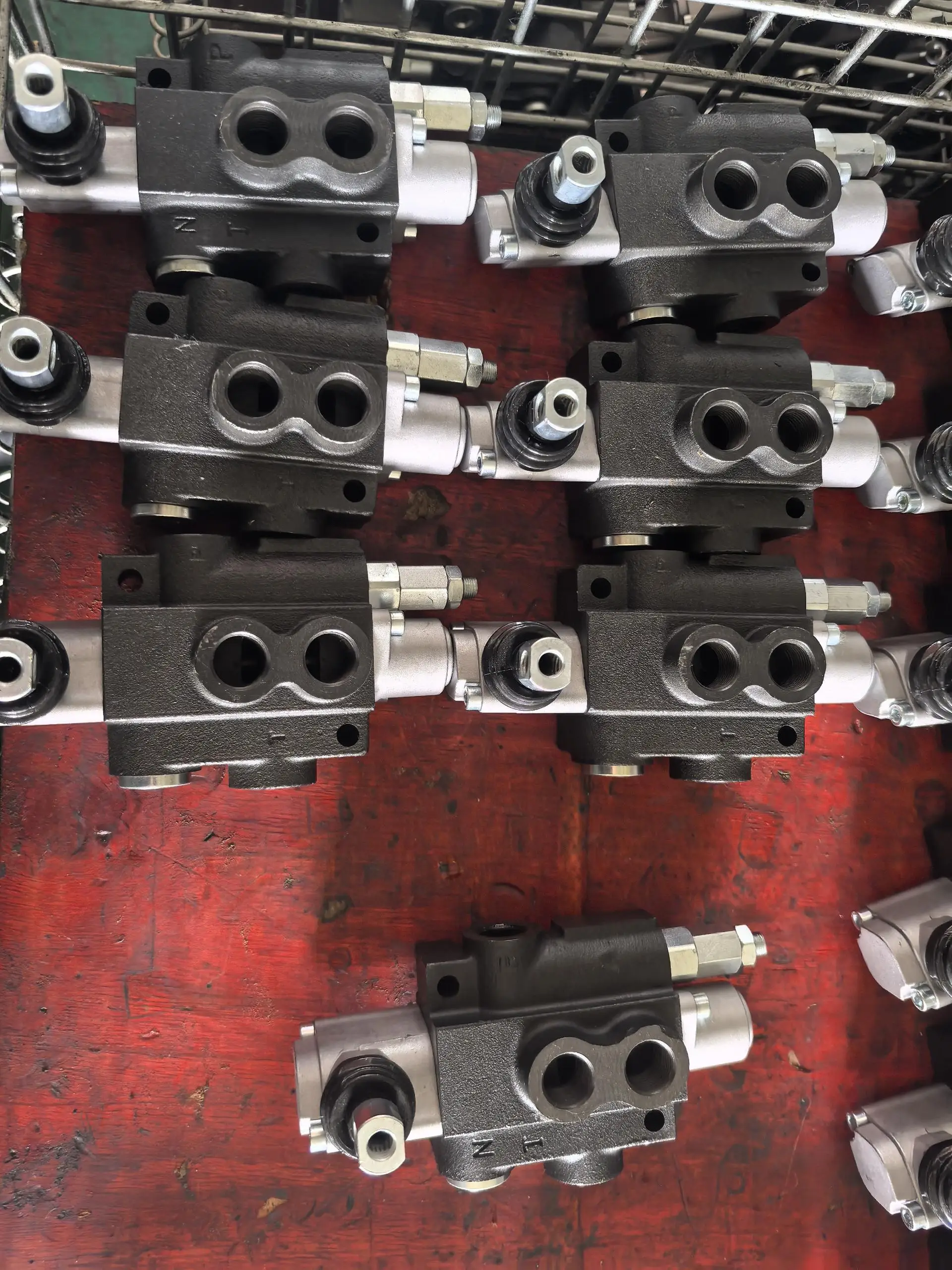
– Connection specification: The oil port connection is threaded (the P oil inlet and T oil return ports are G1.25″, and the A/B working oil port is G1″). The installation method is flange installation (bolt center distance 120× 80mm). The overall weight is approximately 6.5 kg, and the external dimensions (length × width × height) ≈380×220×180 mm.
3. Medium and Environmental requirements
– Medium requirements: Compatible with L-HM 32/46 anti-wear hydraulic oil, moisture content ≤0.03%, allowable medium viscosity 10-300 mm²/s; It is strictly prohibited to use inferior oil containing solid particles (particle size > 15 μm) or corrosive substances.
– Environmental parameters: The cleanliness of the oil should reach ISO 4406 16/13 grade, and a 15 μm filter should be placed in front of the oil suction port. The relative humidity of the working environment is ≤95%, with a protection grade of IP65. It is suitable for outdoor and workshop scenarios with a lot of dust and mild water exposure.
Ii. Working Principle
This valve is a single-clutch manual control directional control valve. The core is controlled by the hydraulic circuit through the mechanism of “manual lever driving the valve core displacement – changing the on-off relationship of the oil port – spring return and mid-position pressure holding”. The specific process is as follows:
1. Median pressure-holding state (when no operation)
When there is no manual operation, the main valve core is in the neutral position under the balanced force of the left and right reset springs. The O-type valve can keep the oil inlet P, return oil port T and working oil ports A/B all in a closed state. The actuator stops moving and maintains its original position, achieving neutral pressure holding. At this point, the system pressure is relieved through the relief valve to prevent the valve components from being subjected to long-term high-pressure impact.
2. Reversing working state (when operated manually)
When the operating lever is pushed forward, the driving force of the lever overcomes the force of the left reset spring, pushing the main valve core to move to the right, connecting the oil inlet P with the working oil port A and the working oil port B with the return oil port T. High-pressure oil enters the rodless cavity of the actuator, pushing the actuator to move forward. When the lever is pulled backward, the valve core moves to the left, achieving the connection between P and B, A and T, and the actuator moves in the opposite direction. The displacement of the valve core can be fine-tuned through the lever operation amplitude, and in combination with the flow control slot, the speed of the actuator can be steplessly adjusted.
3. Reset process
After releasing the operating lever, the elastic force of the reset spring pushes the valve core back to the center position, and all oil ports return to the closed state. The actuator stops moving and maintains pressure. If the system pressure exceeds 25 MPa, the accompanying relief valve will automatically open to unload, protecting the valve core and pipelines from overpressure damage.
Iii. Product Features and Advantages
Manual control is precise and reliable: The operating force is ≤ 50N, the lever stroke linearly corresponds to the displacement of the valve core, the speed regulation accuracy is ≤5%, and the control accuracy is 30% higher than that of ordinary manual valves. The O-type median can maintain a pressure fluctuation of no more than 0.8 MPa, making it suitable for scenarios that require precise positioning (such as the lifting of hydraulic platforms).
– Simple structure and convenient maintenance: The single-stage slide valve structure has no complex electronic components, and the number of parts is reduced by 70% compared with electro-hydraulic valves. The valve core and valve sleeve adopt clearance sealing. After wear, they can be replaced separately, and the maintenance cost is reduced by 60% compared with proportional valves. The average time for fault repair is ≤30 minutes.
– Excellent anti-pollution ability: The valve core clearance is ≥ 0.03mm, and the oil cleanliness requirement is only ISO 4406 16/13 grade, which can withstand slight impurity contamination. A 15 μm ordinary filter can meet the requirements and is suitable for dusty scenarios such as agriculture and construction machinery. Its failure rate is 50% lower than that of precision valves.
– Strong adaptability and economy: Standardized flange and oil port connection, which can directly replace products of the same specification but different brands. The single-actuator design is suitable for single-actuator systems, and the cost is 40% lower than that of double-actuator valves. With an 8,000-hour long service life design, the annual operation and maintenance cost under rated working conditions is only one third of that of electro-hydraulic valves.
Iv. Usage Functions and Purposes
1. Core usage functions
– Single actuator reversing: The forward and reverse movements of the actuator (hydraulic cylinder, motor) are switched through manual lever operation, replacing the combination of “manual stop valve + reversing valve”, simplifying the system structure and adapting to single-action scenarios such as loader lifting and hydraulic clamp opening and closing.
– Stepless speed regulation: The displacement of the valve core is controlled by the operating amplitude of the lever, and the flow rate changes linearly with the displacement, achieving stepless regulation of the actuator speed from 0 to the rated value. For example, the lifting speed regulation of a hydraulic lift does not require an additional throttle valve.
– Median pressure holding and start-stop: The O-type median machine can precisely stop the actuator, with a pressure holding time of ≥10 minutes and a pressure drop of ≤5%. Releasing the lever can quickly stop the machine, making it suitable for operation scenarios that require temporary parking (such as crane suspension while lifting a load).
2. Main application fields
In the field of small and medium-sized construction machinery: lifting circuits for 10-15 ton loaders, tilting mechanisms for 5-10 ton forklifts, and control of dozer plates for small excavators, suitable for outdoor light-load operations.
In the field of agricultural machinery: Suspension systems for 50-80 horsepower tractors, grain box lifting mechanisms for combine harvesters, and flipping control for agricultural machinery, all suitable for field operations.
– Industrial and special fields: Small hydraulic lifts, manual hydraulic pliers, drive of small conveying equipment in workshops, control of low-pressure cleaning equipment, suitable for intermittent operations in workshops and outdoors.
V. Applicable Machines and Scenarios
1. Adapt to the core machine
– Construction machinery: 10-15 ton loaders, 5-10 ton forklifts, and small excavators under 5 tons.
– Agricultural machinery: 50-80 horsepower tractors, medium-sized combine harvesters, agricultural machinery reversible plows.
– Industrial and special equipment: 1-3 ton hydraulic lifts, manual hydraulic demolition pliers, small workshop conveyor belts.
2. Typical application scenarios
– Loader lifting scenario: As the main valve of the 12-ton loader lifting circuit, it controls a flow rate of 80 L/min under a pressure of 20 MPa. Pulling the lever forward drives the lifting cylinder to rise, and the operation range adjusts the lifting speed (0-0.8 m/s). The neutral pressure holding ensures that the bucket remains suspended without sliding down, making it suitable for earthwork transfer operations on construction sites.
– Tractor suspension scenario: Equipped with a 60-horsepower tractor suspension system, it can control the lifting of plows, harrows and other farm tools. The manual lever operating force is ≤ 45N, allowing farmers to operate it easily. The O-shaped median function enables the height error of farm tools to stop to no more than 2 cm, making it suitable for adjusting the depth of field cultivation.
– Hydraulic lift scenario: Control the lifting and lowering of a 2-ton hydraulic lift. Adjust the lifting speed (0-0.5m /s) through the lever amplitude. The neutral pressure holding ensures that the platform subsidence when the lift stops is ≤ 3mm. It is suitable for the loading and unloading of goods in workshops and floor transfer scenarios.
Six. Similar models
1. Alternative models of the same series
-1P63: A small-flow model of the same structure, with a rated flow rate of 63 L/min and consistent pressure parameters. It is suitable for small equipment (such as 8-ton forklifts), and its cost is 18% lower than that of the original model.
-1P100: A high-flow model in the same series, with a rated flow rate of 100 L/min and the same pressure parameters. It is suitable for medium-sized equipment (such as 15-ton loaders), but its cost is 25% higher than that of the original model.
2. Cross-series alternative models
-1P80-O: Different median functional models (median from O-type to H-type), with P and T connected at median to achieve system unloading, suitable for scenarios that do not require pressure holding (such as conveyor belt drive), consistent performance parameters, and the cost is the same.
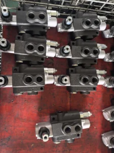
-2P80: Double valve type, integrating two 1P80 valve cores, capable of controlling two actuators, suitable for equipment requiring dual actions (such as lifting and tilting of loaders), with a cost 30% lower than that of two single valves.
-1P80-H: High-pressure enhanced model, with a rated working pressure of 25 MPa, consistent flow parameters, suitable for medium-pressure scenarios (such as 10-ton excavator bulldozers), and a cost 22% higher than the original model.
Vii. Precautions for Use
1. Medium and Selection management
Strictly select L-HM 32/46 anti-wear hydraulic oil. It is strictly prohibited to mix different grades or inferior oils. Before installing the new valve, the inner cavity of the valve body and the pipeline should be flushed with clean oil to remove the iron filings and impurities remaining during the installation process.
– Select the type based on the system pressure (≤20 MPa), flow rate (≤80 L/min), and the number of actuators. A single valve is only suitable for a single actuator. It is strictly prohibited to control multiple loads in series to avoid insufficient flow. Regularly check the cleanliness of the oil and take samples for testing every three months.
2. Installation and commissioning
When installing, be sure to confirm the oil port markings (P inlet, T return, A/B operation). It is strictly forbidden to connect them in reverse (reverse connection will cause the actuator to act in the opposite direction and even damage the sealing parts). Apply oil-resistant sealant to the flange connection and control the tightening torque at 35-40 N·m to prevent high-pressure leakage.
Before debugging, manually turn the lever 3 to 5 times to ensure that the valve core moves smoothly without any jamming. Low-pressure oil (5 MPa) is introduced to test the on-off status of the oil ports at each workstation. A leakage of ≤1 mL/min at the median is considered normal. Adjust the leverage amplitude and confirm the linear change of the actuator speed.
When installed outdoors or in a damp environment, the lever operation part should be coated with grease for rust prevention, and the surface of the valve body can be painted with anti-rust paint. The installation position should be convenient for manual operation by the operator. There should be no obstacles within the movement range of the lever to avoid operational obstruction.
3. Operation and Maintenance
During operation, check the valve body temperature (normal ≤75℃, maximum ≤85℃), leakage condition and the feel of lever operation once a week. If the temperature rises sharply by more than 15℃, the leakage is greater than 3 mL/min, or the operating force increases significantly, stop the machine immediately for inspection, with a focus on checking for oil contamination or valve core wear.
Regular maintenance every 4,000 hours: Disassemble the valve body and clean the impurities in the valve core flow control slot. Check the wear of the sealing parts (replace them when the lip is aged or damaged); Measure the fit clearance between the valve core and the valve sleeve (replace the valve core when it is greater than 0.05mm), reassemble and test the sealing performance.
It is strictly prohibited to disassemble the valve body when the system is under pressure (as it may cause oil to spray and injure people). It is strictly prohibited to strike the lever or valve core with hard objects (as it may cause deformation and jamming of the valve core). When not in use for a long time, the lever should be placed in the middle position to prevent the spring from being fatigued due to long-term force.
4. Storage protection
When stored for a long time, seal all oil ports with special plugs, inject a small amount of anti-rust oil into the valve body, and apply lithium-based grease to the moving parts of the lever. Store in a dry warehouse at 0-45℃ with a humidity of no more than 60%, avoiding direct sunlight, heavy object compression and corrosive gas erosion.
Before putting it into use after being idle for more than 12 months, thoroughly clean the inner cavity of the valve body and replace the sealing parts. Manually turn the lever to confirm there is no jamming. Then, introduce low-pressure oil to test the on-off and leakage conditions of each workstation. Only after meeting the standards can it be connected to the system for use.