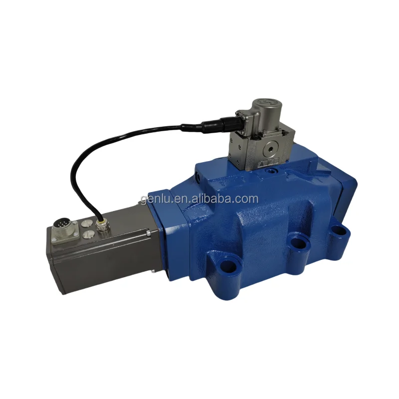
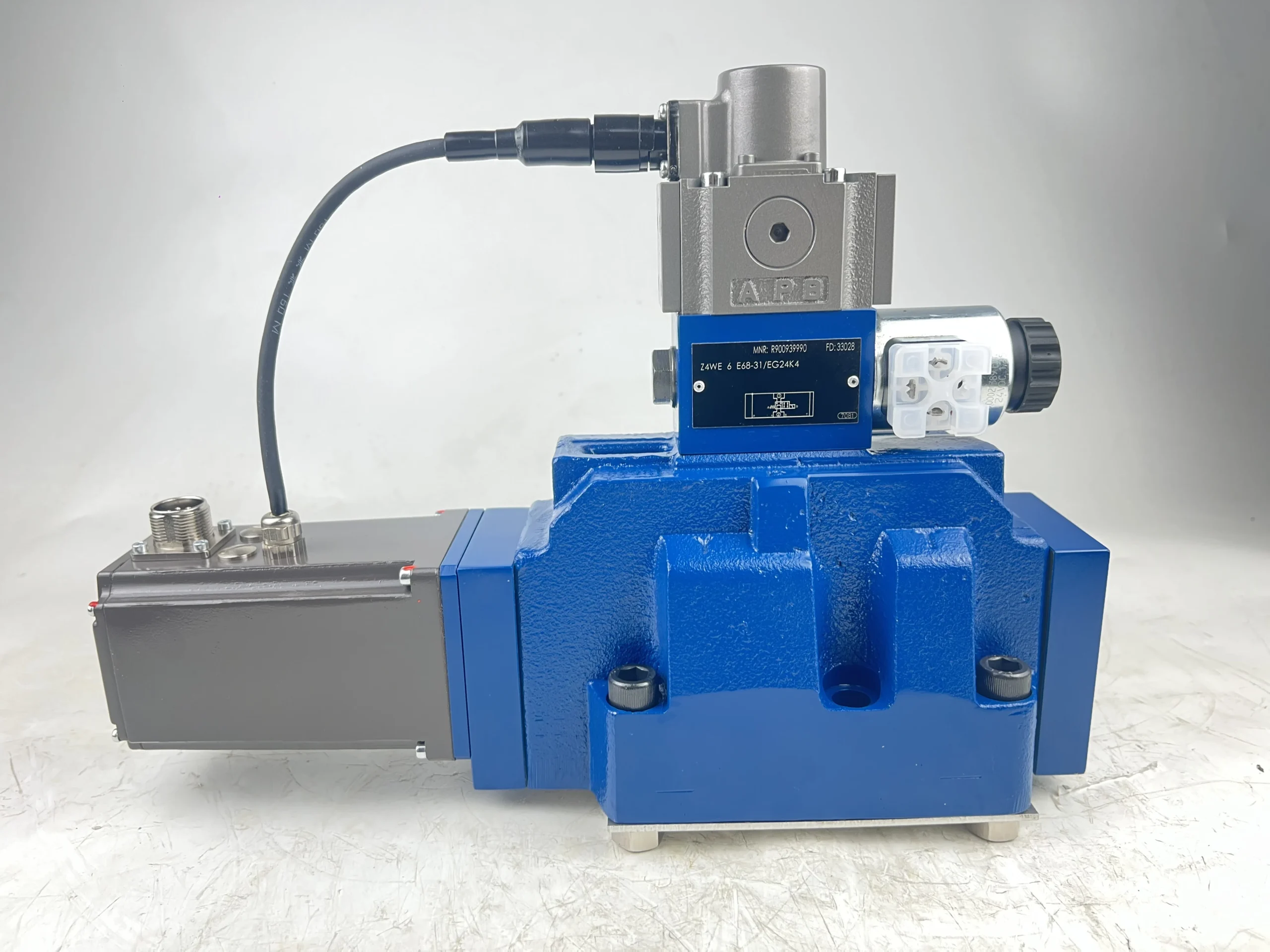
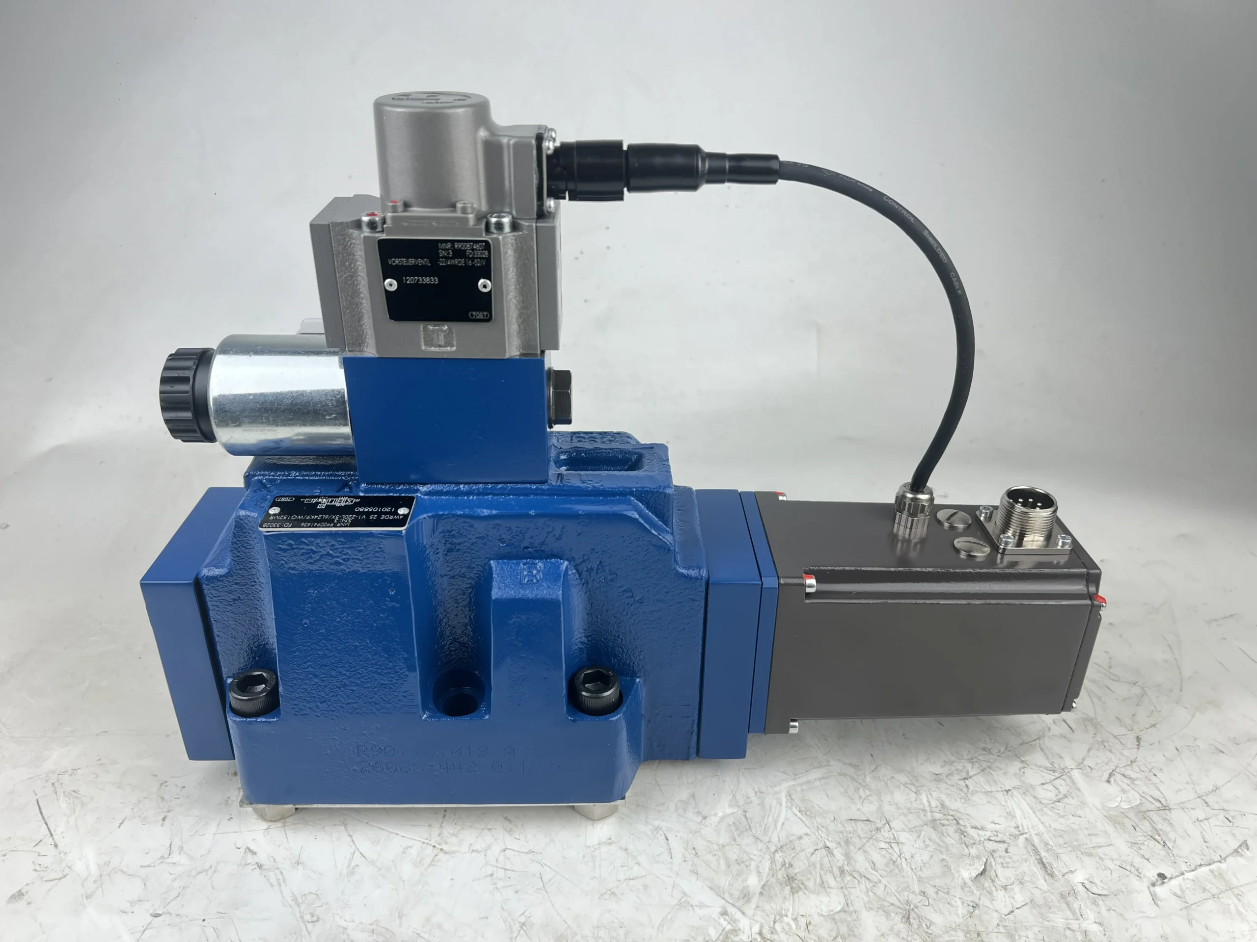


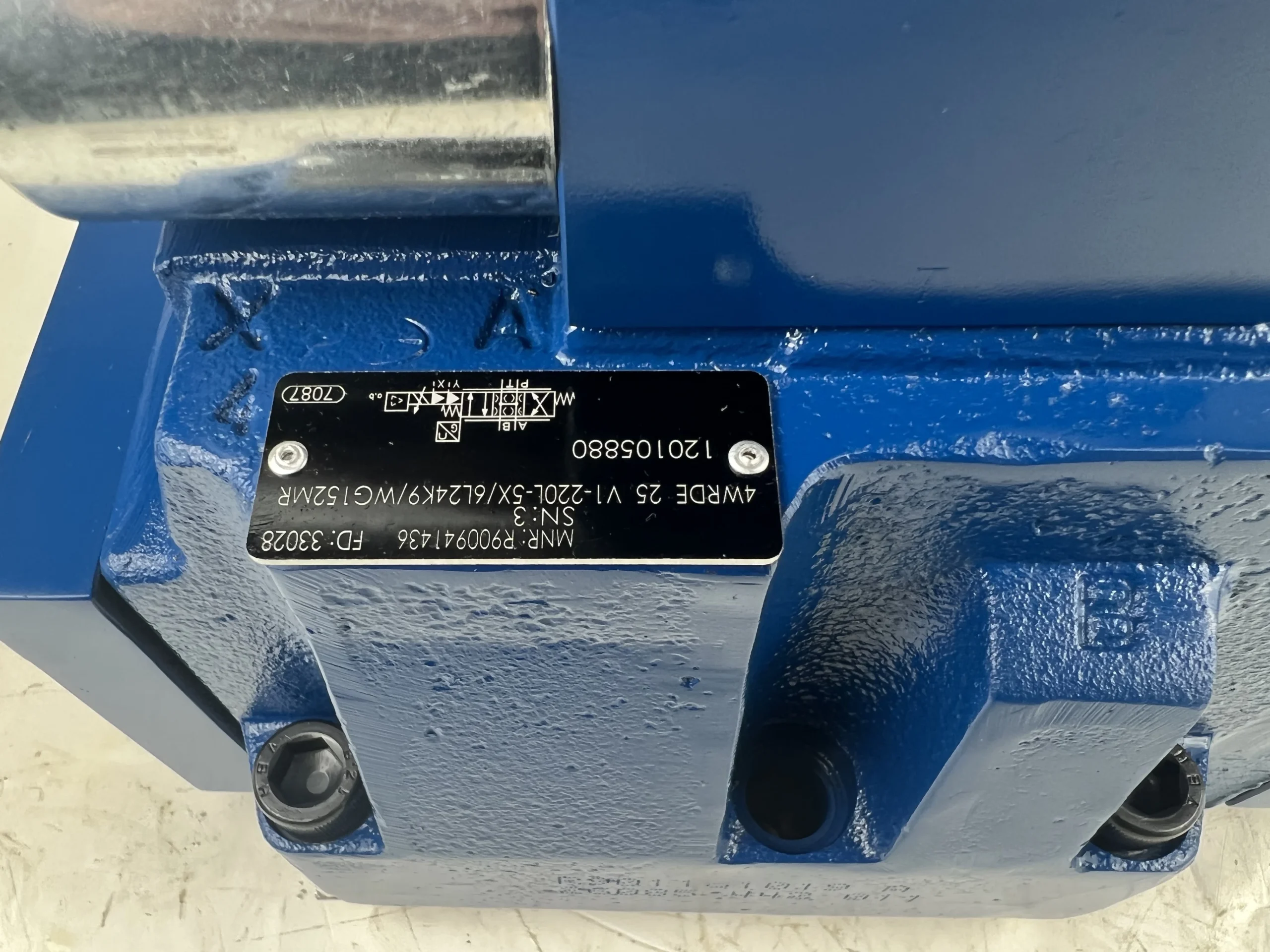


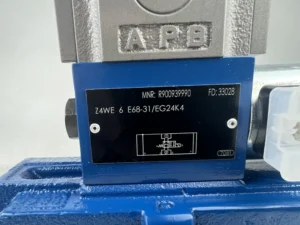

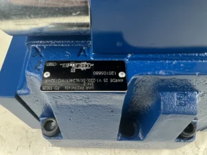
4WRDE 4WRKE 4WRLE 4WRZE Hydraulic Valve 10 16 25 27 32 Series 4WRDE 25 V1-220L-5X/6L24K9WG152MR Hydraulic Directional Valve
I. Technical Parameters
Core performance parameters
– Valve type: Direct-acting electro-hydraulic proportional directional valve with valve core position feedback closed-loop control, suitable for the coordinated regulation of direction and flow in high-pressure and high-flow hydraulic systems.
– Pressure rating: Rated working pressure 31.5 MPa, continuous operating pressure ≤31.5 MPa; The instantaneous peak pressure is 35 MPa (lasting for ≤3 seconds). The allowable back pressure at the oil return port is ≤2.5 MPa.
– Flow parameters: Rated flow rate 220L /min (corresponding to the model marked “220L”), flow regulation range 10-220 L/min; Pressure drop loss ≤0.8 MPa (at rated flow), flow control accuracy ±2%.
– Control parameters: The proportional control signal supports 4-20 mA DC current or 0-10 V DC voltage, with an input impedance of 180±30 Ω. The working voltage is DC 24V, and the power consumption is ≤ 20W. The response time of the valve core is ≤30 ms.
2. Structure and connection parameters
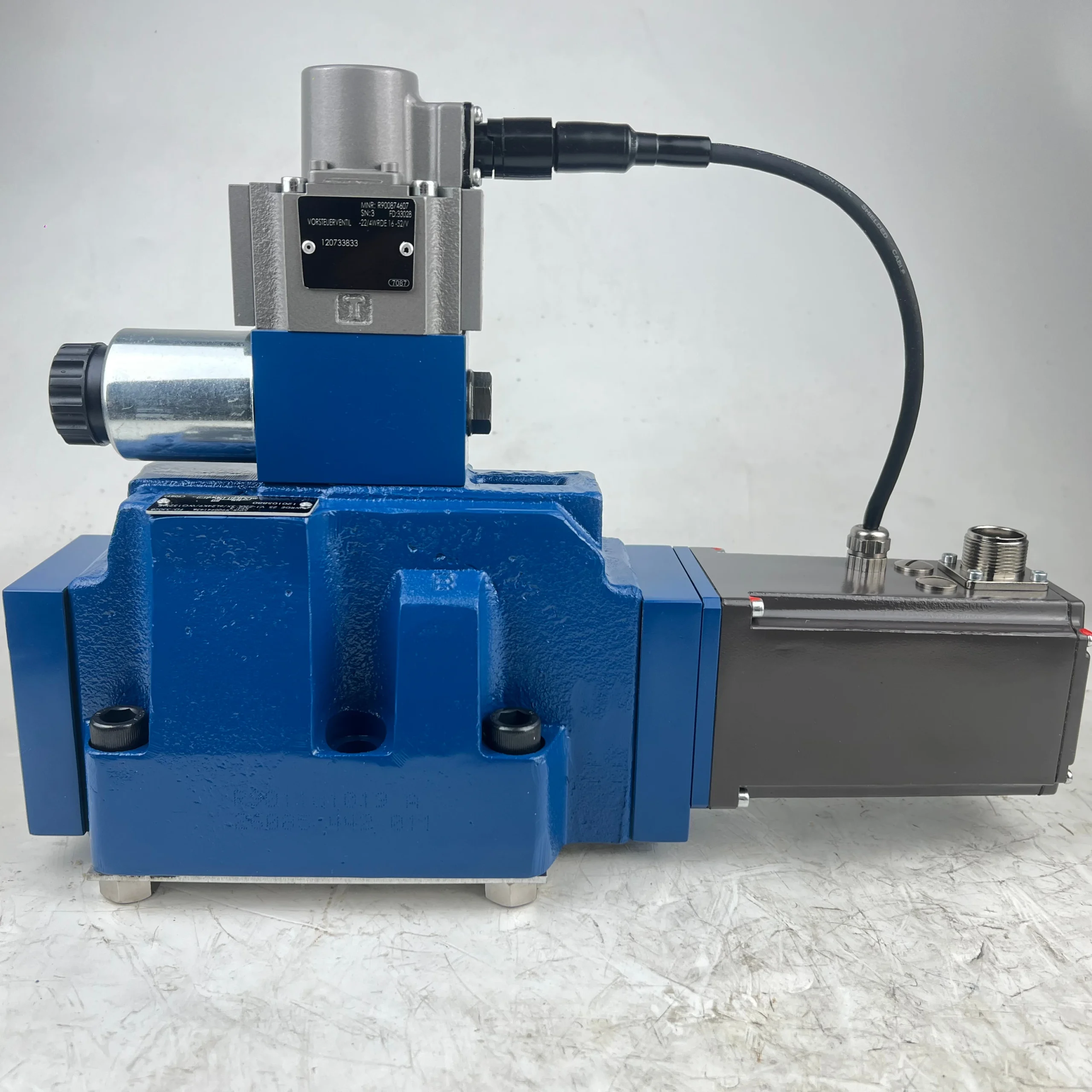
– Structural type: Horizontal installation, spool valve core structure, integrated proportional electromagnet, position sensor and manual emergency operating lever, built-in pressure compensation valve.
– Core material: The valve core is made of alloy structural steel (40CrNiMoA, quenched hardness HRC55-60); The valve body is made of high-strength forged steel (35CrMo, quenched and tempered). The sealing parts are made of high-pressure resistant fluororubber (with a temperature resistance range of -20℃ to 120℃).
– Connection specifications: The diameters of the oil inlet (P port) and return oil port (T port) are Φ 50mm, and the diameter of the working oil port (A/B port) is Φ 40mm. All are metric threads (M60×2/M50×2). The installation holes are compatible with the ISO 7005-1 standard, and the electrical interface is a waterproof aviation plug.
3. Medium and Environmental requirements
– Medium requirements: L-HM 46 anti-wear hydraulic oil is recommended. For low-temperature environments (below -20℃), L-HV 46 hydraulic oil should be selected. The kinematic viscosity of the oil is 15-400 mm²/s, and the moisture content is ≤0.1%.
– Cleanliness standard: The oil cleanliness must reach ISO 4406 16/13 grade. The system must be equipped with a 5 μm fine filter and a 100 μm coarse filter in front of the oil suction port.
– Environmental parameters: Operating environment temperature -20℃ to 80℃, relative humidity ≤95% (no condensation); With a protection grade of IP65, it is suitable for dust, oil stains and mild vibration conditions of construction machinery and industrial equipment.Ii. Working Principle
This valve is a direct-acting electro-hydraulic proportional directional valve. Its core achieves precise regulation of the oil direction and flow rate through a closed-loop control mechanism of “proportional electromagnet drive + valve core position feedback + pressure compensation”. The specific process is as follows:
1. Basic reversing and flow regulation
When A 4-20mA (or 0-10V) control signal is input, the proportional electromagnet generates A linear thrust to drive the valve core to move axially: when the valve core moves towards the A port side, the oil inlet (P) is connected to the working oil port (A), and the working oil port (B) is connected to the return oil port (T). The hydraulic oil drives the actuator to act in one direction. When the valve core moves towards the B port side, the oil port connection relationship reverses, and the actuator operates in the opposite direction. The displacement of the valve core is linearly matched with the strength of the control signal. The greater the displacement, the larger the opening of the oil port, and the greater the flow passing through, achieving flow proportional control.
2. Closed-loop feedback and pressure compensation
– Closed-loop feedback: The position sensor built into the valve core collects displacement signals in real time and feeds them back to the controller for comparison with the set signal. If there is a deviation, the electromagnet thrust is automatically adjusted to correct the valve core position, ensuring a flow control accuracy of ±2%.
– Pressure compensation: The built-in pressure compensation valve is connected to the oil inlet and working oil port. When the system load pressure changes, the compensation valve automatically adjusts the pressure drop, keeping the corresponding relationship between the oil port opening and the flow rate stable and unaffected by load fluctuations.
3. Emergency control mechanism
When the proportional control circuit malfunctions, the valve core can be directly pushed through the manual operating lever on the side of the valve body to achieve the emergency reversing action of the actuator. The operating lever position corresponds to the three working states of “left position, middle position, and right position”, ensuring that the equipment will not completely shut down due to electrical faults.
Core performance parameters
– Valve type: Direct-acting electro-hydraulic proportional directional valve with valve core position feedback closed-loop control, suitable for the coordinated regulation of direction and flow in high-pressure and high-flow hydraulic systems.
– Pressure rating: Rated working pressure 31.5 MPa, continuous operating pressure ≤31.5 MPa; The instantaneous peak pressure is 35 MPa (lasting for ≤3 seconds). The allowable back pressure at the oil return port is ≤2.5 MPa.
– Flow parameters: Rated flow rate 220L /min (corresponding to the model marked “220L”), flow regulation range 10-220 L/min; Pressure drop loss ≤0.8 MPa (at rated flow), flow control accuracy ±2%.
– Control parameters: The proportional control signal supports 4-20 mA DC current or 0-10 V DC voltage, with an input impedance of 180±30 Ω. The working voltage is DC 24V, and the power consumption is ≤ 20W. The response time of the valve core is ≤30 ms.
2. Structure and connection parameters
– Structural type: Horizontal installation, spool valve core structure, integrated proportional electromagnet, position sensor and manual emergency operating lever, built-in pressure compensation valve.
– Core material: The valve core is made of alloy structural steel (40CrNiMoA, quenched hardness HRC55-60); The valve body is made of high-strength forged steel (35CrMo, quenched and tempered). The sealing parts are made of high-pressure resistant fluororubber (with a temperature resistance range of -20℃ to 120℃).
– Connection specifications: The diameters of the oil inlet (P port) and return oil port (T port) are Φ 50mm, and the diameter of the working oil port (A/B port) is Φ 40mm. All are metric threads (M60×2/M50×2). The installation holes are compatible with the ISO 7005-1 standard, and the electrical interface is a waterproof aviation plug.
3. Medium and Environmental requirements
– Medium requirements: L-HM 46 anti-wear hydraulic oil is recommended. For low-temperature environments (below -20℃), L-HV 46 hydraulic oil should be selected. The kinematic viscosity of the oil is 15-400 mm²/s, and the moisture content is ≤0.1%.
– Cleanliness standard: The oil cleanliness must reach ISO 4406 16/13 grade. The system must be equipped with a 5 μm fine filter and a 100 μm coarse filter in front of the oil suction port.
– Environmental parameters: Operating environment temperature -20℃ to 80℃, relative humidity ≤95% (no condensation); With a protection grade of IP65, it is suitable for dust, oil stains and mild vibration conditions of construction machinery and industrial equipment.Ii. Working Principle
This valve is a direct-acting electro-hydraulic proportional directional valve. Its core achieves precise regulation of the oil direction and flow rate through a closed-loop control mechanism of “proportional electromagnet drive + valve core position feedback + pressure compensation”. The specific process is as follows:
1. Basic reversing and flow regulation
When A 4-20mA (or 0-10V) control signal is input, the proportional electromagnet generates A linear thrust to drive the valve core to move axially: when the valve core moves towards the A port side, the oil inlet (P) is connected to the working oil port (A), and the working oil port (B) is connected to the return oil port (T). The hydraulic oil drives the actuator to act in one direction. When the valve core moves towards the B port side, the oil port connection relationship reverses, and the actuator operates in the opposite direction. The displacement of the valve core is linearly matched with the strength of the control signal. The greater the displacement, the larger the opening of the oil port, and the greater the flow passing through, achieving flow proportional control.
2. Closed-loop feedback and pressure compensation
– Closed-loop feedback: The position sensor built into the valve core collects displacement signals in real time and feeds them back to the controller for comparison with the set signal. If there is a deviation, the electromagnet thrust is automatically adjusted to correct the valve core position, ensuring a flow control accuracy of ±2%.
– Pressure compensation: The built-in pressure compensation valve is connected to the oil inlet and working oil port. When the system load pressure changes, the compensation valve automatically adjusts the pressure drop, keeping the corresponding relationship between the oil port opening and the flow rate stable and unaffected by load fluctuations.
3. Emergency control mechanism
When the proportional control circuit malfunctions, the valve core can be directly pushed through the manual operating lever on the side of the valve body to achieve the emergency reversing action of the actuator. The operating lever position corresponds to the three working states of “left position, middle position, and right position”, ensuring that the equipment will not completely shut down due to electrical faults.
Iii. Product Features and Advantages
– Precise directional flow coordination: It integrates directional reversing and flow regulation functions, eliminating the need for additional flow valves. The response time of the valve core is ≤30 ms, and the flow regulation range is steplessly adjustable from 10 to 220 L/min, making it suitable for the speed and directional coordinated control of actuators (such as the speed regulation of the lifting and lowering of the excavator boom).
– Strong adaptability to high pressure and large flow: With a rated pressure of 31.5MPa, it can be adapted to heavy-duty hydraulic systems, and a rated flow rate of 220L /min meets the rapid action requirements of large actuators (such as 30-ton excavator bucket cylinders). The pressure compensation design ensures that the flow deviation is ≤2% when the load fluctuates.
– High stability of closed-loop control: The closed-loop feedback system of position sensor + controller solves the “hysteresis” problem of ordinary proportional valves, and the linearity of control signal and flow is ≥98%. It is equipped with an overload protection module. When the current of the electromagnet is too high, it will automatically cut off the power to prevent burnout.
– Good adaptability to harsh working conditions: The valve core is made of 40CrNiMoA alloy steel and treated with nitriding, which is wear-resistant and anti-seizing. The IP65 protection grade can prevent dust and oil stains from entering the electrical interface. Fluororubber seals can maintain good sealing performance at temperatures ranging from -20℃ to 120℃.
– Easy maintenance and high compatibility: The modular design enables vulnerable parts such as proportional electromagnets and seals to be replaced separately without the need to disassemble the valve body as a whole. Standardized oil ports and installation dimensions can directly replace ordinary directional valves of the same specification or proportional valves of other brands, with low installation costs.
Iv. Usage Functions and Purposes
1. Core usage functions
– Directional flow ratio control: By synchronously regulating the direction and flow of the oil through control signals, it enables stepless speed adjustment of the actuator (such as smooth switching of the lifting speed of a loader from slow to fast), adapting to the action requirements of multiple working conditions.
– Multi-actuator compound control: A single valve can achieve coordinated actions of multiple actuators through flow distribution (such as the combined operation of excavator bucket digging and boom lifting), reducing the number of valve groups in the system and simplifying pipeline design.
– Emergency manual reversing: In case of electrical faults, emergency actions are achieved through the manual operating lever to ensure that the actuator can be safely retracted when the operation is interrupted (such as retracting the bucket when the construction machinery is shut down), reducing the losses caused by faults.
– Pressure compensation adaptive: The pressure compensation valve automatically ADAPTS to load changes. It reduces flow loss and saves energy under light load and ensures stable flow under heavy load, making it suitable for scenarios with large load fluctuations (such as load changes during material handling).
2. Main application fields
– Construction machinery: 30-ton class excavator main reversing system, 20-25 ton loader lifting and flipping system, 15-20 ton crawler crane luffing and lifting system.
– Industrial manufacturing equipment: Injection and clamping systems for 500-1000 ton injection molding machines, hydraulic systems for moving the worktable of heavy-duty machine tools, and clamping and ejection systems for large die-casting machines.
– Metallurgical and mining equipment: Propulsion and rotation systems for medium-sized mine roadheaders, downward systems for metallurgical rolling mills, and drive systems for large port loading and unloading machines.
– Automated equipment: Cluster control of hydraulic actuators for large-scale automated production lines, multi-loop flow regulation systems for hydraulic test benches.
V. Applicable Machines and Scenarios
1. Adapt to the core machine
– Construction machinery: 30-ton crawler excavators, 20-25 ton wheel loaders, 15-20 ton crawler cranes.
– Industrial equipment: 500-1000 ton injection molding machines, heavy-duty horizontal machining centers, large port handling machines.
Other equipment: Medium-sized mine tunnel boring machines, small-scale metallurgical rolling mills, large-scale automated hydraulic stations.
2. Typical application scenarios
– Main reversing control of the excavator: As the main proportional valve of the 30-ton excavator, it controls the three core actuators of the boom, boom and bucket. It regulates the speed of each action through a 4-20mA signal (for example, the bucket excavation speed is steplably adjustable from 0.1 to 0.8m /s), which is suitable for scenarios such as hard rock excavation in mines and earthwork excavation in infrastructure. When performing compound actions, the flow distribution is precise without any jamming.
Injection control of injection molding machines: For the reversing and speed regulation of the injection system of 800-ton injection molding machines, the flow rate is fully opened (220 L/min) during the injection stage to achieve rapid advancement (speed ≥0.5 m/s), and the flow rate is reduced to 20 L/min during the pressure-holding stage to stabilize the pressure. This is suitable for the molding scenarios of large plastic parts, and the molding accuracy is improved by more than 10%.
– Loader lifting control: Drive the lifting mechanism of a 25-ton loader. When the valve core is in the left position, the lifting speed increases from 0.2m /s to 1.0m /s as the signal intensifies. When the valve core is in the right position, it descends smoothly. When it is in the middle position, it is locked and positioned. It is suitable for high-frequency action scenarios such as bulk cargo handling in ports and mine transportation. The operating noise is ≤ 75dB.
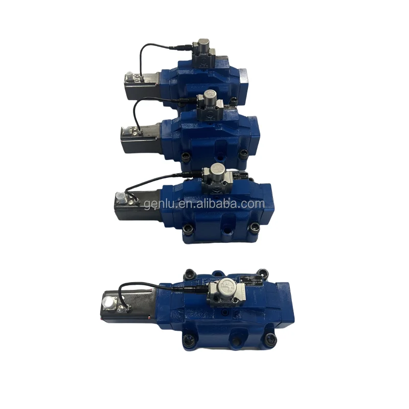
Six. Similar models
1. Alternative models of the same series
-4WRDE 25V1 -200L-5X/6L24K9WG152MR: Small flow model of the same structure, rated flow 200L /min, rated pressure 31.5MPa, fully compatible with control parameters and installation dimensions, suitable for 25-ton excavators, with a 12% lower cost.
-4WRDE 25V1 -250L-5X/6L24K – 9WG152MR: High-flow models in the same series, with a rated flow rate of 250L /min and a rated pressure of 31.5MPa. The structural materials are the same, suitable for 35-ton excavators, but the cost is 18% higher.
2. Cross-series alternative models
-4WRDE 25H1-220L-5X /6L24K9WG152MR: High-pressure upgraded model, rated pressure 35 MPa, flow rate 220L /min, valve core and valve body material upgraded (valve core surface coated with ceramic), suitable for heavy mining equipment, cost 30% higher.
-4WRDE 25V1 -220L-5X/6L110K – 9WG152MR: AC control model, operating voltage AC 110V, control signal 4-20mA, suitable for AC power supply scenarios, with similar costs.
-4WRDE 30V1 -300L-5X/6L24K – 9WG152MR: Large-sized alternative models, with a rated flow rate of 300L /min and a rated pressure of 31.5MPa, expanded installation dimensions, suitable for construction machinery of 40 tons and above, and a 45% higher cost.
Vii. Precautions for Use
1. Oil management
– Strictly select L-HM 46 or L-HV 46 anti-wear hydraulic oil. Different grades and types of oil must not be mixed. The new valve must have its oil changed after the first 300 hours of operation. Subsequently, the oil should be changed every 1,500 hours. Before changing the oil, the oil tank, pipelines and two-stage filters must be thoroughly cleaned.
– Check the oil cleanliness weekly. Replace the filter element immediately when the pressure difference of the fine filter exceeds 0.4 MPa. When the oil is found to be emulsified, discolored (brown or black), or containing metal impurities, the system should be thoroughly cleaned and new oil replaced to prevent the valve core from getting stuck or worn.
2. Installation and commissioning
When installing, it is necessary to confirm the oil port markings (P for oil inlet, T for oil return, A/B for working oil ports), and reverse connection is strictly prohibited. The installation surface of the valve body should be flat (flatness ≤ 0.05mm /m), and the bolts should be evenly tightened with a torque of 300 N·m to ensure good sealing and no leakage.
Before electrical connection, it is necessary to confirm that the power supply voltage (DC 24V) matches the control signal (4-20mA / 0-10V). The aviation plug must be firmly locked and properly treated for water resistance. Before debugging, first apply low-voltage power to check the flexibility of the proportional electromagnet’s operation, and then introduce hydraulic oil.
During debugging, first verify the normal reversing of the valve core through the manual operating lever, then connect the control signal and test the flow linearity within the 0-100% signal range. If the deviation exceeds 5%, calibration through the controller is required. It is recommended to recalibrate the correspondence between the position sensor and the flow rate every six months.
3. Operation and Maintenance
During operation, real-time monitoring of the valve body temperature (normal ≤75℃, maximum ≤85℃), system pressure and control signals is conducted. If a sudden temperature rise of ≥10℃, abnormal pressure fluctuations (fluctuation amplitude > 1 MPa), or proportional control failure is detected, the machine should be immediately shut down for inspection, with a focus on checking the cleanliness of the oil, wear of the valve core, or faults in the proportional electromagnet.
– Regular maintenance every 2000 hours: Replace seals and filter elements; Check the wear condition of the valve core (replace if radial wear is greater than 0.03mm) and the stability of the position sensor signal. Disassemble and inspect the interior of the valve body every 5,000 hours, and grind the mating surface between the valve core and the valve hole (if the mating clearance is greater than 0.04mm, repair is required).
When the proportional control is not in use for a long time, it is necessary to test the action of the electromagnet once a month to prevent the core from rusting and getting stuck. After manual operation, the operating lever needs to be reset to the center position to prevent the valve core from being permanently offset for a long time, which may cause permanent deformation of the sealing parts.
4. Storage protection
When stored for a long time, all oil ports should be sealed with special plastic plugs. Anti-rust oil (80% of the valve body volume) should be injected into the valve body, and anti-rust grease should be applied to the surface of the proportional electromagnet. Store in a dry and well-ventilated place (temperature 5-35℃, humidity ≤60%), avoiding direct sunlight and severe vibration.
Before being put into use after being idle for more than 6 months, drain the anti-rust oil and flush the valve body twice with L-HM 46 hydraulic oil. Test the performance of the proportional electromagnet and position sensor with low voltage. After installation, gradually increase the pressure to 50%, 75%, and 100% of the rated value. Run each stage for 15 minutes to confirm normal operation before putting it into use.