

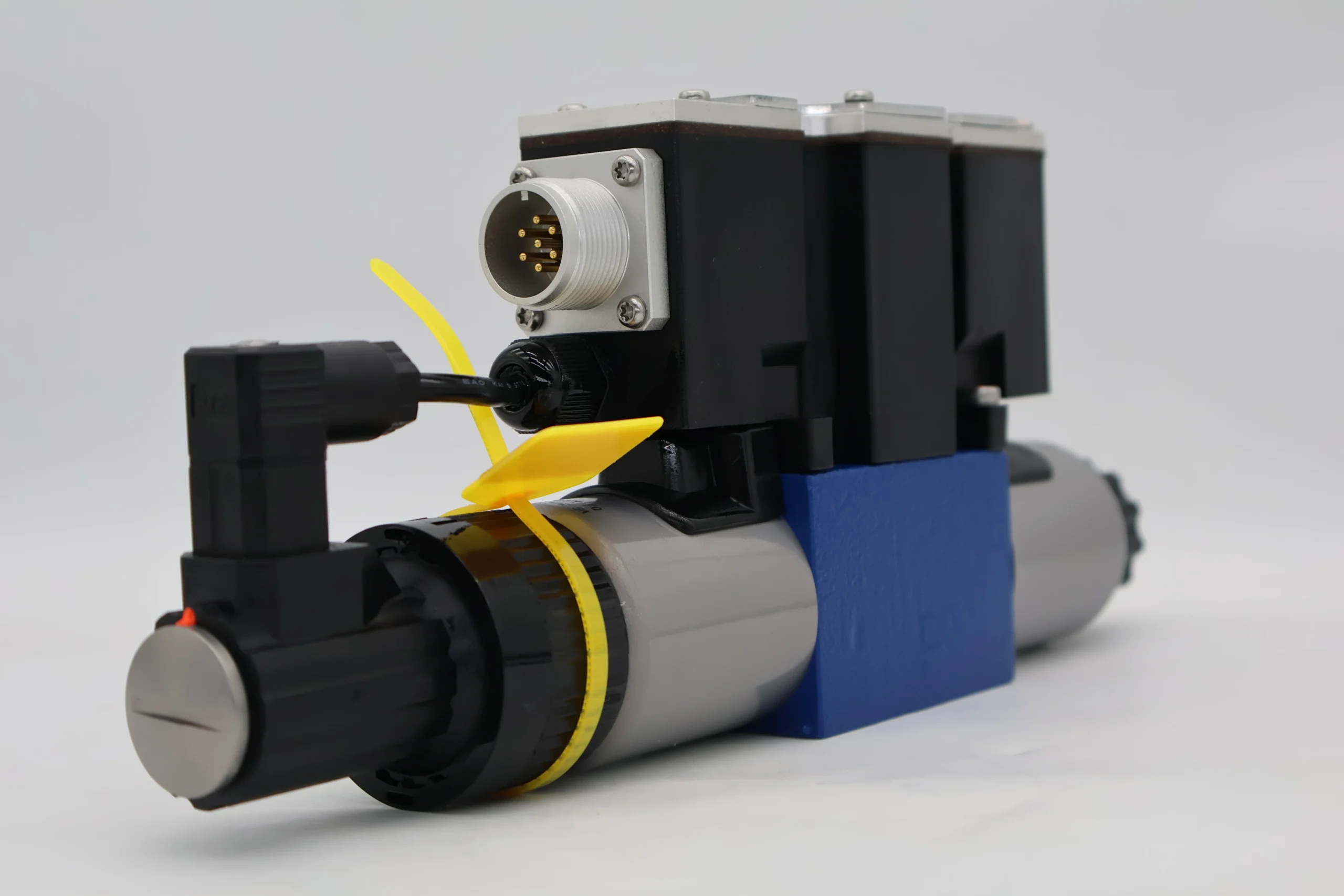
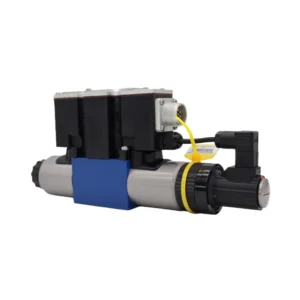


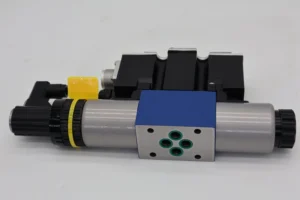

Hydraulic Solenoid Valve 4WREE 4WREE6 4WREE10 Series 4WREE6E16-23/G24K31A1V-655 Proportional Directional Hydraulic Control Valve
I. Technical Parameters
Core performance parameters
– Valve type: Electro-hydraulic proportional directional flow valve, four-position four-way structure, spring centering reset, pilot-operated proportional electromagnetic control + manual emergency regulation, suitable for medium and high-pressure hydraulic systems, achieving stepless flow regulation and direction switching.
– Pressure and flow parameters: Rated working pressure 31.5 MPa, maximum allowable pressure 35 MPa (short-term ≤10 seconds); Rated flow rate: 16 L/min (at a pressure difference of 1 MPa), maximum adjustable flow rate: 20 L/min. Pilot control voltage: DC24V (rated current: 1.2A), proportional control accuracy: ≤1%.
– Response and sealing parameters: Direction switching response time ≤50 ms, flow regulation response time ≤30 ms; The median leakage is ≤0.5 mL/min (at rated pressure). The working cycle life is ≥1 million times (under rated conditions).
– Operating characteristics: Continuous working oil temperature ≤85℃, working medium viscosity 15-400 mm²/s; The proportional electromagnet has a protection grade of IP65 and an ambient temperature range of -20℃ to 80℃.
2. Structure and connection parameters
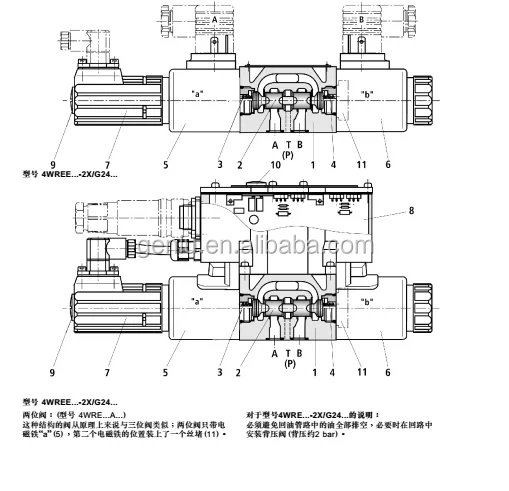
– Structural type: Spool valve structure, composed of main valve core, proportional electromagnet, reset spring, pressure compensator and manual adjustment rod; The main valve core is equipped with a flow control slot and an internal pressure compensator to ensure that the flow is not affected by fluctuations in load pressure. The median H-type function is adopted to achieve system unloading.
– Core material: The main valve core is made of alloy structural steel (surface nitriding treatment, hardness HRC58-62); The valve sleeve is made of high-strength alloy cast iron (hardness HB220-250). The sealing part is a high-pressure resistant fluororubber combination (temperature resistance ≤110℃). The armature of the proportional electromagnet is made of pure iron (magnetic permeability ≥1.5×10⁻³ H/m).
– Connection specification: The oil port connection is threaded (P oil inlet port, T oil return port, and A/B working oil port are all G3/8″). The installation method is flange installation (bolt center distance 80×60 mm). The overall weight is approximately 1.8 kg, and the valve core stroke is 6 mm.
3. Medium and Environmental requirements
– Medium requirements: Compatible with L-HM 32/46 anti-wear hydraulic oil, moisture content ≤0.02%, strictly prohibited to contain solid particles (particle size > 5 μm) or corrosive media; The contamination degree of the oil should reach ISO 4406 14/11 grade.
– Environmental parameters: Operating environment temperature -20℃ to 80℃, relative humidity ≤95% (short-term condensation is allowed); The proportional electromagnet has a protection grade of IP65 and is suitable for dusty scenarios such as industrial machine tools, construction machinery, and injection molding equipment.Ii. Working Principle
This valve is an electro-hydraulic proportional directional flow valve. Its core achieves precise control of the hydraulic system through the mechanism of “electrical signal – proportional force conversion – valve core displacement – flow direction regulation”. The specific process is as follows:
1. Median reset state (when no power is on
When there is no control signal, the proportional electromagnet is de-energized, and the main valve core is in the neutral position under the pre-tightening force of the left and right reset springs. The H-type machine can connect the oil inlet P with the oil return T, close the working oil ports A/B, and unload the system. At this point, the valve core can be forcibly pushed by manually adjusting the lever to achieve emergency direction switching.
2. Direction switching and flow regulation (when powered on)
When the proportional electromagnet on the left is energized, the electromagnetic force drives the pilot valve core to move. The control oil acts on the left end of the main valve core, pushing it to move to the right, thus achieving the P→A and B→T paths, and the actuator moves forward. When the electromagnet on the right side is energized, the main valve core moves to the left, achieving the P→B and A→T paths, and the actuator moves in the opposite direction. Meanwhile, the intensity of the input electrical signal is directly proportional to the thrust of the electromagnet, which drives the displacement of the valve core to change linearly. The flow control slot on the main valve core enables the passing flow to be adjusted steplessly with the displacement. The pressure compensator balances the load pressure in real time to ensure the flow is stable and not affected by pressure fluctuations.
3. Stop and protect the process
After the electromagnet is de-energized, the main valve core returns to the neutral position under the action of the reset spring, and the system resumes unloading. When the system pressure exceeds 35 MPa, the built-in relief valve in the valve body automatically unloads to protect the valve core and pipelines from overpressure damage. The proportional electromagnet is equipped with built-in overheat protection. It will automatically cut off power when the current exceeds 1.5A to prevent burnout.
Core performance parameters
– Valve type: Electro-hydraulic proportional directional flow valve, four-position four-way structure, spring centering reset, pilot-operated proportional electromagnetic control + manual emergency regulation, suitable for medium and high-pressure hydraulic systems, achieving stepless flow regulation and direction switching.
– Pressure and flow parameters: Rated working pressure 31.5 MPa, maximum allowable pressure 35 MPa (short-term ≤10 seconds); Rated flow rate: 16 L/min (at a pressure difference of 1 MPa), maximum adjustable flow rate: 20 L/min. Pilot control voltage: DC24V (rated current: 1.2A), proportional control accuracy: ≤1%.
– Response and sealing parameters: Direction switching response time ≤50 ms, flow regulation response time ≤30 ms; The median leakage is ≤0.5 mL/min (at rated pressure). The working cycle life is ≥1 million times (under rated conditions).
– Operating characteristics: Continuous working oil temperature ≤85℃, working medium viscosity 15-400 mm²/s; The proportional electromagnet has a protection grade of IP65 and an ambient temperature range of -20℃ to 80℃.
2. Structure and connection parameters
– Structural type: Spool valve structure, composed of main valve core, proportional electromagnet, reset spring, pressure compensator and manual adjustment rod; The main valve core is equipped with a flow control slot and an internal pressure compensator to ensure that the flow is not affected by fluctuations in load pressure. The median H-type function is adopted to achieve system unloading.
– Core material: The main valve core is made of alloy structural steel (surface nitriding treatment, hardness HRC58-62); The valve sleeve is made of high-strength alloy cast iron (hardness HB220-250). The sealing part is a high-pressure resistant fluororubber combination (temperature resistance ≤110℃). The armature of the proportional electromagnet is made of pure iron (magnetic permeability ≥1.5×10⁻³ H/m).
– Connection specification: The oil port connection is threaded (P oil inlet port, T oil return port, and A/B working oil port are all G3/8″). The installation method is flange installation (bolt center distance 80×60 mm). The overall weight is approximately 1.8 kg, and the valve core stroke is 6 mm.
3. Medium and Environmental requirements
– Medium requirements: Compatible with L-HM 32/46 anti-wear hydraulic oil, moisture content ≤0.02%, strictly prohibited to contain solid particles (particle size > 5 μm) or corrosive media; The contamination degree of the oil should reach ISO 4406 14/11 grade.
– Environmental parameters: Operating environment temperature -20℃ to 80℃, relative humidity ≤95% (short-term condensation is allowed); The proportional electromagnet has a protection grade of IP65 and is suitable for dusty scenarios such as industrial machine tools, construction machinery, and injection molding equipment.Ii. Working Principle
This valve is an electro-hydraulic proportional directional flow valve. Its core achieves precise control of the hydraulic system through the mechanism of “electrical signal – proportional force conversion – valve core displacement – flow direction regulation”. The specific process is as follows:
1. Median reset state (when no power is on
When there is no control signal, the proportional electromagnet is de-energized, and the main valve core is in the neutral position under the pre-tightening force of the left and right reset springs. The H-type machine can connect the oil inlet P with the oil return T, close the working oil ports A/B, and unload the system. At this point, the valve core can be forcibly pushed by manually adjusting the lever to achieve emergency direction switching.
2. Direction switching and flow regulation (when powered on)
When the proportional electromagnet on the left is energized, the electromagnetic force drives the pilot valve core to move. The control oil acts on the left end of the main valve core, pushing it to move to the right, thus achieving the P→A and B→T paths, and the actuator moves forward. When the electromagnet on the right side is energized, the main valve core moves to the left, achieving the P→B and A→T paths, and the actuator moves in the opposite direction. Meanwhile, the intensity of the input electrical signal is directly proportional to the thrust of the electromagnet, which drives the displacement of the valve core to change linearly. The flow control slot on the main valve core enables the passing flow to be adjusted steplessly with the displacement. The pressure compensator balances the load pressure in real time to ensure the flow is stable and not affected by pressure fluctuations.
3. Stop and protect the process
After the electromagnet is de-energized, the main valve core returns to the neutral position under the action of the reset spring, and the system resumes unloading. When the system pressure exceeds 35 MPa, the built-in relief valve in the valve body automatically unloads to protect the valve core and pipelines from overpressure damage. The proportional electromagnet is equipped with built-in overheat protection. It will automatically cut off power when the current exceeds 1.5A to prevent burnout.
Iii. Product Features and Advantages
– Precise and efficient proportional control: The DC24V proportional electromagnetic control ensures a flow regulation accuracy of ≤1% and a directional switching response time of ≤ 50ms, which is 80% more accurate than that of ordinary electromagnetic directional control valves. The pressure compensator ensures that the flow rate fluctuation is ≤2% when the load pressure fluctuates by ±5 MPa, making it suitable for precise speed regulation scenarios (such as machine tool feed).
– Integration and multi-functionality: It integrates three major functions: direction switching, flow regulation, and pressure relief, replacing the combination of “direction valve + flow valve + relief valve”, reducing system components by 60%. The median H-type machine can achieve system unloading and reduce energy consumption by more than 30%.
– Stable, reliable and long service life: The valve core undergoes nitriding treatment and features a pressure compensation structure, which enhances the wear resistance by 50% compared to ordinary slide valves. The proportional electromagnet adopts a sealed design, with IP65 protection against dust and oil stains. Its working cycle life is ≥1 million times, which is twice as long as that of conventional valves.
– Easy operation and strong adaptability: Supports 0-10V analog signal control and can be directly connected to the PLC system to achieve automatic control. It is equipped with a manual emergency adjustment rod, allowing manual operation when the electromagnet malfunctions. Standardized flange connections are compatible with general hydraulic systems, and installation and replacement only take 5 minutes.
Iv. Usage Functions and Purposes
1. Core usage functions
– Precise flow regulation: The flow rate is steplessly adjusted from 0 to 20 L/min through proportional electrical signals. Combined with pressure compensators, the speed of the actuator is stabilized, making it suitable for scenarios requiring precise speed regulation, such as machine tool feed and injection molding machine injection.
– Bidirectional proportional drive: It controls the switching of electrical signals to achieve the forward and reverse movements of the actuator. The switching process is shock-free, and the flow rate changes linearly with the signal, such as the smooth control of the “grasping – releasing” action of a hydraulic manipulator.
– System unloading protection: The median H-type can unload the system, reducing standby energy consumption. The built-in relief valve provides overpressure protection to prevent the actuator from being overloaded and damaged, making it suitable for intermittent hydraulic systems.
2. Main application fields
In the field of industrial machine tools: feed axis drive for CNC lathes, worktable movement control for milling machines, and feed adjustment of grinding wheels for grinding machines, suitable for precision processing scenarios.
In the field of plastic machinery: control of injection circuits for small and medium-sized injection molding machines, adjustment of molding actions for blow molding machines, and driving of feeding for extruders, suitable for plastic molding production.
In the field of construction machinery: control of the bucket movement of small excavators, steering adjustment of hydraulic loaders, and lifting control of aerial work platforms, suitable for light-load and precise movement scenarios.
V. Applicable Machines and Scenarios
1. Adapt to the core machine
– Industrial machine tools: CNC lathes (Φ300- 500mm), vertical milling machines, surface grinding machines.
– Plastic machinery: 50-100 ton injection molding machines, small blow molding machines, single-screw extruders.
– Construction machinery: 5-10 ton small excavators, 10-15 ton hydraulic loaders, 6-12 meter aerial work platforms.
2. Typical application scenarios
– Feed scenario for CNC lathes: As a feed drive valve for the X-axis of CNC lathes, it inputs 0-10V analog signals to achieve stepless adjustment of feed speed from 0 to 5m /min. The flow regulation accuracy is ≤1%, ensuring that the roundness error of the processed parts is ≤ 0.01mm, and is suitable for precision shaft processing.
– Injection molding machine injection scenario: Equipped with an 80-ton injection molding machine injection circuit, the injection speed is linearly increased from 50 mm/s to 200 mm/s through proportional signal control, with a switching response time of 40 ms, avoiding molten material splashing, suitable for plastic shell molding production, and the qualification rate is increased by 25%.
– Aerial work platform scenario: Control the lifting loop of a 10-meter aerial work platform. Proportional adjustment ensures a smooth transition of the platform’s lifting speed from 0.1m /s to 0.5m /s. The speed fluctuation is ≤2% when the load changes, ensuring operation safety. IP65 protection is suitable for outdoor construction environments.
Six. Similar models
1. Alternative models of the same series
-4WREE6E10-23 /G24K31A1V-655: A small-flow model of the same structure, with a maximum adjustable flow rate of 10 L/min. The pressure parameters are consistent, suitable for small equipment (such as Φ300 CNC lathes), and the cost is 20% lower than that of the original model.
-4WREE6E25-23 /G24K31A1V-655: A high-flow model in the same series, with a maximum adjustable flow rate of 25 L/min and the same pressure parameters. It is suitable for medium-sized equipment (such as 100-ton injection molding machines), but the cost is 30% higher than that of the original model.
2. Cross-series alternative models
-4WREE6W16-23 /G24K31A1V-655: Median O-type functional model, with A/B/P/T fully enclosed at median, suitable for pressure-holding scenarios (such as hydraulic fixtures), consistent performance parameters, and equal cost.
-4WREE6E16-23 /G12K31A1V-655: Low-voltage control model, control voltage DC12V, suitable for vehicle-mounted low-voltage systems (such as small electric excavators), with consistent flow and pressure parameters. The cost is 15% higher than that of the original model.
-4WRE6E16-23 /G24K31A1V-655: Electromagnetic control model, eliminating proportional adjustment function, only achieving direction switching, suitable for scenarios that do not require speed regulation, with a cost 40% lower than the original model.
4WREE 6V08-23/G24K31/A1V
4WREE 10W 75-23/G24K31/A1V
4WRTE 32 E600L 4X/6EG24ETK31/A1M
4WRZE 25 W6-325-70/6EG24N9K31/A1M
R900924283 4WREE6W08-23/G24K31/F1V,
R900927356 4WREE10E75-23/G24K31/F1V,
R900246793 4WREE6W32-23/G24K31/F1V,
R900925657 4WREE6W16-23/G24K31/A1V,
R900927235 4WREE10V50-23/G24K31/A1V,
R900907440 4WREE6V16-23/G24K31/A1V,
R900911681 4WREE6V32-23/G24K31/A1V,
4WRE 6 V16-21/G24K4/V-822
4WRE 6W16-21/G24K4/V
4WRE6W16-23/G24K41V
4WREE 10 V75-23/G24K31/A1V
4WREE 10 W1-75-23/G24K31/A1V
4WREE 6 E32-23/G24K31/A1V
4WREE10E75-23/G24Z4A1V
4WREE10W1-75-23/G24K31/F1V plug
4WREE10W75-23/G24K31/F1V
4WREE6 V08 22/G24K31/A1V
4WREE6 W16-23 G24K31/ALV SN 0000003 7081
4WREE6V08-23/G24K31/A1V
4WREE6V-15-23/G24K31/A1V
4WREE6V-15-23/G24K31/F1V
4WREEM 10 E50-20/G24K34/B6V
4WRKE 10 W1-100-23/6A24ETK9/D3M
4WREE6V1-08-23/G24K31/A1V
R901161258 4WREE6E32-22/G24K31/A1V-204
R901028415 4WREE10R3-75-22/G24K31/A1V
R900617766 4WREE6WA16-22/G24K31/F1V
R900617482 4WREE6E1-16-22/G24K31/F1V
R900617269 4WREE10V75-22/G24K31/F1V
R900617253 4WREEM6E32J-22/G24K34/B6V-687
R900582331 4WRE10E16-13/24K4/M
R900576935 4WRE10E32-13/24K4/M-402
R900551280 4WRE6W1-08-13/24K4/M
R900549113 4WRE10E1-32-13/24K4/M
R900487026 4WRE6W32-13/24Z4/M
R900461236 4WRE10W1-16-13/24K4/M
R901136691 4WREQ6Q5-08-22/V5C-24PF60
R901135153 4WREE6V08-22=G24K31/F1V-876
R901135118 4WREE10W75-22/G24K31/A1V-280
R901132085 4WREQ6Q5-32-22/V4A-24PF60
R901131081 4WREQ6V08-22/V8F-24CA60
R901131077 4WREQ10V25-22/V8F-24CA60
R901130450 4WREE10W1-75-22/G24K31/A1V-660
R901130447 4WREE6E16-22/G24K31/A1V-660
R901127151 4WREE10W25-22/G24K31/A1V-280
R901126284 4WREE10E50-22/G24K31/A1V-280
R901125908 4WREF6E32-22/V-24PA1
R901125120 4WREE6V08-22/G24K31/A1V-742
R901120444 4WREE10V1-75-22/G24K31/A0V-907
R901116919 4WREE6Q5-32-22/G24K31/A1V=DE
R901113546 4WREE10Q00-22/G24K31/A1V-598=DE
R901113540 4WREE6Q00-22/G24K31/A1V-598=DE
R901113345 4WREE10Q5-50-22/G24K31/A1V=DE
R901112728 4WREE10E25-22/G24K31/A1V-280
R901109650 4WREE6V32-22/G24K31/F1V-876
R901107901 4WREE6V16-22=G24K31/F1V-876
R901104507 4WREE10W75-22/G24K31/F1V-742
R901103279 4WREQ6Q5-08-22/V4C-24CA60
R901102113 4WREQ6V16-22/V5F-24CF60
R901102112 4WREQ6Q5-16-22/V5F-24CF60
R901100120 4WREE10E75-22/G24K31/A1V-660
R901100118 4WREE10W1-50-22/G24K31/A1V-660
R901095159 4WREE6Q00-22/G24K31/A1V-598
R901091639 4WREE6V16-22/G24K31/F1V-876
R901090746 4WREEM10E1-75-22/G24K34/B6V
R901089537 4WREQ6Q5-16-22/V8C-24PA60
R901086329 4WRE10WA50-22/G24K4/V
R901085278 4WREE6V32-22/G24K31/A1V-742
R901084068 4WREEM10R3-75-22/G24K34/B6V
R901083525 4WREQ6Q5-16-22=V8C-24CF60
R901083029 4WREEM10W1-75-22/G24K34/B6V
R901081738 4WREQ6Q5-08-22/V4C-24PA60
R901080574 4WREQ6V32-22/V4C-24CA60
R901078764 4WREF6W32-22/V-24CA1
R901078404 4WREQ6Q5-32-22/VBF-24CA60
R901078403 4WREQ6Q5-16-22/VBF-24CA60
R901078402 4WREQ6Q5-08-22/VBF-24CA60
R901078399 4WREQ6Q5-08-22/V8F-24CA60
R901077950 4WREQ6Q5-16-22/V00-24CF69
R901077667 4WREQ6Q5-16-22/V00-24CA69
R901076729 4WREE6V32-22=G24K31/A1V-826
R901075515 4WRE6W32-13/24K4/M-298
R901072924 4WREQ6Q5-16-22/V8C-24CF60
R901071989 4WREE10V75-22=G24K31/A1V-826
R901071988 4WREE10V50-22=G24K31/A1V-826
R901071987 4WREE6V16-22=G24K31/A1V-826
R901071985 4WREE6V08-22=G24K31/A1V-826
R901071941 4WRE10E3-75-22/G24K4/V-660
R901068955 4WREE6V16-22/G24K31/A1V-826
R901066667 4WREE10E1-25-22/G24K31/F1V
R901066046 4WREE10Q5-50-22/G24K31/A1V
R901063517 4WREF10E3-50-22/V-24CA1
R901063172 4WREE6EB08-22/G24K31/F1V
R901063131 4WREE10WA50-22/G24K31/F1V
R901060222 4WREE10V75-22/G24K31/A1V-826
R901059709 4WREQ6Q5-32-22/V8C-24CA60
R901060996 4WREE10WA25-22/G24K31/F1V
R901057547 4WREQ10Q5-75-22/VBF-24CA60Vii. Precautions for Use
1. Medium and Selection management
Strictly select L-HM 32/46 anti-wear hydraulic oil. The cleanliness of the oil should reach ISO 4406 14/11 grade. It is strictly prohibited to contain solid particles or corrosive media. Select the type based on the system pressure (≤31.5 MPa) and flow rate (≤20 L/min). It is strictly prohibited to use beyond the parameters to avoid valve core jamming.
Before installing the new system, the pipelines should be flushed with clean oil in a circulating manner for more than 120 minutes to remove iron filings and impurities. Before installation, check the terminal blocks of the proportional electromagnet to ensure that the insulation resistance is ≥10 MΩ.
2. Installation and commissioning
When installing, confirm the oil port markings (P inlet, T return, A/B operation). It is strictly forbidden to connect them in reverse (reverse connection will cause the actuator to act in the opposite direction). Apply oil-resistant sealant to the flange connection and control the tightening torque at 25-30 N·m to prevent leakage.
Before debugging, check the control signal (0-10V analog quantity) and the supply voltage (DC24V±5%). After power-on, test the median leakage (≤0.5 mL/min), adjust the flow rate from 0 to 20 L/min, and confirm that the flow rate linearly corresponds to the signal (linearity ≤1%).
When installed outdoors or in damp environments, the proportional electromagnet needs to be equipped with a waterproof cover to ensure that the protection level remains at IP65. The valve body installation should be kept away from strong magnetic field equipment to avoid interference with the proportional electromagnetic control accuracy.
3. Operation and Maintenance
During operation, monitor the response time of the valve core, leakage volume and the temperature of the electromagnet (normal ≤60℃) every month. If the response delay exceeds 10 ms, the leakage is greater than 1 mL/min, or the electromagnet overheats, immediately stop the machine for inspection, with a focus on checking the cleanliness of the oil or the status of the proportional electromagnet coil.
– Regular maintenance every 8 months: Disassemble the valve core assembly and check the wear of the seals (replace them when the lip is damaged). Clean the impurities in the flow groove of the valve core and measure the fit clearance between the valve core and the valve sleeve (replace when > 0.015mm). Calibrate the flow-signal linearity after reassembly.
It is strictly prohibited to operate with power on without oil (as it may cause the valve core to sinter). Long-term operation under overpressure (> 35 MPa) is strictly prohibited. Before the system is shut down, the valve should be switched to the neutral position to unload the system and then the power supply should be disconnected.
4. Storage protection
When stored for a long time, the oil port should be blocked with a special plug, anti-rust oil should be applied to the surface of the valve core, and the terminal blocks of the proportional electromagnet should be sealed with insulating caps. Store in a dry warehouse at 0-45℃ with a humidity of no more than 60%, avoiding direct sunlight, heavy object compression and strong magnetic field interference.
Before being put into use after being idle for more than 12 months, thoroughly clean the valve core assembly and replace the sealing parts. Connect to low-pressure oil (5 MPa) to test the flexibility of action, power on to calibrate the proportional control accuracy, and only after meeting the standards can it be connected to the system.