
Product Overview
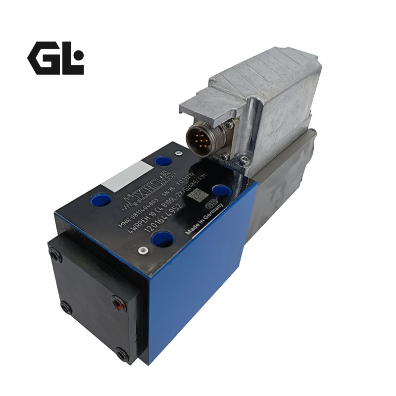
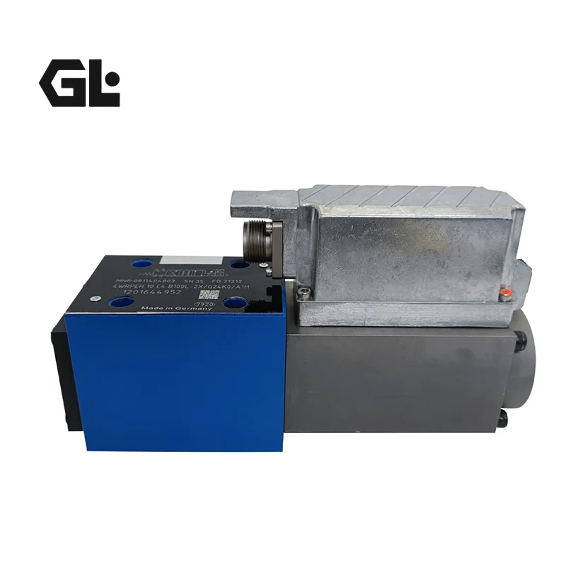
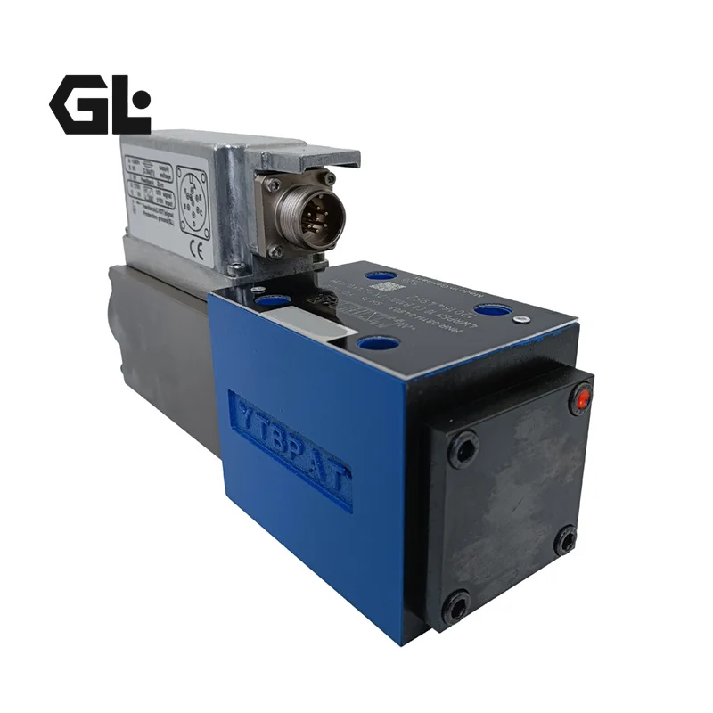
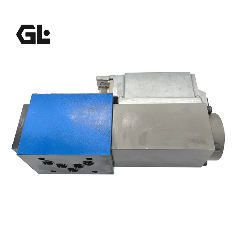
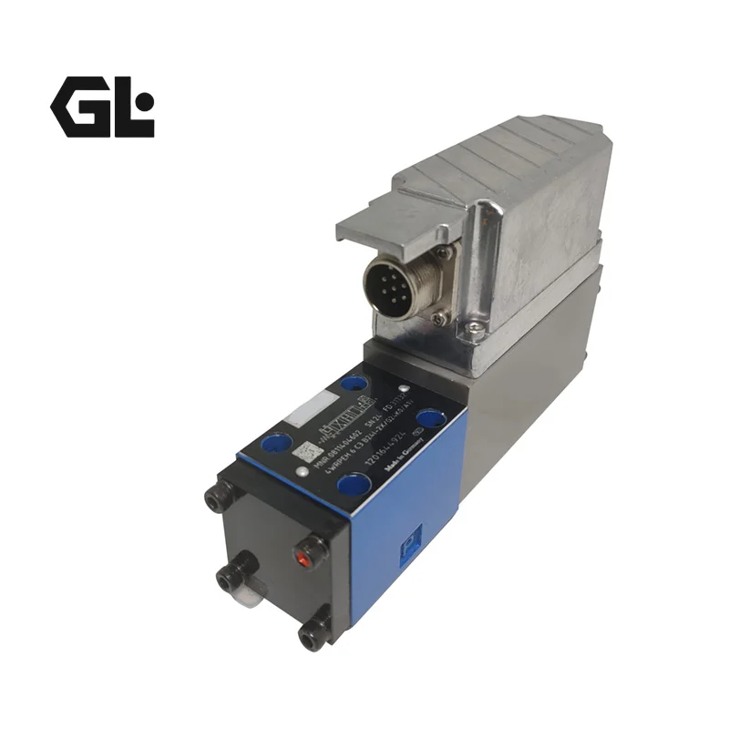
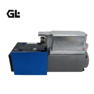
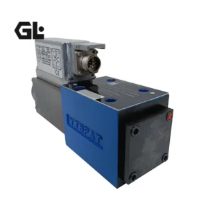
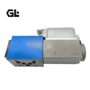
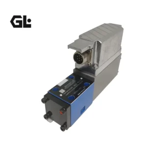
The Bosch Rexroth 4WRPEH 10 C3B100L-2X/G24K0/A1M is a high-response, direct-operated proportional directional valve with electrical position feedback and integrated on-board electronics (OBE).
Rexroth defines the 4WRPEH 10 as a servo-solenoid valve using a directly operated spool design with a steel sleeve, proportional solenoid actuation, inductive position feedback and integrated trigger electronics. The valve uses a standardized NG10 / ISO 4401-05-04-0-94 subplate mounting interface.
The two configurations supplied in your source title are:
- 4WRPEH 10 C3B100L-2X/G24K0/A1M
- 4WRPEH 10 C4B100L-2X/G24K0/A1M
The Rexroth catalog identifies them as:
- 0811404801 → 4WRPEH 10 C3B100L-2X/G24K0/A1M
- 0811404803 → 4WRPEH 10 C4B100L-2X/G24K0/A1M
The major platform characteristics are shared, but C3 and C4 represent different spool-symbol configurations. Therefore, they should not automatically be considered interchangeable only because their size, flow rating and electronics are similar. The original hydraulic symbol must be verified.
The ordering code identifies:
- 4WRP: Direct-operated proportional directional valve platform
- E: Integrated electronics
- H: Control spool/sleeve design
- 10: NG10 nominal size
- C3 / C4: Spool symbol configuration
- B: Inductive position transducer on side B
- 100: 100 L/min nominal flow
- L: Linear flow characteristic
- 2X: Component series 20 to 29
- G24: 24 V DC electronics supply
- K0: DIN 43563-AM6 connection arrangement without line socket
- A1: ±10 V command input
- M: NBR seals for mineral-oil hydraulic fluids.
A critical specification point is that 100 L/min is a nominal flow rating, defined by Rexroth at 70 bar total valve pressure difference, corresponding to 35 bar per metering notch. This is more meaningful for engineering selection than simply advertising an isolated maximum-flow figure.
Technical Specifications
4WRPEH 10 C3B100L-2X/G24K0/A1M
- Manufacturer: Bosch Rexroth
- Product Type: Direct-operated proportional directional valve with electrical position feedback and integrated electronics
- Full Type Code: 4WRPEH 10 C3B100L-2X/G24K0/A1M
- Material Number: 0811404801
- Nominal Size: NG10 / Size 10
- Spool Symbol: C3
- Nominal Flow: 100 L/min
- Flow Characteristic: Linear
- Nominal Flow Test Condition: Δp = 35 bar per metering notch
- Maximum Operating Pressure, P/A/B: 315 bar
- Maximum T-Port Pressure: 250 bar
- Actuation: Proportional solenoid with position control and OBE
- Position Feedback: LVDT inductive position transducer
- Transducer Location: Side B
- Electronics Supply: +24 V DC
- Command Input: A1, ±10 V
- Electrical Connection: K0, DIN 43563-AM6
- Seal Material: NBR
- Mounting: Subplate mounting
- Mounting Interface: NG10, ISO 4401-05-04-0-94
- Ambient Temperature: -20 to +50 °C
- Hydraulic Fluid Temperature: -20 to +70 °C
- Recommended Viscosity: 20 to 100 mm²/s
- Maximum Permitted Viscosity: 10 to 800 mm²/s
- Fluid Cleanliness: ISO 4406 Class 18/16/13
- Hysteresis: ≤0.2%
- Manufacturing Flow Tolerance: ≤10%
- 0–100% Signal Response Time: ≤25 ms
- Thermal Drift: Zero-point displacement ≤1% at ΔT = 40 °C
- Zero Adjustment: Factory-set ±1%
- Duty Cycle: 100% ED
- Protection: IP65
- Maximum Solenoid Power: 60 VA
- Permitted Supply Range: 21–40 V DC
- Low-Voltage Shutdown: Internal rapid shutdown below 18 V DC
- Weight: 7.1 kg
- Displacement: Not applicable
- Maximum Speed: Not applicable
- Peak Pressure: No separate peak-pressure rating is specified; selection should be based on the specified operating-pressure limits of 315 bar at P/A/B and 250 bar at T.
4WRPEH 10 C4B100L-2X/G24K0/A1M
- Manufacturer: Bosch Rexroth
- Product Type: Direct-operated proportional directional valve with electrical position feedback and integrated electronics
- Full Type Code: 4WRPEH 10 C4B100L-2X/G24K0/A1M
- Material Number: 0811404803
- Nominal Size: NG10 / Size 10
- Spool Symbol: C4
- Nominal Flow: 100 L/min
- Flow Characteristic: Linear
- Maximum Operating Pressure, P/A/B: 315 bar
- Maximum T-Port Pressure: 250 bar
- Actuation: Proportional solenoid with position control and OBE
- Position Feedback: LVDT inductive position transducer
- Transducer Location: Side B
- Electronics Supply: +24 V DC
- Command Input: A1, ±10 V
- Electrical Connection: K0, DIN 43563-AM6
- Seal Material: NBR
- Mounting: Subplate mounting
- Mounting Interface: NG10, ISO 4401-05-04-0-94
- Ambient Temperature: -20 to +50 °C
- Hydraulic Fluid Temperature: -20 to +70 °C
- Recommended Viscosity: 20 to 100 mm²/s
- Maximum Permitted Viscosity: 10 to 800 mm²/s
- Fluid Cleanliness: ISO 4406 Class 18/16/13
- Hysteresis: ≤0.2%
- Manufacturing Flow Tolerance: ≤10%
- 0–100% Signal Response Time: ≤25 ms
- Thermal Drift: Zero-point displacement ≤1% at ΔT = 40 °C
- Zero Adjustment: Factory-set ±1%
- Duty Cycle: 100% ED
- Protection: IP65
- Maximum Solenoid Power: 60 VA
- Permitted Supply Range: 21–40 V DC
- Weight: 7.1 kg for the 4WRPEH 10 base configuration in the Rexroth technical documentation
- Displacement: Not applicable
- Maximum Speed: Not applicable
- Peak Pressure: No separate official peak-pressure specification; maximum operating pressure is 315 bar at P/A/B and 250 bar at T.
Key Technical Advantages
1. LVDT position feedback for dynamic spool control
The defining advantage of the 4WRPEH platform is the combination of proportional solenoid actuation, LVDT position feedback and OBE electronics.
The spool position is electrically monitored, allowing the integrated electronics to control the spool according to the command signal and actual position. Rexroth states that the electronics are factory calibrated.
2. Fast response of ≤25 ms
The official technical data specify a 0–100% command-signal response time of ≤25 ms.
This is important for applications requiring rapid hydraulic acceleration and deceleration, high cycle rates and accurate dynamic flow control.
3. 100 L/min nominal flow with linear characteristic
The B100L configuration provides a 100 L/min nominal flow rate, while L represents a linear flow characteristic.
The Rexroth flow rating is defined under a specified pressure-drop condition, making the data suitable for hydraulic-system sizing rather than simply serving as a marketing maximum.
4. 315 bar high-pressure capability
The valve supports up to 315 bar at P/A/B and 250 bar at T.
This pressure capability allows the NG10 valve to be applied in demanding industrial hydraulic circuits.
5. Precision spool and steel-sleeve construction
Rexroth specifies a directly operated spool valve using a steel sleeve.
The spool-to-sleeve relationship is critical to leakage, friction, hysteresis, repeatability and response stability. Replacement manufacturing must therefore control internal machining tolerances rather than simply reproducing the external housing.
6. Integrated OBE electronics
The G24/A1 configuration combines 24 V DC electronics supply with a standard ±10 V command input.
This reduces the complexity of the external control architecture and facilitates integration with conventional industrial motion controllers.
7. Low hysteresis and factory calibration
The published performance data include:
- Hysteresis ≤0.2%
- Factory zero adjustment ±1%
- Thermal zero drift ≤1% at ΔT = 40 °C
These characteristics are beneficial for applications requiring stable and repeatable dynamic flow control.
8. Engineering replacement based on complete functional matching
C3 and C4 must be selected according to the original spool function.
For OEM replacement, successful interchangeability should verify:
- ISO 4401 mounting interface
- C3 or C4 spool function
- B100L flow configuration
- 24 V DC supply
- ±10 V command signal
- LVDT feedback architecture
- P/A/B/T pressure requirements
- pressure-drop characteristics
- hydraulic cleanliness
Our replacement engineering can target both mechanical Interchangeability and functional Interchangeability, followed by 100% simulated operating-condition testing covering command response, spool position, pressure, flow, temperature and continuous cycling.
Application Areas
Typical applications include:
- Hydraulic presses
- Injection molding machinery
- Metal-forming equipment
- Forging machines
- High-performance machine tools
- Automated hydraulic actuators
- Electro-hydraulic servo systems
- Industrial test equipment
- Hydraulic power units
- Steel and metallurgical hydraulic systems
- Precision clamping and positioning systems
- High-speed reciprocating actuators
The 4WRPEH platform is particularly suitable for systems requiring continuously adjustable actuator flow and high dynamic response.
Expert Maintenance Tips
1. Verify C3 versus C4 before replacement
The most important replacement check is the spool configuration.
Although C3 and C4 share the same NG10, B100L, G24 and A1 platform, they represent different hydraulic symbols. The original machine circuit and A/B/P/T routing must therefore be verified before replacement.
2. Verify the ±10 V command signal
A1 uses a ±10 V command input.
During commissioning, verify:
- signal zero
- positive command
- negative command
- signal polarity
- controller output range
Incorrect polarity can cause spool movement in the opposite direction from the machine controller’s intended command.
3. Maintain a stable 24 V DC supply
The nominal electronics supply is 24 V DC, with an allowed terminal range of 21–40 V DC. Rexroth specifies rapid internal shutdown if supply voltage drops below 18 V DC.
Voltage should therefore be checked under actual operating load, not only during no-load inspection.
4. Maintain ISO 4406 Class 18/16/13 cleanliness
The proportional spool and feedback system are sensitive to contamination.
Particles can cause:
- spool sticking
- zero-point drift
- slower dynamic response
- increased leakage
- feedback errors
- pressure and flow instability
Effective filtration is essential for maintaining long-term valve performance.
5. Protect the LVDT during installation
The LVDT is a critical element of the closed-loop spool-position system.
During installation or removal, avoid impact, bending loads or mechanical shock to the transducer and its electrical connection.
6. Size the valve using pressure drop, not only nominal flow
The 100 L/min rating is defined at a specified pressure-drop condition of 35 bar per metering notch.
When operating near the rated flow, system engineers should verify the actual valve pressure drop, actuator load, heat generation and hydraulic power requirements.
7. Perform dynamic commissioning after replacement
Recommended validation should include:
- 24 V DC supply verification
- ±10 V command test
- zero-point verification
- positive/negative command test
- LVDT actual-position feedback
- 0–100% response test
- P/A/B/T pressure measurement
- operating-point flow measurement
- thermal stabilization
- continuous cycling
For OEM replacement products, 100% simulated operating-condition testing provides a stronger validation method than a simple static inspection.