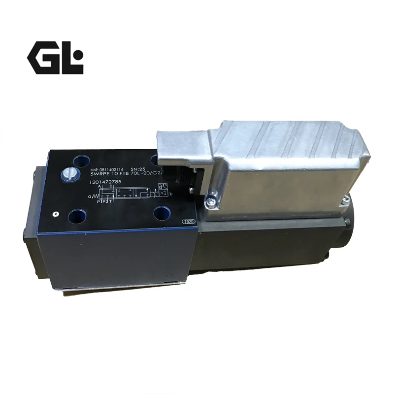
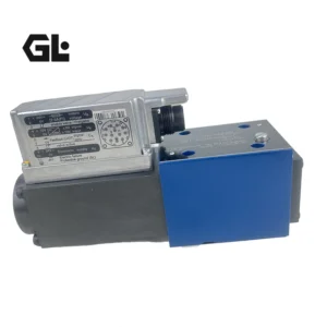
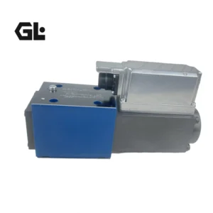

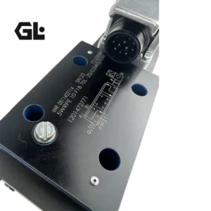

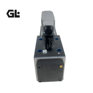
5WRPE High-response Directional Valve 5WRPE10F1B70L-20/G24K0/B 5WRPE 10 F1B 70L-2X/G24K0/A1M Hydraulic Valve


Comprehensive Analysis of 5WRPE10F1B70L-20/G24K0/B Hydraulic Valve
I. Product Attributes
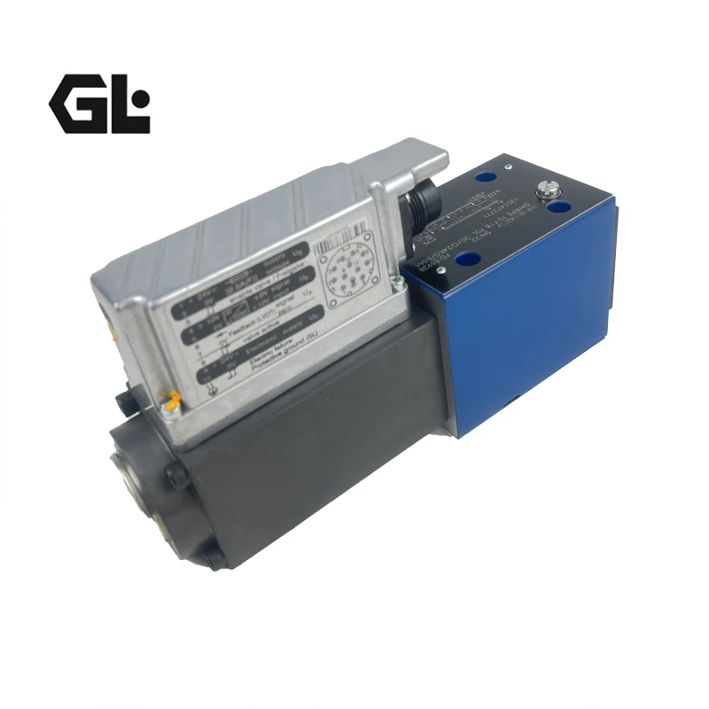
Type: Direct-acting high-frequency response proportional directional valve, with electrical position feedback and integrated electronic control unit (OBE)
Diameter: NG10 (10mm)
Maximum working pressure
P1, P2, A, B ports: 210 bar
Port T: 50 bar
Rated flow: 70 L/min (Δp=5 bar)
Control form: Single electromagnet control (monostable state), spring return
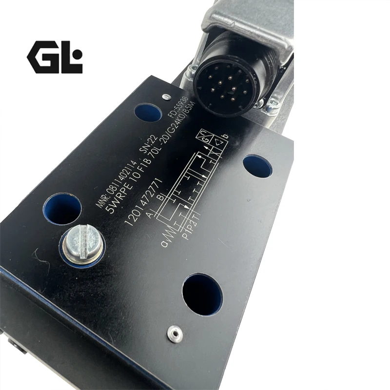
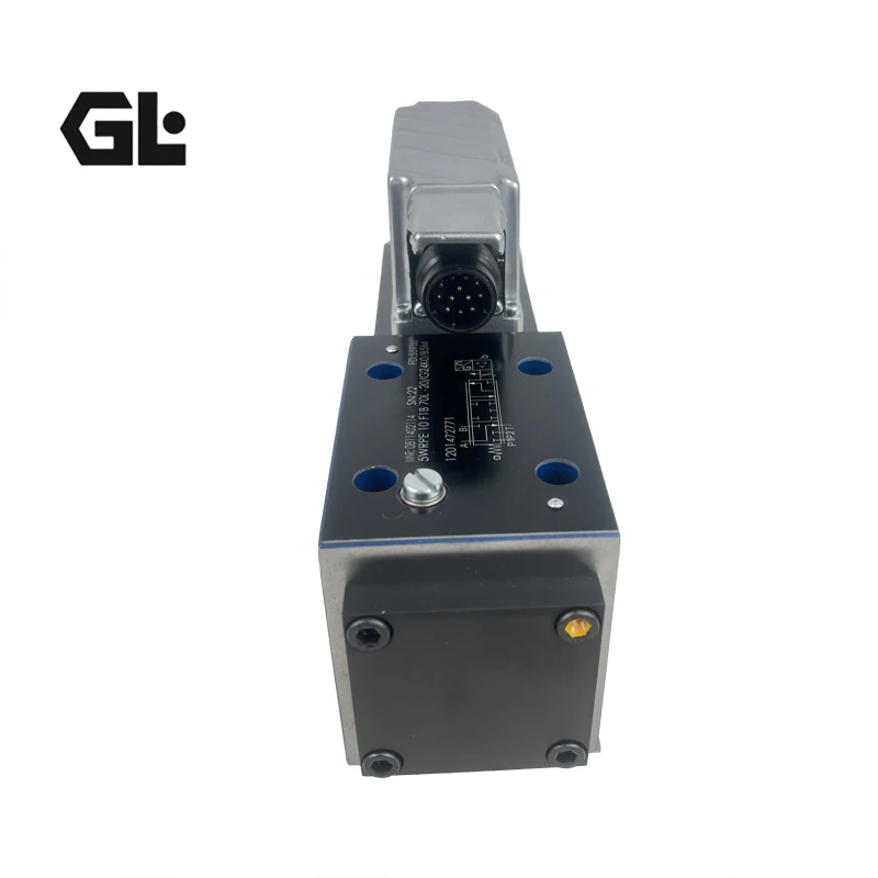
Electrical interface: 6P+PE, with F1 type interface (4-20mA)
Operating temperature: -20℃ to + 60℃
Protection grade: IP65
Weight: Approximately 6.5kg (excluding electrical connections)
I. Product Attributes
Type: Direct-acting high-frequency response proportional directional valve, with electrical position feedback and integrated electronic control unit (OBE)
Diameter: NG10 (10mm)
Maximum working pressure
P1, P2, A, B ports: 210 bar
Port T: 50 bar
Rated flow: 70 L/min (Δp=5 bar)
Control form: Single electromagnet control (monostable state), spring return
Electrical interface: 6P+PE, with F1 type interface (4-20mA)
Operating temperature: -20℃ to + 60℃
Protection grade: IP65
Weight: Approximately 6.5kg (excluding electrical connections)
Ii. Product Features
Feature description
The high-precision flow control accuracy reaches ±1%, the response time is less than 15ms, and the hysteresis is less than 0.5%
Integrated electronic components (OBE) with built-in amplifiers eliminate the need for external controllers and simplify wiring
The electrical position feedback adopts LVDT displacement sensors to achieve closed-loop control and enhance stability
The energy-saving design does not require pilot oil and can drive directly, reducing energy consumption
High response characteristics with high-frequency response (>100Hz), suitable for rapid dynamic control
The safety function automatically resets to a safe position when the power is cut off
Compact direct-acting design, small in size and easy to install
Multiple signal interfaces support two control signals: F1 (4-20mA) and A1 (±10V)
Iii. Working Principle
Core mechanism: Electrical – mechanical – hydraulic energy conversion to achieve proportional control
Electrical signal reception
The control signal (4-20mA or ±10V) is input into the OBE through the electrical interface
OBE compares the input signal with the feedback signal of the actual position of the valve core to calculate the deviation
Mechanical conversion
The OBE drives the proportional electromagnet based on the deviation signal, generating a thrust proportional to the current
The thrust overcomes the force of the reset spring, driving the valve core to move axially
The displacement of the valve core is precisely proportional to the input signal
Hydraulic control
The movement of the valve core changes the opening degree of the valve port, regulating the flow and direction of the oil
Through specially designed valve sleeve and valve core structures, progressive flow characteristics are achieved
The displacement sensor monitors the position of the valve core in real time, forming a closed-loop control to ensure accuracy
Iv. Function and Role
Precise direction control
The direction of the liquid flow is switched according to the polarity of the electrical signal to control the forward and reverse rotation of the actuator (cylinder/motor)
Flow ratio adjustment
The flow rate is strictly proportional to the amplitude of the electrical signal to achieve precise control of the speed of the actuator
Position synchronization control
Multiple valves work in coordination to ensure the synchronous movement of the multi-axis system with an error of less than 0.1mm
Pressure balance control
Maintain system pressure stability through flow regulation to prevent shock and vibration
Safety protection function
When power is cut off, it automatically returns to a safe position to prevent the equipment from malfunctioning
Built-in overload protection to prevent system overpressure
V. Usage Scenarios
Industrial automation
Injection molding machine: Precisely control mold closing, injection speed and pressure to improve molding accuracy
Press: Achieve precise control of pressing force to ensure consistent product quality
Metallurgical equipment: Control the roll gap of the rolling mill to ensure uniform thickness of the sheet
Construction machinery
Excavators/loaders: Precisely control the boom, boom and bucket to enhance operational flexibility and efficiency
Crane: Achieve smooth lifting and precise positioning to ensure operation safety
Shield machine: Precisely control the advancement speed and direction to ensure the accuracy of tunnel construction
Precision processing equipment
CNC machine tools: Control the feed axis and spindle movement to achieve micron-level processing accuracy
Robot: Precisely control joint movement to achieve complex trajectory tracking
Test bench
Hydraulic test bench: Precisely control flow and pressure, simulate various working conditions
Material testing machine: Controls the loading rate and tests the mechanical properties of materials
Vi. Precautions for Installation and Use
1. Preparations before installation
Cleaning system: Thoroughly clean the pipes and interfaces to remove oil stains, iron filings and other impurities. It is recommended to filter the oil with a filter of 20μm or less
Check the model: Confirm that the valve model is consistent with the system requirements (diameter, pressure, flow rate)
Check the oil: Use hydraulic oil (HL or HLP) that meets the requirements, with a viscosity of 13-50mm²/s and a cleanliness level of NAS 9 or below
Environmental inspection: The installation location should be well-ventilated, away from heat sources and vibration sources, with an ambient temperature ranging from -20 ℃ to +60℃
2. Installation points
Correct installation direction: Ensure that the arrow direction of the valve body is consistent with the oil flow direction
Firmly fixed: Use the specified torque to tighten the installation bolts to prevent loosening due to vibration
Electrical connection
Connect the 6P+PE plug to ensure good contact
The power supply is DC24V (indicated by G24), and the grounding is reliable
Control lines and power lines are laid separately to prevent interference
3. Debugging steps
No-load exhaust: Start the system and operate the full stroke of the valve core multiple times under no-load conditions to expel the air in the system
Zero-point calibration
When there is no input signal, adjust the mechanical zero position to ensure that the valve core is in the middle position
Perform electrical zero point calibration using OBE
Stress test
Gradually increase the pressure to 1.25 times the rated pressure, maintain the pressure for 5 minutes, and check for leaks
Adjust the relief valve to the working pressure and lock the adjusting nut
Flow regulation
Input different signal values to test whether the flow output is proportional to the signal
Check the smoothness of the actuator’s movement to avoid crawling
4. Key points for Use and Maintenance
Oil temperature control: The normal operating temperature is 30℃ to 60℃. If the temperature exceeds 80℃, the machine should be shut down to check the cooling system
Regular inspection
Check weekly whether the connections are loose and whether the seals are aged
Clean the valve body surface monthly to prevent the accumulation of oil stains
Oil maintenance
Change the hydraulic oil every 2,000 hours or half a year, and replace the filter at the same time
Regularly test the contamination level of the oil to ensure it meets the requirements
Fault handling
When abnormal noise or vibration occurs, stop the machine immediately for inspection
When replacing the valve core or valve sleeve, it is essential to keep it clean to prevent impurities from entering
Vii. List of 5WRPE Series Models
Model naming rule
plaintext
5WRPE – 10 – F1B – 70L – 20 / G24K0 / B
| | | | | | | |
| | | | | | └ – Plug type (B5M is the standard type)
| | | | | └ — voltage/frequency (G24=24V DC)
| | | | └── Design series (20= series 20)
Flow characteristics (70L=70L/min)
Valve core type (F1B= Specific valve Core Design)
└─────── Diameter (10=10mm)
└──────── Series Number
Key points for selection
Select the flow specification (50L/min, 70L/min, 80L/min, 100L/min) based on the system flow requirements.
Select the type of valve core (F1B, Q5, W6, etc.) according to the control accuracy requirements, as different valve cores have different flow characteristics.
Select the interface form based on the signal type (F1=4-20mA, A1=±10V)
Select the plug type based on the installation space and environment (B5M is the standard type).
The 5WRPE series has multiple variants, and the main differences lie in:Path: NG6, NG10, NG16, NG25, etc.
Pressure rating: Up to 25 MPa, 31.5 MPa, 35 MPa, etc.
Electromagnet types: standard type, explosion-proof type, type with position sensor, etc.
Control options: No amplifier (external required), with analog amplifier, with digital amplifier (if compatible with SSC network).
Common model examples
5WRPE 6 … /… Low-traffic applications.
5WRPE 10 … /… Standard model (such as the model in this question).
5WRPE 10 H … /… Higher pressure version.
5WRPE 10 W4 … /… Version with digital bus interface (such as SSC).
5WRPE 10 … /G24K0/V: Different revised versions or special options.
5WRPE 16 … /… For systems with larger traffic volumes.