

Product Overview
The Danfoss 90L100HS1BC80S3S1E03GBA353528 is a Series 90, 100 cc/rev closed-circuit variable displacement axial piston pump configured for hydrostatic transmission applications.
The Series 90 platform uses a cradle swashplate architecture with a parallel axial piston/slipper design. An integrated charge pump supplies make-up flow, cooling flow, filtration flow and control pressure for the closed hydraulic loop. Danfoss positions the Series 90 family as a compact, high-power-density variable displacement platform for demanding hydrostatic systems.
The model code can be decoded as follows: 90L identifies the 100 cc counterclockwise configuration; HS identifies Hydraulic Displacement Control; 1 specifies pressure limiting on ports A and B; BC is the SAE-B auxiliary mounting pad with 13-tooth coupling; 80 is the twin-port end cap; S is suction filtration; 3 means no displacement limiters; S1 is a 14-tooth, 12/24-pitch splined shaft; E is a 20 cc/rev charge-pump configuration; 03 is the HDC control-orifice option; GBA specifies CP15 + 0.5° valve plate; and 35-35-28 represents 350 bar pressure settings on ports A and B with a 28 bar charge-pressure setting.
For aftermarket replacement projects, this configuration should be matched by displacement, rotation, control type, shaft, mounting interface, port arrangement, filtration and pressure settings, rather than by the 90L100 frame designation alone.
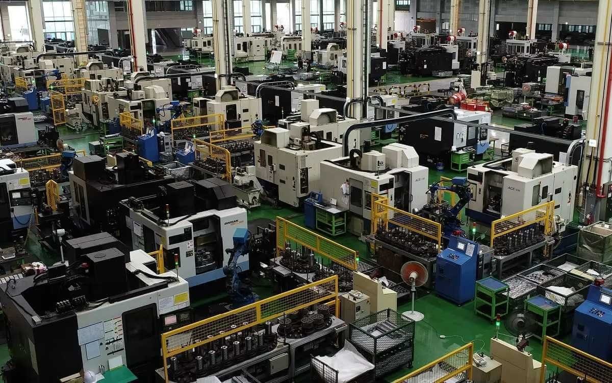
Our replacement units can additionally undergo 100% simulated working-condition testing to verify displacement control, pressure response, charge-pump performance and operating stability before shipment.
Technical Specifications
- Model: 90L100HS1BC80S3S1E03GBA353528
- Brand: Danfoss
- Product Family: Series 90
- Pump Type: Closed-circuit variable displacement axial piston pump
- Displacement: 100 cm³/rev
- Rotation: Left-hand / Counterclockwise
- Rated Speed: 3300 rpm
- Maximum Speed: 3650 rpm
- Theoretical Flow at Rated Speed: approximately 330 L/min
- Maximum Working Pressure: 450 bar / 6525 psi
- Maximum Pressure: 480 bar / 6960 psi
- Configured Port A Pressure Setting: 350 bar / 5075 psi
- Configured Port B Pressure Setting: 350 bar / 5075 psi
- Pressure Regulation Code
1: Pressure limiter for Ports A and B, selectable within the 140–450 bar range - Control Type: HS Hydraulic Displacement Control (HDC)
- HS Signal Pressure Range: 6 ± 0.5 bar to 18 ± 0.5 bar
- Maximum Allowable Control Signal Pressure: 60 bar
- Auxiliary Mounting Pad
BC: SAE-B, 13-tooth coupling - End Cap
80: Twin ports - Filtration
S: Suction filtration - Displacement Limitation
3: No limiters - Input Shaft
S1: 14 teeth, 12/24-pitch splined shaft - Charging System
E: 20 cm³/rev nominal charge-pump flow - Control Orifice
03: HDC, 0.81 mm inlet orifice and 1.3 mm P/drain passages - Special Hardware
GBA: CP15 + 0.5° valve plate - Charge Pressure Setting
28: 28 bar - Reference Weight: 68 kg is the published Series 90 100 cc reference weight with MA control; the exact HS configuration weight should be verified from the specific assembly documentation.
Important Pressure Note
The 350 bar figures are the pressure settings encoded into this specific model. They should not be confused with the 450 bar Series 90 maximum working pressure or 480 bar maximum pressure stated for the 100 cc frame. In other words, the product should not be marketed as a pump factory-set to 450 bar merely because the series has that pressure capability.
Key Technical Advantages
1. 100 cc High-Power-Density Closed-Circuit Architecture
The Series 90 uses a cradle swashplate variable displacement design with parallel axial pistons and slippers. At the 100 cc frame’s 3300 rpm rated speed, the theoretical output flow is approximately 330 L/min, providing substantial hydraulic power density for hydrostatic drives.
2. HS Hydraulic Displacement Control
The HS configuration uses hydraulic displacement control to operate a four-way servo valve and position the swashplate. A mechanical feedback mechanism links actual swashplate position back to the control valve, providing repeatable displacement control relative to the hydraulic input signal. Danfoss describes HDC as a high-gain control with precise displacement positioning.
3. Dual-Side 350 bar Pressure-Limiter Configuration
The 1 pressure-regulation option provides pressure limiting on Ports A and B, with a published selectable range of 140–450 bar. The 35-35 code sets both sides to 350 bar on this specific configuration.
4. Integrated 20 cc/rev Charge Pump
The E charging-system code specifies a 20 cm³/rev nominal charge-pump configuration. The integrated charge pump supplies make-up flow, maintains positive low-loop pressure, and supports cooling, filtration and control functions.
5. CP15 + 0.5° Valve Plate Configuration
GBA is a specific Danfoss ordering-code configuration for a CP15 + 0.5° valve plate. For replacement applications, this configuration is important because the correct valve-plate specification affects the hydraulic unit’s internal flow and control characteristics.
6. Defined Shaft and Auxiliary-Drive Interfaces
The S1 shaft uses a 14-tooth, 12/24-pitch spline, while the BC auxiliary mounting pad uses an SAE-B, 13-tooth coupling. These interfaces are critical when replacing a pump within an existing mechanical package.
7. Suction-Filtration Configuration
The S code specifies suction filtration. Danfoss recommends controlling hydraulic-fluid cleanliness to ISO 4406 22/18/13 or better under normal operating conditions and warns that a clogged suction filter can cause cavitation and damage the charge pump.
8. Engineering Focus for Equivalent Replacement
A technically correct replacement should reproduce the critical interfaces and functional characteristics, including:
- Cylinder block and piston/slipper fit
- Swashplate and slipper contact conditions
- Valve-plate interface
- Servo feedback and neutral positioning
- S1 shaft geometry and concentricity
- BC auxiliary-drive alignment
- Port A/B pressure-limiter settings
- HS signal-pressure-to-displacement relationship
For this reason, 100% simulated working-condition testing is valuable as a final quality-control step for an equivalent replacement unit.
Application Areas
The Danfoss Series 90 is designed for closed-circuit hydrostatic transmission systems. Typical applications include:
- Skid Steer Loaders
- Trenchers
- Asphalt Pavers
- Agricultural and Windrower Machinery
- Aerial Lifts
- Turf Care Vehicles
- Vibratory Rollers
- Closed-Circuit Hydrostatic Drive Units
Danfoss technical documentation specifically discusses skid steer loaders, trenchers, asphalt pavers, windrowers, aerial lifts, turf care vehicles and vibratory rollers when evaluating Series 90 application loading and duty cycles.
Expert Maintenance Tips
1. Keep the HS Control Circuit Clean
HS is a hydraulic pilot control. Danfoss warns against contamination that can obstruct control operation. The normal HS signal range is 6 ± 0.5 to 18 ± 0.5 bar, while the maximum allowable signal pressure is 60 bar. During commissioning, verify X1/X2 control pressure and contamination control before troubleshooting pump displacement behavior.
2. Treat 28 bar as the Ordered Charge-Pressure Setting
The final 28 in the model code identifies the charge-pressure setting. Danfoss defines this setting under specified reference conditions, including neutral operation at 1800 rpm and 32 mm²/s fluid viscosity. Actual charge pressure must still be verified under the machine’s real speed, load, temperature and swashplate conditions.
3. Protect the Suction Filter
Because this model uses suction filtration, the filter should be maintained with an appropriate contamination monitor and bypass strategy. A restricted suction filter can generate excessive inlet restriction, cavitation and charge-pump damage.
4. Maintain Correct Case Pressure
Series 90 specifies a 3 bar rated case pressure and 5 bar maximum case pressure. The housing should remain filled with hydraulic fluid, and the case-drain circuit should be free of trapped air before operation after extended shutdown.
5. Do Not Over-Torque the L2 Case-Drain Fitting
Danfoss specifies a maximum torque of 100 N·m for the L2 case-drain fitting on the side cover. Excessive torque can affect swashplate neutral position.
6. Respect Rated and Maximum Speed
For the 100 cc frame, 3300 rpm is the rated full-power speed, while 3650 rpm is the maximum permitted speed. Operation between rated and maximum speed should be limited to reduced-power, limited-duration conditions, and maximum speed must never be exceeded.
7. Maintain Hydraulic-Fluid Cleanliness
Danfoss recommends ISO 4406 22/18/13 or better under normal operating conditions. For continuous high-load applications, contamination control directly influences the durability of the pump, charge pump, bearings and control components.