

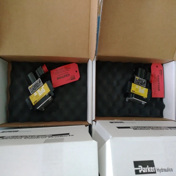
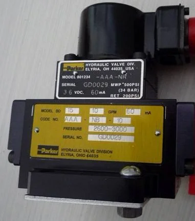

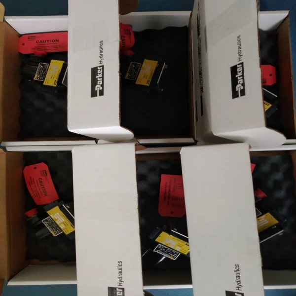
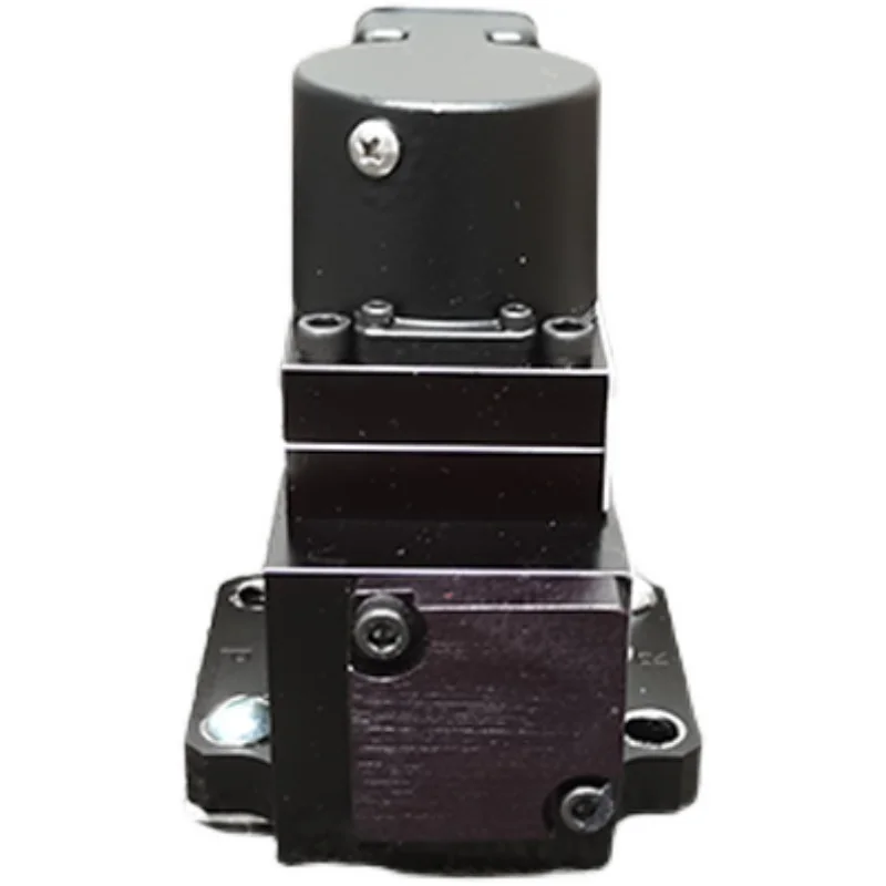
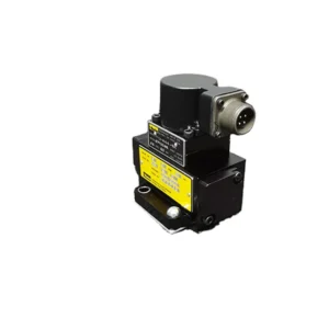

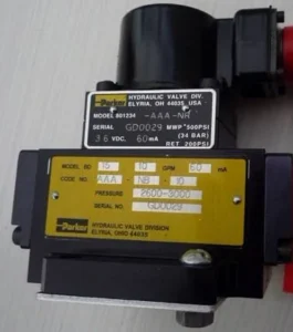
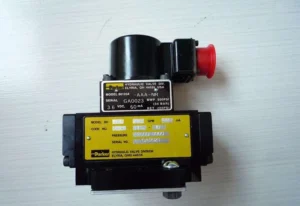

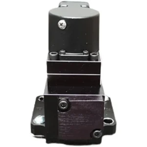
BD15AAANB10 Parker Servo Valve BD Series 3000 PSI
| Model Number | BD15AAANB10, BD15AAANB15, 801234-AFA-NR |
|---|
SKU
N/A
Categories Hydraulic Valve, Servo Valve
Tags air valve, electro-hydraulic servo valve, gas valve, kf valves, ksb valve, kvc valve, lpg valve, mac valve, p v valve, pvc valve, sdv valve, servo motor valve, smc valve, valve, water servo valve
Product Description
Product Overview
The BD15AAANB10 is a two-stage torque motor electro-hydraulic servovalve from Parker Hannifin’s BD Series, manufactured by Parker Hydraulic Valve Division in Elyria, Ohio. This valve employs a mechanical force feedback, two-stage architecture with a twin-nozzle flapper pilot stage and a four-way sliding spool power stage, providing high resolution in the control of position, velocity, and force in motion control applications.
The BD15AAANB10 delivers a rated flow of 10 GPM (37.9 L/min), with an operating pressure range of 2600–3000 psi (approximately 179–207 bar). Standard coil current is 60 mA with 60 Ω coil resistance, and the step response (10% to 90%) is just 26 ms. When paired with Parker BD90 and BD101 series servo amplifiers or a motion controller, the valve provides accurate control of rotary and linear actuators.
As a drop-in replacement, the BD15AAANB10 is fully compatible with the OEM Parker specification in mounting interface, electrical connection (C2B standard connector), and performance characteristics. Model code breakdown: BD15 denotes BD Series S04 size; AA indicates NG10 port connection; AN designates AMP Junior Power Timer (JPT) electrical interface; B10 denotes ±10V adjustment range. Every unit undergoes 100% simulation-based testing prior to shipment, covering null stability, flow linearity, step response, and internal leakage.
Technical Specifications
All parameters below are verified against Parker’s official BD Series product pages and the HY11-3292/UK catalogue:
Complete Model: BD15AAANB10
Brand: Parker Hannifin
Product Series: BD Series two-stage torque motor servovalve
Product Type: Mechanical force feedback, two-stage electro-hydraulic servovalve (twin-nozzle flapper pilot stage)
Size: S04
Rated Flow: 10 GPM / 37.9 L/min (@ ΔP = 70 bar)
Maximum Flow: 15 GPM (series maximum)
Operating Pressure Range: 2600 – 3000 psi (approx. 179 – 207 bar)
Maximum Operating Pressure: 3000 psi / 210 bar
Coil Current: 60 mA (standard)
Coil Resistance: 60 Ω (each coil)
Electrical Connection: C2B standard connector
Command Signal: ±10 V DC
Step Response (10%→90%): 26 ms
Hysteresis: ≤ 3%
Non-linearity: ≤ 5%
Threshold: ≤ 0.5%
Operating Temperature Range: -1 °C to +82 °C
Hydraulic Fluid: Mineral oil (60 – 225 SSU, 1000 SSU maximum)
Filtration Requirement: SAE Class 3 or better, ISO Code 17/15/12
Seal Material: Nitrile
Body Material: Grey Iron
Protection Class: NEMA 1 (IP54)
Typical Internal Leakage (Null): 1.5 – 2.1 L/min (BD15 standard spool lap)
Weight: Approx. 2.9 kg (typical for S04 size)
Note: Specifications are based on Parker’s official BD Series product pages and catalogue HY11-3292/UK. Different model codes vary in rated flow, coil resistance, connector type, and seal material. Always verify against the complete model code during selection. Part number 801234-AFA-NR is a related Parker internal reference number for this model.
Key Technical Advantages
1. Twin-Nozzle Flapper Pilot Stage with Mechanical Force Feedback for High-Resolution Control
The BD15AAANB10 employs a classic twin-nozzle flapper pilot stage driving a power spool in a two-stage architecture. The torque motor receives an electrical signal and generates a minute torque that deflects the flapper between two nozzles, creating a differential pressure across the spool ends that drives spool displacement. Spool displacement is mechanically fed back to the torque motor through a feedback spring, establishing a closed-loop torque balance. This mechanical feedback mechanism does not rely on electronic sensors, offering exceptional immunity to electromagnetic interference and long-term stability, with resolution capable of sub-micron spool displacement control.
2. Reduced Contaminant Sensitivity for Demanding Industrial Environments
The BD Series servovalves were specifically engineered to address contaminant sensitivity in industrial market applications. Parker’s official documentation explicitly states the series offers “Reduced contaminant sensitivity”. The twin-nozzle flapper configuration features optimally sized nozzle orifices, combined with built-in filtration protection in the pilot stage circuit, effectively reducing the risk of nozzle clogging and spool sticking caused by fluid contamination. This makes the valve particularly well-suited to high-dust, high-contamination environments such as blast furnace equipment, TRT gas control valves, and steelmaking dry dust removal switching stations.
3. Linear Flow Gain Characteristics and Fast Dynamic Response
The BD15AAANB10 exhibits linear flow gain characteristics, maintaining a well-defined linear relationship between flow output and control current, which facilitates closed-loop control system tuning. The step response (10%→90%) of just 26 ms satisfies high-frequency dynamic loading and rapid position switching requirements. Fast step response with minimal overshoot makes this valve suitable for electro-hydraulic servo systems with demanding dynamic performance requirements.
4. High-Strength Grey Iron Body and Precision-Lapped Spool Assembly
The valve body is constructed from grey iron, offering excellent rigidity and vibration damping characteristics to withstand structural stresses under high-pressure operation. The power stage spool and sleeve are manufactured from high-strength alloy steel through multiple precision lapping operations, with clearance tolerances held to stringent specifications. The sharp-edged metering lands and sleeve windows ensure predictable and repeatable flow-pressure characteristics. Nitrile seals provide excellent resistance to mineral oil-based hydraulic media.
5. Broad Flow Coverage and System Compatibility
The BD15AAANB10 belongs to the BD15 size series, which covers rated flows of 1, 2.5, 5, 10, 15, and 20 GPM, allowing users to select the appropriate variant based on system requirements. The valve is fully compatible with Parker BD90 and BD101 series servo amplifiers and PMC series motion controllers, enabling system integrators to leverage existing controller solutions without redesigning drive circuits.
Application Areas
Steel & Metallurgy: Blast furnace equipment, TRT gas control valves, steelmaking dry dust removal switching station servo control circuits
Axial Fan Units: Servo motor control, mounted on valve stands or servo motor manifolds
Industrial Automation Lines: Integration with PLC and motion controllers for precision position, velocity, and force closed-loop control
Material Testing Systems: Electro-hydraulic servo fatigue test rigs, structural dynamic loading systems
Injection Molding Machines: Precision flow and pressure control during injection and hold-pressure phases
Die Casting Equipment: High-speed dynamic pressure regulation and real-time switching control
Power Generation: Steam turbine control, gas turbine servo actuators
General Hydraulic Systems: Suitable for general hydraulic applications requiring high-resolution motion control
Expert Maintenance Tips
Pre-Installation Checks:
Verify the manifold mounting surface conforms to NG10 (ISO 4401) standard; surface roughness Ra ≤ 0.8 μm
Flush all piping with clean hydraulic fluid prior to installation; ensure system cleanliness reaches ISO 4406 17/15/12 or better
Inspect nitrile O-rings for damage and confirm compatibility with the hydraulic fluid in use
Tighten mounting bolts in diagonal sequence to specified torque to prevent valve body distortion and spool binding
Operational Maintenance:
Use a 3 μm absolute-rated pressure filter, specified without bypass and equipped with a contamination indicator
For mineral oil operation, ISO VG 46 is recommended; maintain operating viscosity within 60 – 225 SSU
Maintain fluid temperature within -1 °C to +82 °C; avoid overheating that accelerates seal degradation and fluid breakdown
Periodically monitor internal leakage: typical null leakage is 1.5 – 2.1 L/min (BD15 standard spool lap). Significant increase indicates spool/sleeve wear
Verify coil resistance remains stable at 60 Ω; confirm C2B connector contacts are clean and secure, free from oxidation or looseness
Troubleshooting Guide:
Spool fails to actuate: Verify command signal (±10 V DC) reaches the coil; measure coil resistance against the 60 Ω rating; confirm connector engagement is reliable
Null-point drift: After ruling out fluid contamination, inspect feedback spring for fatigue or fracture; verify nozzle-flapper clearance has not changed due to wear
Slow response: Check system cleanliness level; verify nozzles and orifices are not partially blocked by contaminant particles
Insufficient flow: Confirm system supply pressure is within 2600–3000 psi range; check power stage spool for contamination-induced binding


Company Profile

Frequently Asked Questions
1.What ls our Main Products?
1.Hydraulic pump
2.Hydraulic valve
3.Hydraulic motor
4.Hydraulic cylinder
5.Hydraulic parts
2. What about the MOQ?
3.What are your advantages?
- Adhere to quality first.
- Support customization, ODM & OEM service.
- 1-year warranty and complete after-sales support.
- Safe and fast shipping worldwide.
- 24-hour online service for your inquiries.
4.Are you a manufacturer? What’s your delivery time?
Yes, we are a manufacturer with our own factory.
Common models are in stock, and orders are usually shipped within 1–3 days.
5.Which payment methods are accepted?
We accept T/T, L/C, PayPal, VISA, Western Union, Apple Pay, Google Pay, Afterpay (Clearpay), Klarna, and Trade Assurance.
For full orders: 30% deposit, balance before shipment.
For small/sample orders: full payment in advance.
6.How will you deliver my goods?
We offer flexible shipping options: DHL, UPS, FedEx, TNT, EMS, as well as air or sea freight.
All deliveries ensure door-to-door fast and safe service.
7.How do you inspect and guarantee your products?
All products are tested before shipment to ensure perfect working condition.
We offer a 12-month warranty — if a product fails due to quality issues, we provide free spare parts or repair support.
8.What about after-sales service?
If you encounter any problem during use, please contact your sales manager or our support team at any time.
We will respond quickly and help solve the issue efficiently.
9.What are your main applications?
- Hydraulic systems
- Agricultural machinery
- Construction machinery
- Automobile industry
- Local distributors and maintenance centers
10.Can I get a discount for bulk orders?
Yes. We offer competitive wholesale prices and try our best to give benefits to long-term partners.
Shoot Us An Email
Professional Manufacturer