


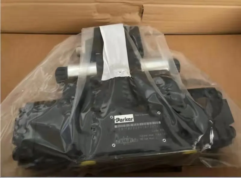




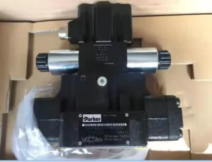
Product Overview
The Parker D1FVE02CC0NM0314 is a direct-operated proportional pressure reducing valve from the D1FV family. It is designed for electrically adjustable hydraulic pressure control rather than conventional directional flow switching.
Parker’s official D1FV documentation defines the series as proportional pressure reducing valves using a barometric feedback principle to control pressure at the A or B port. The OBE version integrates digital electronics inside a robust metal housing and supports configurable control functions.
For the exact model D1FVE02CC0NM0314, published industrial records identify the following configuration:
- D1FV OBE proportional pressure reducing valve
- NG06 / CETOP 03
- 25 bar pressure range
- 0…±10 V input
- 0…+10 V → P-B function
- NBR seals
- 6 + PE electrical connection
- approximately 2.9 kg weight.
The Parker D1FV family also includes a 45 bar pressure version, but that configuration must not be transferred to this exact 25 bar model.
Public industrial inventory records currently identify D1FVE02CC0NM0314 as discontinued by the manufacturer, making this model particularly relevant for legacy-equipment service, replacement sourcing and OEM interchangeability programs.
Technical Specifications
- Model: D1FVE02CC0NM0314
- Manufacturer: Parker Hannifin
- Series: D1FV
- Product Type: Direct-operated proportional pressure reducing valve
- Electronics: On-board electronics (OBE)
- Nominal Size: NG06
- Interface: CETOP 03 / NFPA D03
- Mounting: Subplate mounting
- Mounting Position: Unrestricted
- Actuation: Proportional solenoid
- Feedback Principle: Barometric feedback
- Pressure Range: 25 bar
- Maximum Operating Pressure: 350 bar at P/A/B for the D1FV series
- Maximum T-Port Pressure: 185 bar
- Maximum Flow: 10 L/min
- Minimum Primary Pressure: 30 bar
- Input Signal: 0…±10 V
- Control Function: 0…+10 V → P-B
- Seal Material: NBR
- Electrical Connection: 6 + PE
- Fluid: Hydraulic oil according to DIN 51524…51535
- Fluid Temperature: -20 to +40 °C
- Permitted Viscosity: 20 to 380 mm²/s
- Recommended Viscosity: 30 to 80 mm²/s
- Fluid Cleanliness: ISO 4406 Class 18/16/13
- Hysteresis: <4%
- Solenoid Current Temperature Drift: <0.02%/K
- Duty Cycle: 100% ED
- Protection: IP65 with correctly mounted compliant connector
- Supply Voltage: 12 V DC
- Current Consumption: 2.2 A
- Coil Resistance: 4.4 Ω
- Coil Insulation Class: Class F
- Approximate Weight: 2.9 kg
- Displacement: Not applicable
- Maximum Speed: Not applicable
- Peak Pressure: No separate peak-pressure value is specified. The 25 bar figure is the pressure-control range, while 350 bar is the maximum operating pressure of the D1FV hydraulic design.
Key Technical Advantages
1. Direct proportional pressure regulation
The D1FVE02CC0NM0314 uses a proportional solenoid to regulate hydraulic pressure directly.
Parker defines the D1FV as a direct-operated proportional pressure reducing valve, making it suitable for applications requiring continuously adjustable pressure rather than simple on/off switching.
2. Barometric feedback
The D1FV uses the barometric feedback principle for pressure regulation.
This feedback architecture supports improved repeatability and pressure-control stability compared with purely force-balanced proportional valve arrangements. Parker specifically lists high repeatability and low hysteresis among the main D1FV characteristics.
3. Defined 25 bar control range
The exact D1FVE02CC0NM0314 configuration is identified as the 25 bar pressure-range version. The D1FV product family also includes a 45 bar version, but those two pressure ranges must not be mixed.
This makes the exact model more appropriate for lower-range proportional pressure regulation and pilot-control applications.
4. 0…±10 V analog control
The exact model is associated with a 0…±10 V input, with a published functional relationship of 0…+10 V → P-B.
This provides straightforward integration with PLC analog outputs and industrial motion-control systems.
5. Integrated onboard electronics
The D1FV OBE design integrates digital control electronics inside a robust housing.
Parker states that the nominal parameters are factory-set and provides an RS-232 interface for parameterization.
For legacy equipment, this integrated architecture can simplify replacement by reducing the need for an external proportional amplifier.
6. Low hysteresis and repeatability
Parker lists low hysteresis and high repeatability from valve to valve as key product characteristics, with the published D1FV hysteresis specified below 4%.
This is valuable for industrial processes requiring repeatable pressure settings.
7. Standard NG06 / CETOP 03 mounting
The NG06 / CETOP 03 interface allows the valve to be integrated into standardized hydraulic manifolds and subplates.
For OEM replacement applications, however, dimensional interchangeability alone is insufficient. The pressure range, P-B control function, input signal, sealing material and dynamic performance must also be matched.
8. Cast-iron body construction
D1FV product documentation specifies a cast-iron body and provides NBR and FPM seal options.
For long-term service performance, spool-to-bore accuracy, surface finish, solenoid consistency and hydraulic cleanliness are as important as the external body material.
9. Strong legacy replacement value
Because public industrial records identify D1FVE02CC0NM0314 as discontinued, the model is particularly relevant for replacement sourcing and maintenance of older Parker hydraulic systems.
Our replacement engineering can target:
- mounting-interface compatibility
- P-B functional matching
- 25 bar pressure range
- ±10 V command compatibility
- NBR seal compatibility
- electrical-interface matching
- pressure-response verification
Each replacement unit can then undergo 100% simulated operating-condition testing before shipment.
Application Areas
Typical applications include:
- Industrial hydraulic power units
- Automated hydraulic control systems
- Hydraulic clamping circuits
- Precision hydraulic tooling
- Machine-tool auxiliary hydraulics
- Injection-molding auxiliary circuits
- Plastic-processing machinery
- Low-range pilot pressure control
- Proportional pressure-control modules
- Legacy imported hydraulic equipment
- Parker legacy hydraulic systems
- OEM replacement assemblies
The actual machine circuit should be checked carefully because the exact model is associated with the 0…+10 V → P-B control function.
Expert Maintenance Tips
1. Separate pressure range from maximum operating pressure
The D1FV specification contains several different pressure-related values:
- Pressure range: 25 bar for the exact model
- Maximum operating pressure: 350 bar
- Minimum primary pressure: 30 bar
- Maximum T pressure: 185 bar.
The 350 bar value must not be presented as the adjustable pressure range of D1FVE02CC0NM0314.
2. Verify the ±10 V polarity and P-B function
The exact model is documented as:
0…+10 V → P-B
During commissioning, verify:
- 0 V reference
- positive command
- negative command
- controller polarity
- P-B pressure-control direction
A polarity mismatch can cause pressure regulation in the wrong hydraulic branch.
3. Confirm the 12 V DC electrical version
The published D1FV OBE data specify:
- 12 V DC supply
- 2.2 A current consumption
- 4.4 Ω resistance
The coil must therefore be matched to the original electrical configuration rather than automatically substituted with a common 24 V DC proportional valve coil.
4. Maintain ISO 4406 Class 18/16/13 cleanliness
Parker specifies ISO 4406 Class 18/16/13 fluid cleanliness.
Contamination can alter spool friction and metering behavior and may reduce pressure-control repeatability.
5. Verify minimum primary pressure
The published minimum primary pressure is 30 bar.
When supply pressure falls below the required level, the valve may not establish the commanded regulated pressure even if the electrical signal is correct.
6. Check T-port back pressure
The maximum specified T-port pressure is 185 bar.
Return-line pressure should be measured during dynamic operation, especially where several valves share a common return manifold.
7. Use the correct RS-232 parameterization method
Parker specifies RS-232 for OBE parameterization and explicitly warns against directly using a standard USB cable, which can damage the PC or valve electronics.
8. Perform full dynamic validation after replacement
Recommended tests include:
- 12 V DC supply verification
- 0…±10 V command verification
- P-B pressure-control direction
- 0%, 25%, 50%, 75% and 100% command points
- 25 bar range verification
- primary pressure measurement
- T-port back-pressure measurement
- thermal stabilization
- continuous cycling
For OEM replacement products, 100% simulated operating-condition testing should be used to verify mechanical fit, electrical compatibility, pressure regulation and dynamic performance.