
Product Overview
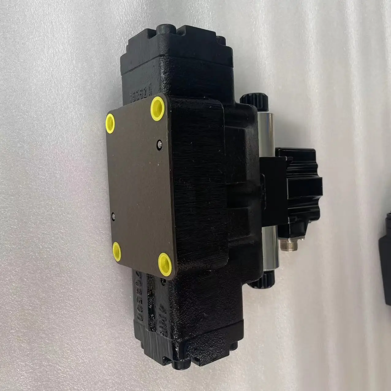
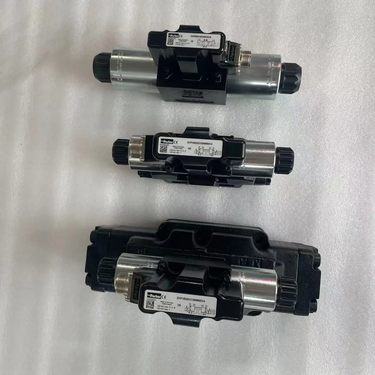
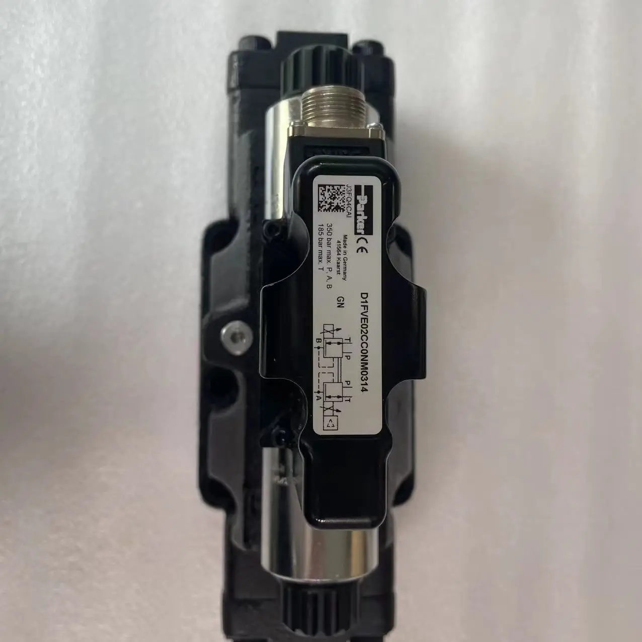
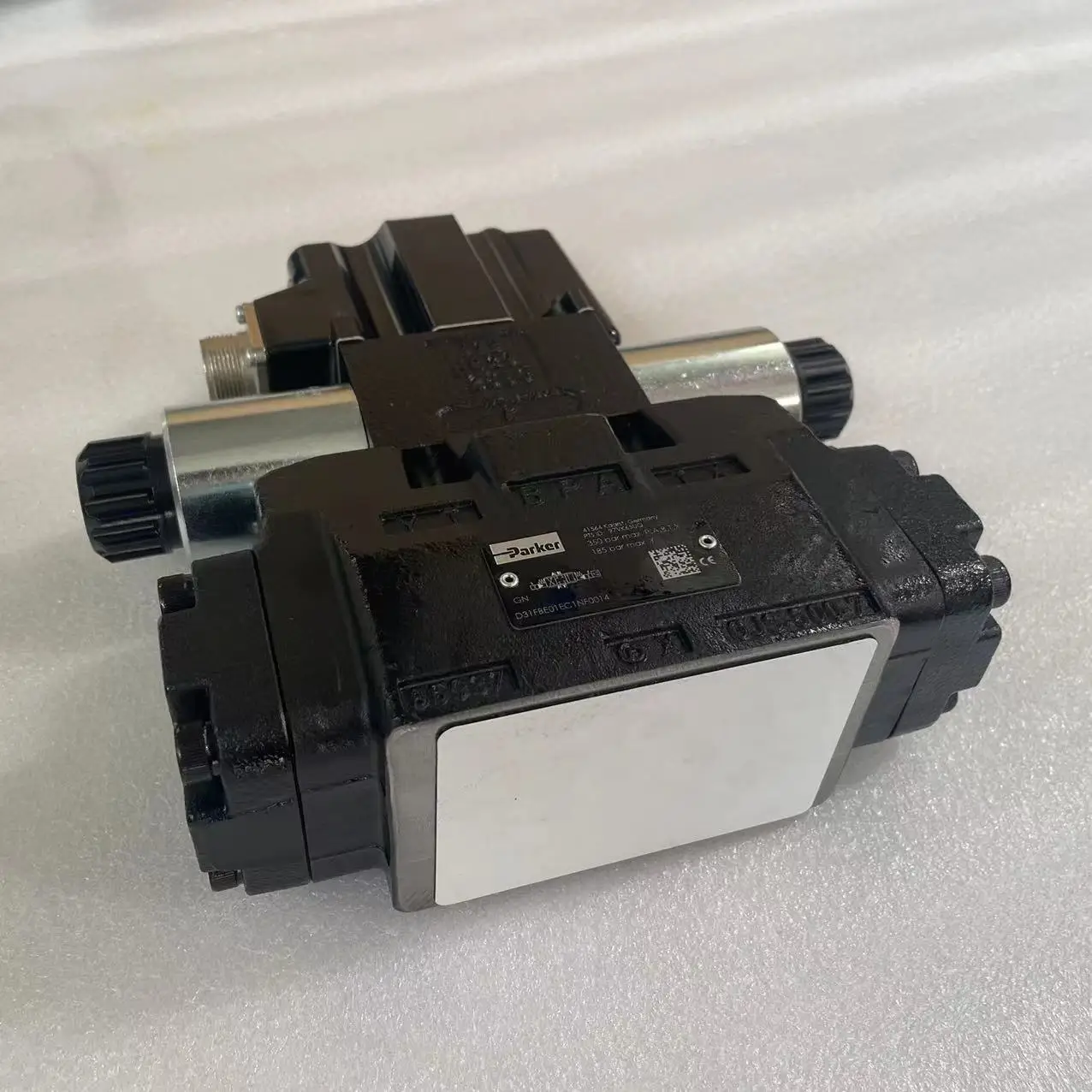
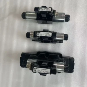
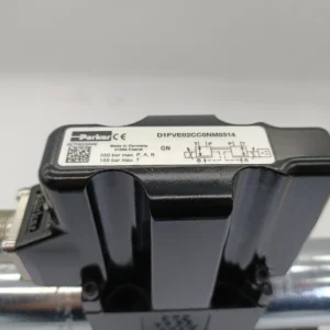
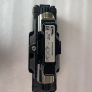
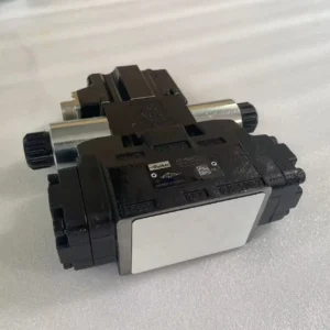
The Parker D1FPE50CJ9NB70 is a direct-operated, high-dynamic proportional directional control valve from the D1FP series. It uses Parker’s VCD® actuator and onboard electronics to provide accurate hydraulic control for position, velocity, and force applications.
The valve is designed for NG06 / CETOP 03 / NFPA D03 mounting interfaces and combines high flow capability with servo-class dynamic response. Parker specifies a frequency response of up to 350 Hz at ±5% input signal, while the D1FP platform is rated for up to 350 bar at ports P, A and B.
For the exact D1FPE50CJ9NB70 configuration, available industrial product data identifies a 6 L/min nominal flow rating, E50C spool, ±10 V input, NBR seals, 6 + PE + Enable electrical connection, and P/A/B/T closed spool position.
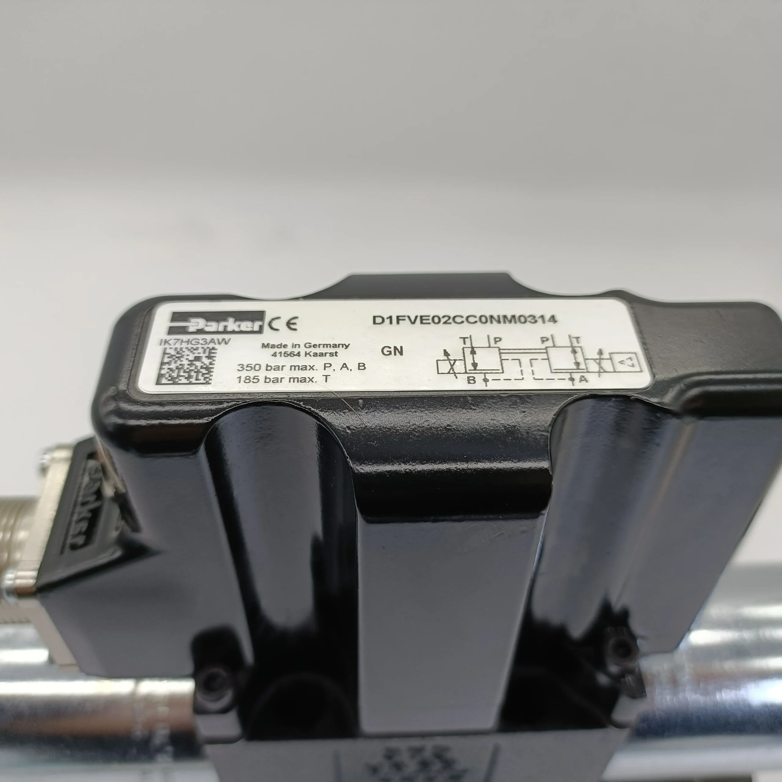
For replacement applications, correct identification of the complete ordering code is essential because D1FP valves are available with different spool types, signal configurations, flow ratings, electrical connections, and fail-position configurations.
Our replacement units are produced with a focus on OEM interchangeability and are subjected to 100% simulated operating-condition testing before shipment to reduce commissioning risk in demanding hydraulic systems.
Technical Specifications
- Manufacturer: Parker Hannifin
- Model: D1FPE50CJ9NB70
- Series: D1FP
- Valve Type: Direct-operated servo proportional DC valve
- Actuator: Parker VCD® actuator
- Nominal Size: NG06 / CETOP 03 / NFPA D03
- Mounting Interface: DIN 24340 / ISO 4401 / CETOP RP121 / NFPA
- Spool Type: E50C
- Nominal Flow: 6 L/min at Δp = 35 bar per control edge
- Maximum Operating Pressure: 350 bar at P, A and B ports
- T Port Pressure: 35 bar with internal drain; up to 350 bar for D1FP with external drain under the specified Y-port arrangement
- Y Port Pressure: 35 bar
- Maximum D1FP Flow Capability: 90 L/min at Δp = 350 bar over two control edges
- Input Signal: ±10 V
- Supply Voltage: DC 22–30 V
- Maximum Current Consumption: 3.5 A
- Pre-Fuse: 4.0 A medium lag
- Electrical Connection: 6 + PE + Enable
- Protection Class: IP65 with correctly mounted plug-in connector
- Step Response: <3.5 ms at 100% step
- Frequency Response: 350 Hz at ±5% input signal
- Hysteresis: <0.05%
- Sensitivity: <0.03%
- Temperature Drift: <0.025%/K
- Recommended Filtration: ISO 4406:1999 18/16/13
- Recommended Viscosity: 30–80 cSt
- Permitted Viscosity: 20–400 cSt
- Hydraulic Fluid: Hydraulic oil according to DIN 51524–51535
- Seal Material: NBR for the identified configuration
- Defined Power-Fail Position: P, A, B and T closed
- Series Weight: Approximately 5.0 kg for D1FP
The engineering data above combines Parker’s official D1FP/D3FP catalog data with the identified configuration of D1FPE50CJ9NB70. The 6 L/min figure is the model’s nominal flow rating, while 90 L/min is a D1FP series maximum under a defined 350 bar pressure-drop condition and should not be presented as the normal flow rating of this exact model.
Key Technical Advantages
VCD® Servo-Class Dynamic Response
The Parker VCD® actuator is designed to deliver servo-valve-like dynamic behavior. The D1FP platform reaches 350 Hz frequency response, making it suitable for high-speed hydraulic axes, rapid positioning and short-cycle industrial machinery.
High-Pressure Differential Capability
The D1FP is specified for applications with pressure drops up to 350 bar across the valve, while P, A and B ports are rated for a maximum operating pressure of 350 bar. This makes the architecture suitable for demanding high-pressure hydraulic control systems.
Low Hysteresis and High Sensitivity
Parker specifies hysteresis below 0.05%, sensitivity below 0.03%, and temperature drift below 0.025%/K. These characteristics support stable and repeatable hydraulic motion control.
Fast Step Response
With a specified step response of less than 3.5 ms for D1FP valves, the valve can rapidly establish commanded hydraulic flow, helping reduce machine cycle times.
Standardized NG06 Interface
The D1FP uses the widely adopted NG06 / CETOP 03 / NFPA D03 interface and conforms to DIN 24340, ISO 4401, CETOP RP121 and NFPA mounting standards, simplifying integration into standardized hydraulic manifolds.
Defined Power-Off Spool Position
The identified D1FPE50CJ9NB70 configuration uses a closed center position with P, A, B and T closed. This provides a clearly defined hydraulic state when electrical power is removed.
Application Areas
- Machine tools
- Hydraulic positioning axes
- General industrial presses
- Blow molding machines
- High-speed hydraulic motion systems
- Force and velocity control systems
- Precision hydraulic actuators
- Marine diesel fuel injection and exhaust valve control
These application areas are consistent with documented D1FP applications and the valve’s high-dynamic proportional control architecture.
Expert Maintenance Tips
Verify the Complete Electrical Code
The D1FPE50CJ9NB70 uses a ±10 V command signal and 22–30 V DC supply. Always match the complete ordering code rather than selecting a replacement solely by body size or connector appearance.
Maintain Hydraulic Cleanliness
Maintain filtration at ISO 4406:1999 18/16/13 or better. High-dynamic proportional valves are particularly sensitive to contamination that can increase spool friction, delay response and affect repeatability.
Control T and Y Port Pressure
High return pressure applications must follow Parker’s specified drain configuration. When higher T-port pressure is required, the external Y-port arrangement must be implemented according to the manufacturer’s hydraulic connection requirements.
Protect the Electrical Signal
Use properly shielded and grounded wiring and keep command wiring away from high-current power cables where practical. Stable command quality is essential for maintaining proportional accuracy.
Perform Dynamic Commissioning
After installation, verify:
- Zero-position behavior
- Positive and negative ±10 V response
- Flow symmetry
- Step response
- Pressure build-up
- Power-loss spool position
- External and internal leakage
- Hydraulic oil temperature
For precision hydraulic axes, a dynamic test under simulated or actual load is recommended rather than relying only on a static electrical test.