
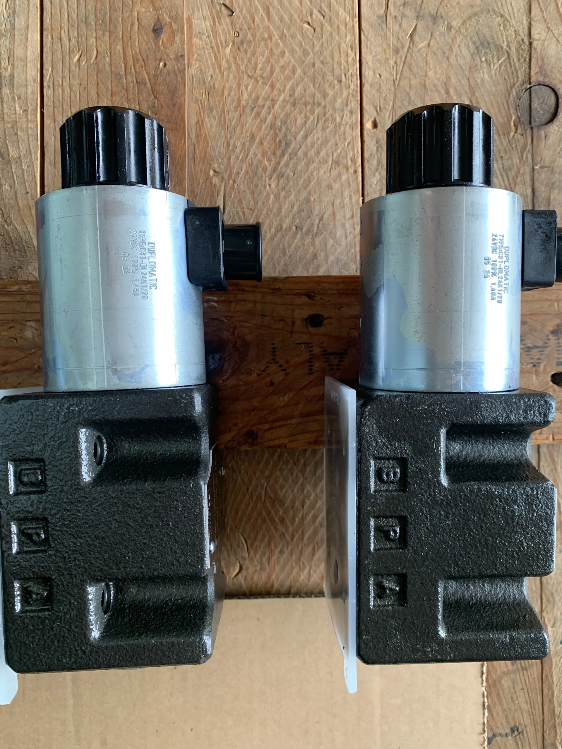
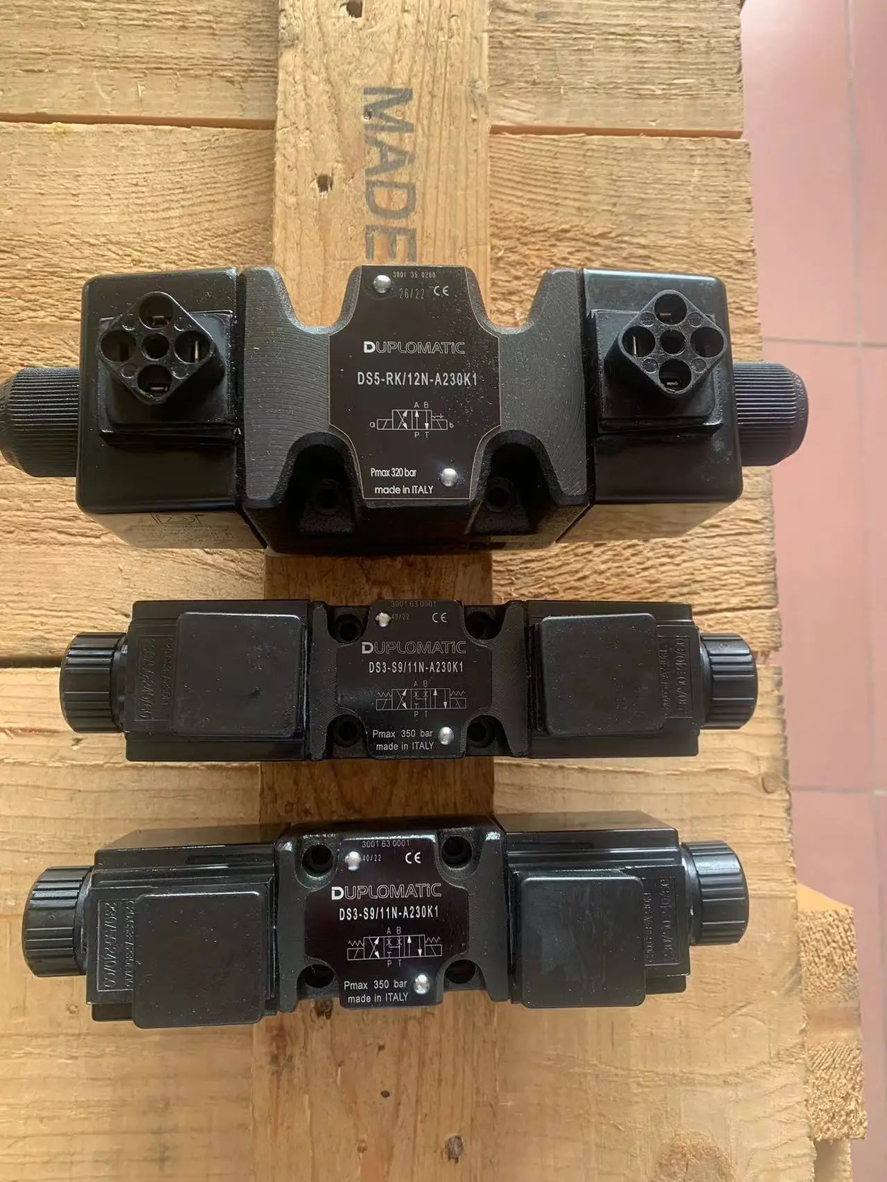
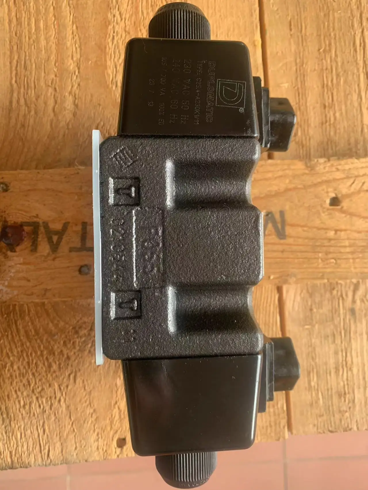

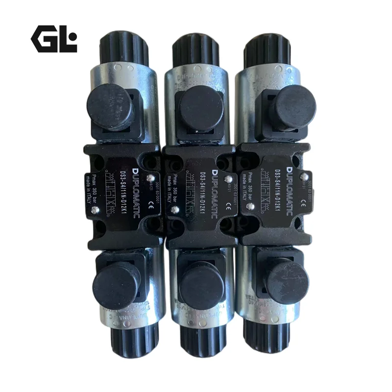
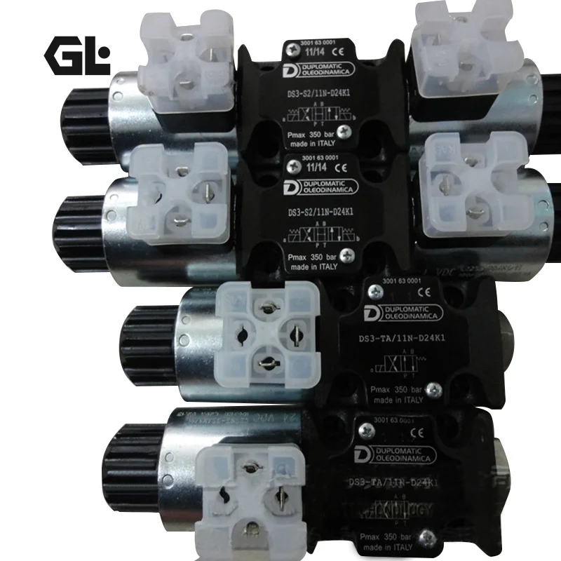
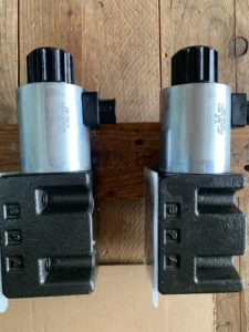
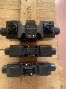
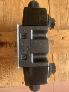
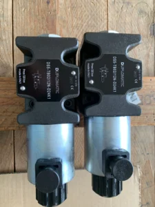
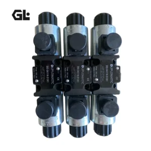

DS3-S20 Rexroth Solenoid Directional Valve 100 L/min 350 Bar
| Model Number | DS3-S20/11N-D24K1, DS3-SA1/11N-D24K1, DS3-SA2/11N-D24K1 |
|---|
SKU
N/A
Categories Directional Valve, Hydraulic Valve
Tags 12v hydraulic valve, air valve, cross hydraulic valve, danfoss hydraulic valves, gas valve, hydraulic control valve, hydraulic directional control valves, hydraulic dump valve, hydraulic flow control valve, hydraulic solenoid valve, ksb valve, lpg valve, mac valve, rexroth hydraulic valve, valve
Product Description
Product Overview
The DS3-S20 series direct-acting solenoid directional control valve (model DS3-S20/11N-D24K1) is a high-performance solenoid-operated directional valve manufactured to advanced European hydraulic standards. Belonging to the DS3 series with size 6 (NG6 / CETOP 03), this valve features a direct-acting subplate mounting design conforming to ISO 4401-03 (CETOP RP121H) standards. Actuated by wet armature solenoids, the control spool provides precise directional switching control for hydraulic actuators.
This product is dimensionally and functionally identical to the original Rexroth 4WE6 series and Duplomatic DS3 series valves. Per industry interchange standards, the DS3-S20 directly replaces Rexroth 4WE6 series valves with equivalent spool functions, offering true drop-in interchangeability without modifying piping systems or mounting interfaces. Every unit undergoes 100% bench testing under simulated working conditions, including rated pressure holding, directional response verification, internal leakage measurement, and solenoid response characterization, ensuring performance consistency with the original equipment.
Technical Specifications
General Specifications
Model: DS3-S20/11N-D24K1
Product Series: DS3 (Size 6 / NG6 / CETOP 03)
Spool Type: S20 (All ports closed in neutral)
Design: Direct-acting, subplate mounting solenoid directional valve
Ways/Positions: 4-way, 3-position
Mounting Pattern: ISO 4401-03 / CETOP RP121H
Hydraulic Parameters
Maximum Operating Pressure (Ports P/A/B): 350 bar (5075 psi)
Maximum Tank Port Pressure (Port T): 160 bar (standard)
Maximum Flow Rate: 100 L/min (DC solenoid)
Hydraulic Fluid: Mineral-based hydraulic oil (HL / HM per ISO 6743-4)
Viscosity Range: 10 – 400 cSt (mm²/s)
Recommended Viscosity: 25 cSt
Fluid Temperature Range: -20°C to +80°C
Ambient Temperature Range: -20°C to +50°C
Filtration: ISO 4406 20/18/15 (NAS 1638 Class 10)
Electrical Parameters
Solenoid Type: Wet armature solenoid with interchangeable coil
Supply Voltage: 24 VDC (D24)
Coil Resistance: approx. 18.6 Ω @ 20°C
Rated Current: approx. 1.29 A
Power Consumption: approx. 31 W
Electrical Connector: K1 (DIN 43650 standard connector)
Protection Class: IP65 (with standard connector)
Materials & Construction
Valve Body: High-strength cast iron with wide internal passages to minimize pressure drop
Control Spool: Carburized steel, precision ground
Seals: NBR (standard) / FKM (optional, for phosphate ester fluids)
Surface Treatment: Phosphating (standard) / zinc-nickel coating (optional, 240-hour salt spray resistance)
Weight & Installation
Weight: approx. 2.0 kg (dual solenoid version)
Mounting: Subplate mounting, any position
Mounting Bolts: 4 × M5 (ISO 4762, grade 12.9)
Key Technical Advantages
1. High-Strength Cast Iron Body with Optimized Flow Passages
The valve body is cast from high-strength iron with CFD-optimized internal flow passages that maximize flow area and effectively reduce pressure drop. At the rated flow of 100 L/min, the P→T pressure differential is significantly lower than comparable products, reducing system energy loss and fluid temperature rise while improving overall hydraulic system efficiency.
2. Wet Armature Solenoid with Interchangeable Coil Design
The oil-immersed (wet armature) solenoid design places the armature in hydraulic fluid, effectively reducing shifting impact noise and wear. The interchangeable coil design allows coil replacement without removing the entire valve body, significantly reducing downtime and maintenance costs. DC solenoids can also be fed with AC power supply by using connectors with a built-in rectifier bridge.
3. Precision Spool Machining with Multiple Spool Functions
The control spool is precision-ground from carburized steel, with micron-level clearance control ensuring low internal leakage and responsive shifting performance even at 350 bar operating pressure. The DS3 series offers multiple interchangeable spool functions including closed center (S20), open center (S2), A/B to tank (S3), and tandem center (S4), meeting diverse hydraulic circuit design requirements.
4. 100% Simulated Working Condition Testing and Drop-in Interchangeability
Every DS3-S20/11N-D24K1 valve undergoes 100% bench testing prior to shipment, covering 350 bar rated pressure holding, directional response time measurement, internal leakage verification, and solenoid response characterization. Mounting dimensions, port positions, electrical interfaces, and performance curves are strictly matched to the original Rexroth 4WE6 series and Duplomatic valves, enabling direct drop-in replacement without modifying piping or control programs, significantly reducing Total Cost of Ownership (TCO).
Application Areas
Machine Tools: CNC hydraulic clamping systems, tool changer control
Injection Molding Machines: Mold opening/closing direction control, ejector system control
Hydraulic Presses: Main cylinder directional control, fast/slow speed switching
Metallurgical Equipment: Continuous casting machines, rolling mill auxiliary directional control
Construction Machinery: Mini excavators, loader auxiliary hydraulic circuits
Marine Hydraulics: Steering gear control, deck machinery hydraulic systems
Testing Equipment: Material testing machine hydraulic loading direction control
Expert Maintenance Tips
Installation Guidelines
The DS3-S20 series can be mounted in any position. Mounting surface flatness must be ≤ 0.05 mm. Use grade 12.9 M5 bolts and tighten diagonally in stages to the recommended torque value.
Thoroughly flush all piping circuits before installation. Ensure no welding slag, metal chips, or particulate contaminants remain. Prior to first operation, circulate the system through a 10 μm filter element for a minimum of 30 minutes. The wide internal passages provide some contamination tolerance, but fluid cleanliness should still be maintained at ISO 4406 20/18/15 or better.
Solenoid drain port (if equipped) must return independently to the reservoir and must not share a common return line with other high-pressure circuits to avoid back pressure causing shifting malfunction.
Routine Maintenance Procedures
Fluid Cleanliness Management: Maintain system fluid cleanliness at NAS 1638 Class 10 or better. Check fluid particulate contamination every 500 operating hours and replace filter elements and hydraulic fluid when contamination exceeds limits.
Solenoid Electrical Inspection: Periodically measure coil resistance (standard value approx. 18.6 Ω @ 20°C). Replace the coil if deviation exceeds ± 10%. Inspect the DIN 43650 connector for seal integrity and terminal tightness to maintain IP65 protection.
Shifting Performance Verification: Periodically check each position for smooth shifting and absence of binding. If shifting response becomes sluggish or internal leakage increases, inspect spool wear and fluid contamination levels.
Seal Replacement: Under normal operating conditions, replace valve seals every 3,000-5,000 operating hours. When using phosphate ester fluids (HFDR), FKM seals (code V) must be used; NBR seals are not compatible.
Back Pressure Management: Tank port back pressure must not exceed 160 bar (standard version). If system return back pressure is high, select the CA version (T port rated to 210 bar) or implement independent return measures.
Related Models:
DL3-S1/10V-D24K1
DL5B-S1/10N-D24K1
DL5B-S3/10N-D24K1
DS3-RK/10N-D24K1
DS3-RK/11N-A00
DS3-RK/11N-D220K1
DS3-RK1/10N-D00
DS3-RK1/10N-D24K1
DS3-S1/10N-D24K1
DS3-S1/11N-A230K1
DS3-S1/11N-D24K1
DS3-S1/11N-D24K1
DS3-S1/11N-D24K7
DS3-S10/10N-D24K1
DS3-S10/11N-D24K1
DS3-S10/11V-D24K7
DS3-S2/10N-A230K1
DS3-S2/10N-D24K1
DS3-S2/11N-D24K1
DS3-S20/11N-D24K1
DS3-S3/10N-A230K1
DS3-S3/10N-D24K1
DS3-S3/10N-D28K1
DS3-S3/11N-D24K1
DS3-S3/11N-D24K1
DS3-S4/10N-D220K1
DS3-S4/10N-D24K1
DS3-S4/11N-A230K1
DS3-S4/11N-D28K1
DS3-S6/11N-D24K1
DS3-S6/11N-D24K1
DS3-SA2/10N-D24K1
DS3-SA2/11N-A230K1
DS3-SA2/11N-D24K1
DS3-SA4/11N-D24K1
DS3-SB1/11N-D24K1
DS3-SB3/11N-D24K1
DS3-TA/11N-A230K1
DS3-TA/11N-D24K1
DS3-TA/11N-D24K1
DS3-TA/11V-D24K7
DS3-TA02/10N-D24K1
DS3-TA02/11N-D24K1
DS3-TA02/11N-D24K1
DS3-TA23/10N-A230K1
DS3-TA23/10N-D24K1
DS3-TA23/10N-D28K1
DS3-TA23/10N-D28K1
DS3-TA23/11N-D24K1
DS3-TA23/11N-D28K1
DS3-TB/10N-A230K1
DS3-TB/10N-A230K1
DS3-TB/10N-D24K1/CP
DS3-TB/11N-D24K1
DS3-TB/11N-D24K1
DS3-TB/11V-D24K7
DS3-TB02/10N-D28K1
DS3-TB02/10N-D28K1
DS3-TB23/10N-D24K1
DS5-RK/12N-D220K1
DS5-RK/12N-D220K1
DS5-RK/12N-D24K1
DS5-RK/12N-D24K1
DS5-S1/12N-D24K1
DS5-S1/12V-D24K7
DS5-S1/12V-D28K1
DS5-S2/12N-A230K1
DS5-S2/12N-A230K1
DS5-S2/12N-D24K1
DS5-S2/12N-D24K1
DS5-S2/12V-D24K1
DS5-S20/12N-D24K1
DS5-S3/12N-A230K1
DS5-S3/12N-D24K1
DS5-S3/12N-D24K1
DS5-S3/12N-D24K1/CM
DS5-S4/10N-A230K1
DS5-S4/12N-A230K1
DS5-S4/12N-D24K1
DS5-SA4/12N-D24K1
DS5-TA/12N-A230K1
DS5-TA/12N-D24K1
DS5-TA/12N-D24K1
DS5-TB/12N-D24K1
DS5-TB02/12N-D24K1
DS5-TB02/12N-D28K1
DSA3-TA/11N
DSC3-TA/10N
DSE3-A04/11N-D24K1
DSE3-A08/10N-D24K1
DSE3-A08/11N-D24K1
DSE3-A08/11N-D24K1
DSE3-A16/10N-D24K1
DSE3-A16/11N-D24K1
DSE3-A26/11N-D24K1
DSE3-C04/11N-D24K1
DSE3-C04/11N-D24K1
DSE3-C08/10N-D24K1
DSE3-C08/11N-D24K1
DSE3-C16/11N-D24K1
DSE3-C16/11N-D24K1
DSE3-C26/10N-D24K1
DSE3-C26/11N-D24K1
DSE3-C26/11N-D24K1
DSE3B-C26/10N-D24K1
DSE3G-A26/11N-E0K11/B
DSE3G-A26/11N-E1K11/B
DSE3G-C16/10N-E1K11/B
DSE3G-C26/11N-E0K11/B
DSE3G-Z08/11N-E0K11/C
DSE3J-A12/20N-E0K11
DSE3J-A30/20N-E0K11
DSE3J-A30/20N-E1K11
DSE3J-A30/20N-E1K11
DSE3J-C12/20N-E0K11
DSE3J-C12/20N-E1K11
DSE3J-C30/20N-E0K11
DSE3J-C30/20N-E0K11
DSE3J-C30/20N-E1K11
DSE3J-C30/20N-E1K11
DSE3J-Z30/20N-E0K11
DSE3J-Z30/20N-E0K11
DSE5-A30/10N-D24K1
DSE5-A60/10N-D24K1
DSE5-C30/10N-D24K1
DSE5-C60/10N-D24K1
DSE5-C60/10N-D24K1
DSE5G-A60/10N-E0K11
DSE5G-A60/10N-E1K11/B
DSE5G-C60/10N-E0K11
DSE5G-C60/10V-E0K11/B
DSE5J-A75/20N-E0K11
DSE5J-A75/20N-E1K11
DSE5J-C50/20N-E0K11
DSE5J-C50/20N-E1K11
DSE5J-C75/10N-E1K11
DSE5J-C75/20N-E0K11
DSE5J-C75/20N-E1K11
DSE5J-Z75/20N-E0/K11
DSE5J-Z75/20N-E0K11
DSE5J-Z75/20N-E1/K11
DSH-2B2-04G
DSH-3C2-04G
DSH-3C2-04G-TE-D2-30
DSH-3C6-04G-TE
DSH-3C6-04G-TE-D2-30
DSH3-SK3/11N
DSH3-TAK/11N
DSH5-SK4/30N
DSP7-S1/10N-II/D24K1
DSP7-S3/20N-EE/D24K1
DSP7-TA/20N-IE/D24K1
DSP7H-S3/20N-II/D24K1
DSP7M-TA/20N-II/P/D24K1/MB
DSPE5-A80/11N-II/D24K1
DSPE5-C80/11N-II/D24K1
DSPE5G-A80/11N-ZI/E1K11/B
DSPE5J-C80/20N-EE/E0K11
DSPE5RJ-C80/20N-EE/E0K11
DSPE7-A150/11N-II/D24K1
DSPE7-C100/11N-II/D24K1
DSPE7-C100/11N-II/D24K1
DSPE7-C150/11N-II/D24K1
DSPE7J-A150SA/20N-II/E0K11
DSPE7J-C100/20N-II/E0 K11
DSPE7J-C150/20N-II/E0K11
DSPE7J-C150/20N-ZEE/E0K11
DSPE7J-C150SA/20N-II/E0K11
DSPE7J-RC150/20N-II/E0K11
DSPE8-A200/11N-II/D24K1
DSPE8-C200/11N-II/D24K1Vii. Precautions for Use
When installing, it is necessary to ensure that the flatness of the installation surface is no more than 0.1 millimeters and the roughness is no more than Ra3.2. Leakage should be prevented by fastening with bolts. Before connecting the pipelines, they must be thoroughly flushed to prevent impurities from entering the valve cavity. When wiring the electromagnet, ensure that the voltage matches (24V DC), and the terminal blocks are well sealed to prevent oil stains from entering. The valve body can be installed in any direction, but the model with mechanical positioning needs to be installed horizontally.Before starting, check the oil level and viscosity to ensure that the oil is within the normal working range. Before powering on, manually push the valve core to check if it is stuck to avoid valve jamming due to installation deviation. When running for the first time, it is necessary to circulate without load for 3 to 5 minutes to expel the air in the system before running under load to prevent cavitation damage to the valve core.
DL5B-S1/10N-D24K1
DL5B-S3/10N-D24K1
DS3-RK/10N-D24K1
DS3-RK/11N-A00
DS3-RK/11N-D220K1
DS3-RK1/10N-D00
DS3-RK1/10N-D24K1
DS3-S1/10N-D24K1
DS3-S1/11N-A230K1
DS3-S1/11N-D24K1
DS3-S1/11N-D24K1
DS3-S1/11N-D24K7
DS3-S10/10N-D24K1
DS3-S10/11N-D24K1
DS3-S10/11V-D24K7
DS3-S2/10N-A230K1
DS3-S2/10N-D24K1
DS3-S2/11N-D24K1
DS3-S20/11N-D24K1
DS3-S3/10N-A230K1
DS3-S3/10N-D24K1
DS3-S3/10N-D28K1
DS3-S3/11N-D24K1
DS3-S3/11N-D24K1
DS3-S4/10N-D220K1
DS3-S4/10N-D24K1
DS3-S4/11N-A230K1
DS3-S4/11N-D28K1
DS3-S6/11N-D24K1
DS3-S6/11N-D24K1
DS3-SA2/10N-D24K1
DS3-SA2/11N-A230K1
DS3-SA2/11N-D24K1
DS3-SA4/11N-D24K1
DS3-SB1/11N-D24K1
DS3-SB3/11N-D24K1
DS3-TA/11N-A230K1
DS3-TA/11N-D24K1
DS3-TA/11N-D24K1
DS3-TA/11V-D24K7
DS3-TA02/10N-D24K1
DS3-TA02/11N-D24K1
DS3-TA02/11N-D24K1
DS3-TA23/10N-A230K1
DS3-TA23/10N-D24K1
DS3-TA23/10N-D28K1
DS3-TA23/10N-D28K1
DS3-TA23/11N-D24K1
DS3-TA23/11N-D28K1
DS3-TB/10N-A230K1
DS3-TB/10N-A230K1
DS3-TB/10N-D24K1/CP
DS3-TB/11N-D24K1
DS3-TB/11N-D24K1
DS3-TB/11V-D24K7
DS3-TB02/10N-D28K1
DS3-TB02/10N-D28K1
DS3-TB23/10N-D24K1
DS5-RK/12N-D220K1
DS5-RK/12N-D220K1
DS5-RK/12N-D24K1
DS5-RK/12N-D24K1
DS5-S1/12N-D24K1
DS5-S1/12V-D24K7
DS5-S1/12V-D28K1
DS5-S2/12N-A230K1
DS5-S2/12N-A230K1
DS5-S2/12N-D24K1
DS5-S2/12N-D24K1
DS5-S2/12V-D24K1
DS5-S20/12N-D24K1
DS5-S3/12N-A230K1
DS5-S3/12N-D24K1
DS5-S3/12N-D24K1
DS5-S3/12N-D24K1/CM
DS5-S4/10N-A230K1
DS5-S4/12N-A230K1
DS5-S4/12N-D24K1
DS5-SA4/12N-D24K1
DS5-TA/12N-A230K1
DS5-TA/12N-D24K1
DS5-TA/12N-D24K1
DS5-TB/12N-D24K1
DS5-TB02/12N-D24K1
DS5-TB02/12N-D28K1
DSA3-TA/11N
DSC3-TA/10N
DSE3-A04/11N-D24K1
DSE3-A08/10N-D24K1
DSE3-A08/11N-D24K1
DSE3-A08/11N-D24K1
DSE3-A16/10N-D24K1
DSE3-A16/11N-D24K1
DSE3-A26/11N-D24K1
DSE3-C04/11N-D24K1
DSE3-C04/11N-D24K1
DSE3-C08/10N-D24K1
DSE3-C08/11N-D24K1
DSE3-C16/11N-D24K1
DSE3-C16/11N-D24K1
DSE3-C26/10N-D24K1
DSE3-C26/11N-D24K1
DSE3-C26/11N-D24K1
DSE3B-C26/10N-D24K1
DSE3G-A26/11N-E0K11/B
DSE3G-A26/11N-E1K11/B
DSE3G-C16/10N-E1K11/B
DSE3G-C26/11N-E0K11/B
DSE3G-Z08/11N-E0K11/C
DSE3J-A12/20N-E0K11
DSE3J-A30/20N-E0K11
DSE3J-A30/20N-E1K11
DSE3J-A30/20N-E1K11
DSE3J-C12/20N-E0K11
DSE3J-C12/20N-E1K11
DSE3J-C30/20N-E0K11
DSE3J-C30/20N-E0K11
DSE3J-C30/20N-E1K11
DSE3J-C30/20N-E1K11
DSE3J-Z30/20N-E0K11
DSE3J-Z30/20N-E0K11
DSE5-A30/10N-D24K1
DSE5-A60/10N-D24K1
DSE5-C30/10N-D24K1
DSE5-C60/10N-D24K1
DSE5-C60/10N-D24K1
DSE5G-A60/10N-E0K11
DSE5G-A60/10N-E1K11/B
DSE5G-C60/10N-E0K11
DSE5G-C60/10V-E0K11/B
DSE5J-A75/20N-E0K11
DSE5J-A75/20N-E1K11
DSE5J-C50/20N-E0K11
DSE5J-C50/20N-E1K11
DSE5J-C75/10N-E1K11
DSE5J-C75/20N-E0K11
DSE5J-C75/20N-E1K11
DSE5J-Z75/20N-E0/K11
DSE5J-Z75/20N-E0K11
DSE5J-Z75/20N-E1/K11
DSH-2B2-04G
DSH-3C2-04G
DSH-3C2-04G-TE-D2-30
DSH-3C6-04G-TE
DSH-3C6-04G-TE-D2-30
DSH3-SK3/11N
DSH3-TAK/11N
DSH5-SK4/30N
DSP7-S1/10N-II/D24K1
DSP7-S3/20N-EE/D24K1
DSP7-TA/20N-IE/D24K1
DSP7H-S3/20N-II/D24K1
DSP7M-TA/20N-II/P/D24K1/MB
DSPE5-A80/11N-II/D24K1
DSPE5-C80/11N-II/D24K1
DSPE5G-A80/11N-ZI/E1K11/B
DSPE5J-C80/20N-EE/E0K11
DSPE5RJ-C80/20N-EE/E0K11
DSPE7-A150/11N-II/D24K1
DSPE7-C100/11N-II/D24K1
DSPE7-C100/11N-II/D24K1
DSPE7-C150/11N-II/D24K1
DSPE7J-A150SA/20N-II/E0K11
DSPE7J-C100/20N-II/E0 K11
DSPE7J-C150/20N-II/E0K11
DSPE7J-C150/20N-ZEE/E0K11
DSPE7J-C150SA/20N-II/E0K11
DSPE7J-RC150/20N-II/E0K11
DSPE8-A200/11N-II/D24K1
DSPE8-C200/11N-II/D24K1Vii. Precautions for Use
When installing, it is necessary to ensure that the flatness of the installation surface is no more than 0.1 millimeters and the roughness is no more than Ra3.2. Leakage should be prevented by fastening with bolts. Before connecting the pipelines, they must be thoroughly flushed to prevent impurities from entering the valve cavity. When wiring the electromagnet, ensure that the voltage matches (24V DC), and the terminal blocks are well sealed to prevent oil stains from entering. The valve body can be installed in any direction, but the model with mechanical positioning needs to be installed horizontally.Before starting, check the oil level and viscosity to ensure that the oil is within the normal working range. Before powering on, manually push the valve core to check if it is stuck to avoid valve jamming due to installation deviation. When running for the first time, it is necessary to circulate without load for 3 to 5 minutes to expel the air in the system before running under load to prevent cavitation damage to the valve core.
In terms of maintenance, check the wiring and sealing condition of the electromagnet every 300 hours. Check the oil contamination level every 1000 hours. Replace the filter element if necessary. Excessive oil contamination will accelerate the wear of the valve core. Disassemble and inspect the seals every 2,000 hours. Replace them promptly if any aging or damage is found. Compatibility tests must be conducted before mixing oils of different brands. It is strictly prohibited to use oils with excessive water content or impurities.
It is strictly prohibited to power on and operate without oil, otherwise the sealing parts will be burned out. Avoid working for a long time under conditions exceeding the rated pressure to prevent the valve body from cracking. When the electromagnet is frequently turned on and off, the frequency should be controlled to be ≤10 times per second to prevent overheating and damage. When the valve core gets stuck, it is strictly forbidden to forcibly strike the valve body. Instead, disassemble, clean or replace the valve core.
For short-term storage (≤30 days), the surface of the valve body should be cleaned, the oil port should be sealed to prevent foreign objects from entering, and it should be stored in a dry and well-ventilated place. For long-term storage (>30 days), anti-rust oil should be injected into the valve cavity, and moisture-proof treatment should be done for the electromagnet coil. Before reactivation, the valve cavity should be flushed and a no-load test run should be conducted.
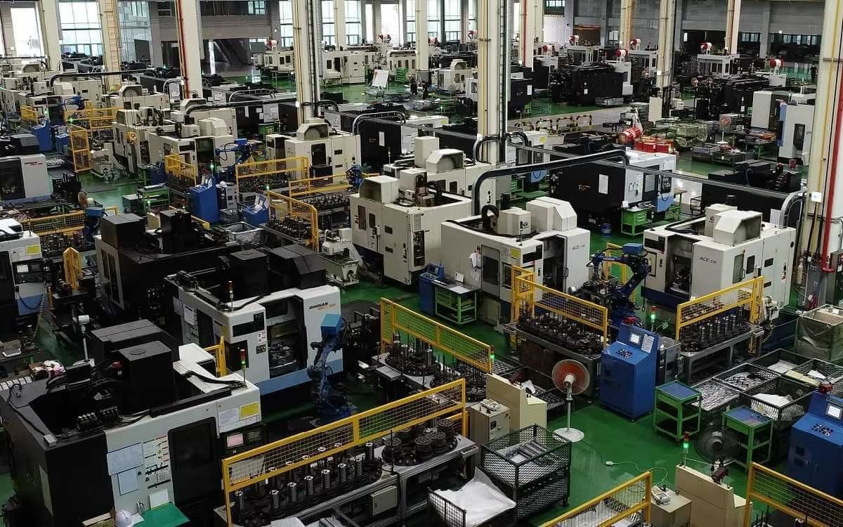
Company Profile


Frequently Asked Questions
1.What ls our Main Products?
1.Hydraulic pump
2.Hydraulic valve
3.Hydraulic motor
4.Hydraulic cylinder
5.Hydraulic parts
2. What about the MOQ?
3.What are your advantages?
- Adhere to quality first.
- Support customization, ODM & OEM service.
- 1-year warranty and complete after-sales support.
- Safe and fast shipping worldwide.
- 24-hour online service for your inquiries.
4.Are you a manufacturer? What’s your delivery time?
Yes, we are a manufacturer with our own factory.
Common models are in stock, and orders are usually shipped within 1–3 days.
5.Which payment methods are accepted?
We accept T/T, L/C, PayPal, VISA, Western Union, Apple Pay, Google Pay, Afterpay (Clearpay), Klarna, and Trade Assurance.
For full orders: 30% deposit, balance before shipment.
For small/sample orders: full payment in advance.
6.How will you deliver my goods?
We offer flexible shipping options: DHL, UPS, FedEx, TNT, EMS, as well as air or sea freight.
All deliveries ensure door-to-door fast and safe service.
7.How do you inspect and guarantee your products?
All products are tested before shipment to ensure perfect working condition.
We offer a 12-month warranty — if a product fails due to quality issues, we provide free spare parts or repair support.
8.What about after-sales service?
If you encounter any problem during use, please contact your sales manager or our support team at any time.
We will respond quickly and help solve the issue efficiently.
9.What are your main applications?
- Hydraulic systems
- Agricultural machinery
- Construction machinery
- Automobile industry
- Local distributors and maintenance centers
10.Can I get a discount for bulk orders?
Yes. We offer competitive wholesale prices and try our best to give benefits to long-term partners.
Shoot Us An Email
Professional Manufacturer