
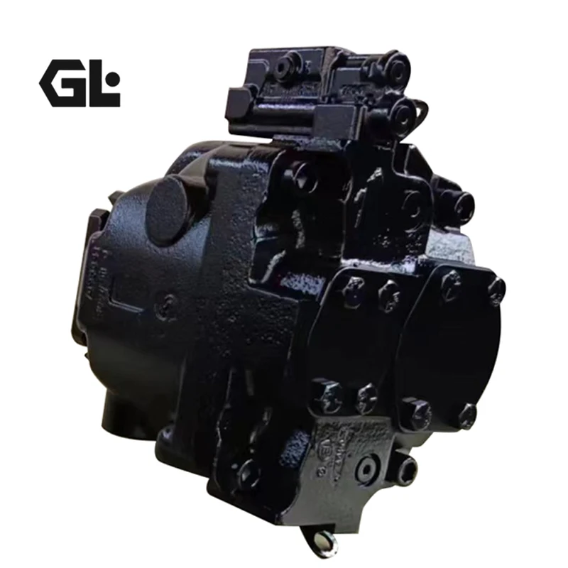
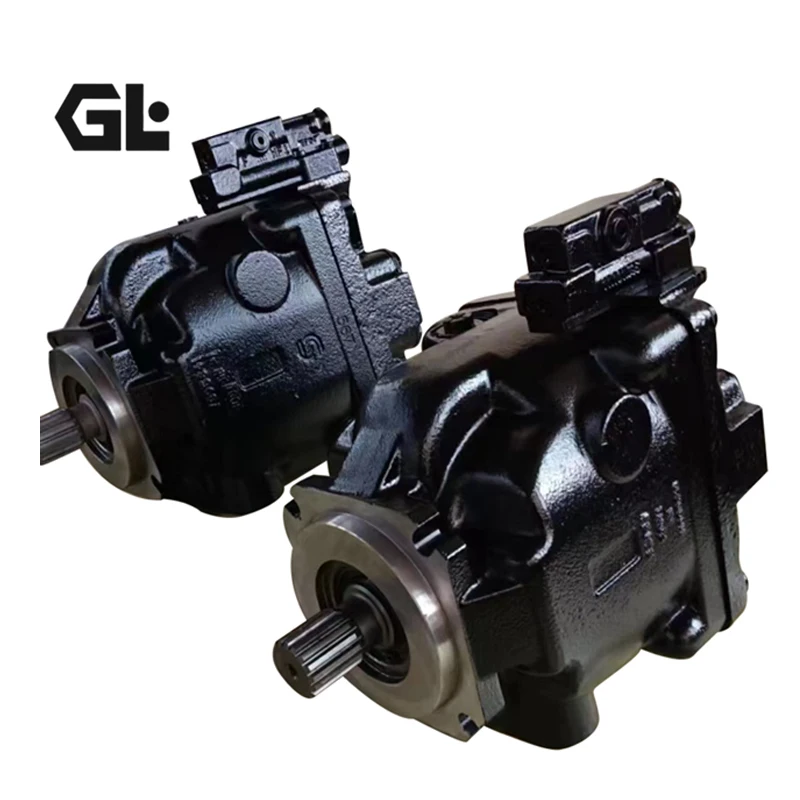
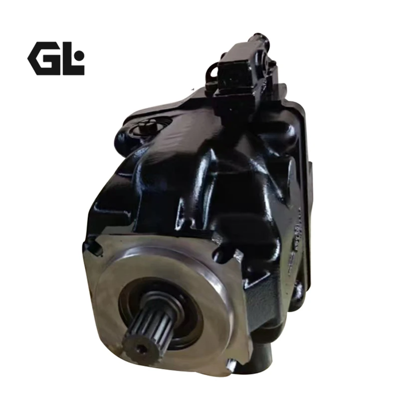
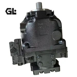
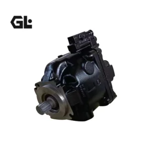
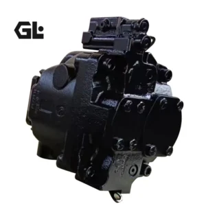
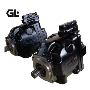
Product Overview
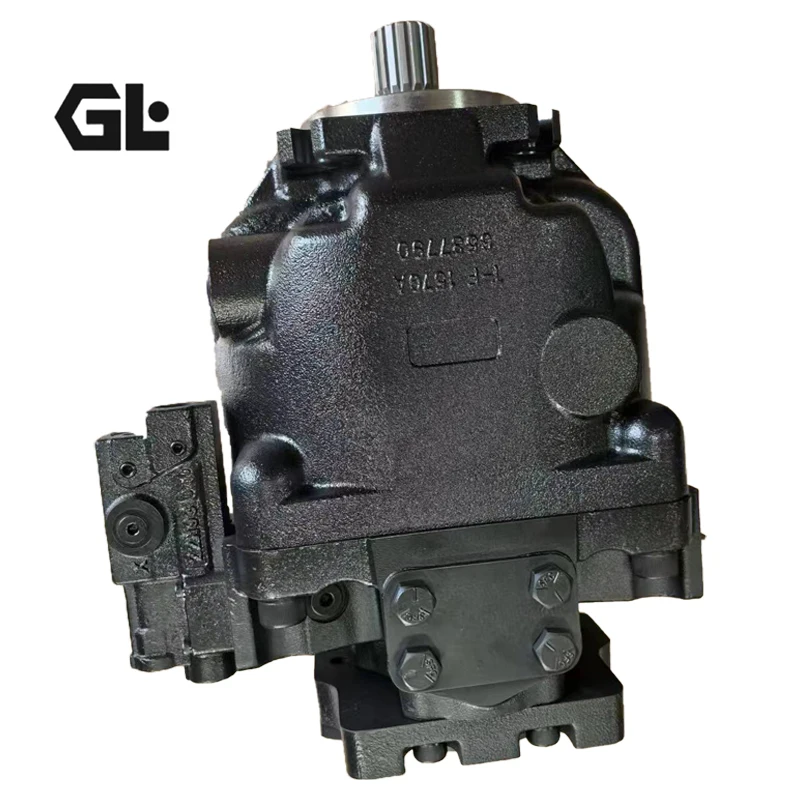
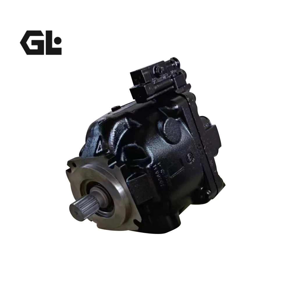
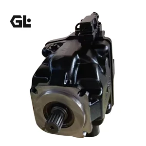
The ERR100B and ERL100B are core models within the Danfoss (formerly Sauer Danfoss) Series 45 (S45) family of open-circuit axial piston variable displacement pumps, Frame E (100 cc class). The Series 45 platform spans displacements from 25 to 147 cm³/rev, with continuous working pressures up to 310 bar and maximum speeds up to 3,600 rpm, serving as Danfoss’s flagship product family in the mobile hydraulics segment.
The Series 45 is renowned for its compact lightweight design, flexible integrated control options, and excellent power density, with extensive field-proven applications in wheel loaders, forklifts, excavators, telehandlers, and forestry machinery. The series is produced in North America, Europe, and Asia, with each frame uniquely designed to optimize performance, size, and cost.
Model Code Breakdown:
Using ER-R-100B-LS-25-20-NN-N-3-S1RP-A1N-AAA-NNN-NNN as example:
ER: Series 45 open-circuit axial piston variable pump (Frame E)
R / L: Rotation direction. R = right-hand (clockwise, viewed from shaft end); L = left-hand (counterclockwise). ERR = right-hand configuration; ERL = left-hand configuration
100B: Nominal size, geometric displacement 100 cm³/rev
LS: Load Sensing control — automatically adjusts pump displacement by sensing the pressure differential across a throttle valve, delivering flow on demand
25: Pressure compensator (PC) setting code
20: LS stand-by differential pressure setting of 20 bar. Danfoss technical literature recommends a 20 bar LS setting as a starting point for all new applications
NN-N: Additional control/interface codes
3: Design series number
S1RP / S1BP / K5NL: Shaft, port, and auxiliary mounting configuration codes
Configuration Analysis of Covered Models:
ERR100BLS2520NNN3K5NLA1NNNNNNNNNN: Right-hand rotation, 100 cc/rev, LS control, PC setting 25, LS stand-by 20 bar, K5NL shaft/port configuration
ERR130BLS2230NNN3S1BPA1NNNNNNNNNN: Right-hand rotation, 130 cc/rev, LS control, PC setting 22, LS stand-by 30 bar, S1BP shaft/port configuration. S1BP corresponds to 14-tooth 12/24 pitch splined shaft, SAE-B 13-tooth auxiliary drive, radial ports, 4-bolt inlet port.
ERR100BLS2520NNN3S1BPA1NNNNNNNNNN: Right-hand rotation, 100 cc/rev, LS control, PC setting 25, LS stand-by 20 bar, S1BP configuration
Drop-in Replacement Advantage: Manufactured to exact Danfoss OEM specifications, these pumps achieve complete drop-in interchangeability with the original Series 45 Frame E for SAE-C 4-hole mounting flange, splined shaft (ANSI B92.1), port layout, and LS control interface. Every pump undergoes 100% simulated load testing prior to shipment, validating 310 bar pressure loading, LS response characteristics, and volumetric efficiency under conditions replicating real-world duty cycles.
Technical Specifications
ERR100B (E100B) Series General Specifications:
Series: Danfoss Series 45 Frame E (Open Circuit, Swashplate Design)
Nominal Size: E100B
Geometric Displacement: 100 cm³/rev (6.10 in³/rev)
Continuous Working Pressure: 310 bar (4495 psi)
Peak Pressure: 400 bar (5800 psi)
Continuous Maximum Speed: 2450 rpm
Maximum Speed: 2880 rpm
Minimum Speed: 500 rpm
Theoretical Flow at Rated Speed: 245 L/min (64.7 GPM)
Mounting Flange: SAE-C 4-bolt
Shaft: ANSI B92.1 splined shaft
Control Type: Load Sensing (LS) with integrated pressure compensator
PC Pressure Setting Range: 100–280 bar
LS Differential Pressure Setting Range: 10–40 bar
Housing Material: Cast Iron
Weight: Approx. 52 kg
ERR130B (E130B) Series General Specifications:
Series: Danfoss Series 45 Frame E (Open Circuit, Swashplate Design)
Nominal Size: E130B
Geometric Displacement: 130 cm³/rev (7.93 in³/rev)
Continuous Working Pressure: 310 bar (4495 psi)
Peak Pressure: 400 bar (5800 psi)
Continuous Maximum Speed: 2200 rpm
Maximum Speed: 2600 rpm
Minimum Speed: 500 rpm
Theoretical Flow at Rated Speed: 286 L/min (75.5 GPM)
Mounting Flange: SAE-C 4-bolt
Shaft: ANSI B92.1 splined shaft
Control Type: Load Sensing (LS) with integrated pressure compensator
PC Pressure Setting Range: 100–280 bar
LS Differential Pressure Setting Range: 10–40 bar
Housing Material: Cast Iron
Weight: Approx. 55 kg
Series 45 Frame E Displacement Size Reference:
E100B: 100 cm³/rev, continuous pressure 310 bar, continuous speed 2450 rpm, theoretical flow 245 L/min, SAE-C flange
E130B: 130 cm³/rev, continuous pressure 310 bar, continuous speed 2200 rpm, theoretical flow 286 L/min, SAE-C flange
E147C: 147 cm³/rev, continuous pressure 260 bar, continuous speed 2100 rpm, theoretical flow 308.7 L/min, SAE-C flange
Key Technical Advantages
1. Load Sensing Control with On-Demand Flow
The Series 45 Frame E’s core control method is load sensing (LS) with integrated pressure compensator (PC). The LS controller senses the pressure differential (Δp) across a throttle valve installed in the user line and automatically adjusts pump displacement to maintain constant throttle pressure drop, delivering precise flow on demand. The system delivers only the flow actually required by the actuators, avoiding excess flow being converted to heat through the relief valve for significant energy savings under variable load conditions. PC pressure setting range is 100–280 bar, and LS differential pressure setting range is 10–40 bar. LS stand-by settings (e.g., 20 bar or 25 bar) can be matched to the system throttle valve characteristics.
2. SAE-C 4-Bolt Mounting Flange with Standardized Interfaces
The entire Series 45 Frame E range uses the SAE-C 4-bolt mounting flange with dimensions per SAE J744 standard. The shaft is an ANSI B92.1 standard splined shaft; S1BP configuration corresponds to a 14-tooth 12/24 pitch splined shaft, while K5NL configuration corresponds to a different spline specification. The standardized mounting interface and radial port layout require no adaptation for replacement, significantly reducing equipment downtime.
3. Compact Lightweight Design with High Power Density
The Series 45 Frame E is renowned for its compact lightweight design, particularly suitable for space-constrained mobile equipment. The E100B achieves 100 cm³/rev with a weight of approximately 52 kg; the E130B achieves 130 cm³/rev with a weight of approximately 55 kg, leading its displacement class in power density. The compact axial dimensions make the Series 45 particularly suitable for wheel loaders, forklifts, and other mobile hydraulic applications with strict installation space requirements.
4. Cast-Iron Housing with Wide Temperature Adaptability
The pump body is precision-cast from high-strength cast iron, with the material’s damping characteristics effectively suppressing structural vibration and fluid-borne noise. The wide operating temperature range accommodates intermittent maximum temperatures up to +104°C, continuous maximum +82°C, and minimum -40°C, particularly suitable for mobile hydraulic equipment operating outdoors and in harsh conditions. Cast iron’s lower thermal expansion coefficient helps maintain stable clearances in internal running pairs, extending service life.
5. Flexible Integrated Control Options with Factory Pre-Setting
The Series 45 supports multiple control options: load sensing (LS), pressure compensating (PC), electric displacement control (EDC), fan drive control (FDC), and electronic torque limiting (ETL), customizable for different application requirements. LS control can be configured with different PC pressure settings and LS differential pressure settings, with integrated adjustable displacement limiter. Factory pre-set pressures (e.g., DA 200 bar, LS stand-by 20 bar) allow immediate operation upon installation.
Application Areas
Wheel Loaders: Work equipment hydraulic systems, steering hydraulic circuits
Forklifts: Lift, tilt, and attachment hydraulic systems
Telehandlers: Boom extend and lift hydraulic circuits
Forestry Machinery: Forestry forwarders and harvesters hydraulic systems
Agricultural Machinery: Combine harvester hydraulic drives, sprayer hydraulic systems
Material Handling: Reach stackers, container handler hydraulic systems
Screening & Crushing Equipment: Mobile screeners, crusher hydraulic drives
Expert Maintenance Tips
1. Hydraulic Fluid Cleanliness
The Series 45 LS control spool operates with extremely tight clearances and is highly sensitive to particulate contamination. System fluid cleanliness must meet ISO 4406 22/18/13 or better. Install a 10 μm absolute-rated filter element at the pump inlet. Replace elements at 500 hours after first commissioning, then every 1,000 operating hours or 6 months, whichever comes first. Contamination control is the primary condition for ensuring long-term stable LS controller operation.
2. LS Controller Commissioning and Differential Pressure Setting
The LS controller has a PC pressure setting range of 100–280 bar and an LS differential pressure setting range of 10–40 bar. The LS stand-by differential pressure setting (20 bar or 25 bar) must be matched to the system throttle valve characteristics. Danfoss technical literature recommends a 20 bar LS setting as a starting point for all new applications; for fan-drive systems and systems with motors, the LS setting should be no less than 15 bar to enhance system stability.Adjust only with the system at zero load. Rotate the adjustment screw slowly and verify stable pressure gauge readings before proceeding.
3. Case Drain Line Requirements
The case drain line must return directly to the reservoir. Maximum permissible back pressure is 2 bar (0.2 MPa). The drain outlet must terminate below oil level at all times to prevent air ingestion. The drain line diameter must not be smaller than the pump case drain port size. For “drive shaft upwards” installation positions, filling and air bleeding must be performed completely.
4. Pre-Start Priming and Air Bleeding
Before first start, fill the pump housing with clean hydraulic fluid through the case drain port. After installation, turn the drive shaft by hand several revolutions to confirm free rotation without binding. Position the control at neutral (zero displacement) and run at low speed for 5–10 minutes. Verify continuous bubble-free flow from the case drain. Only then apply load.
5. Splined Shaft and Coupling Maintenance
The Series 45 Frame E uses ANSI B92.1 standard splined shafts. Ensure drive shaft alignment during installation, employing a flexible coupling. Apply appropriate grease to the spline connection to prevent fretting wear. Inspect coupling alignment and spline wear at 500 hours after first commissioning, then recheck every 2,000 operating hours.