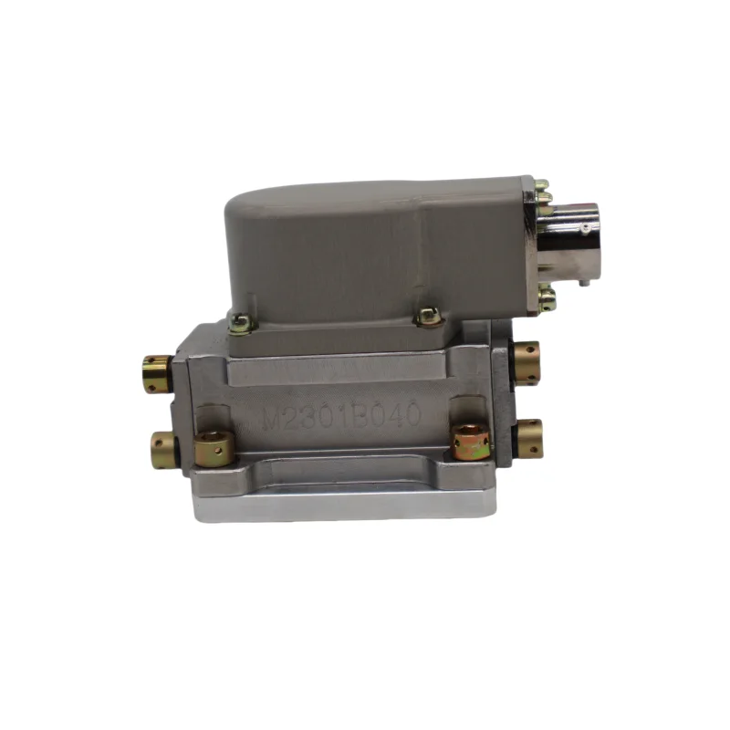
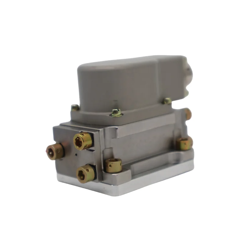
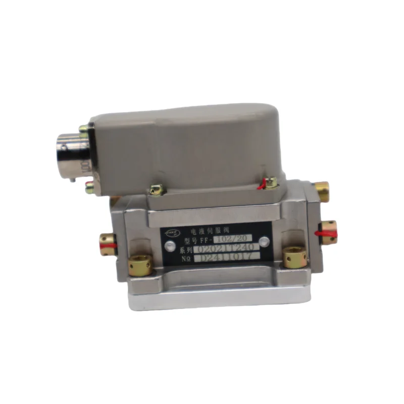
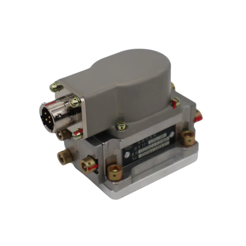
Product Overview
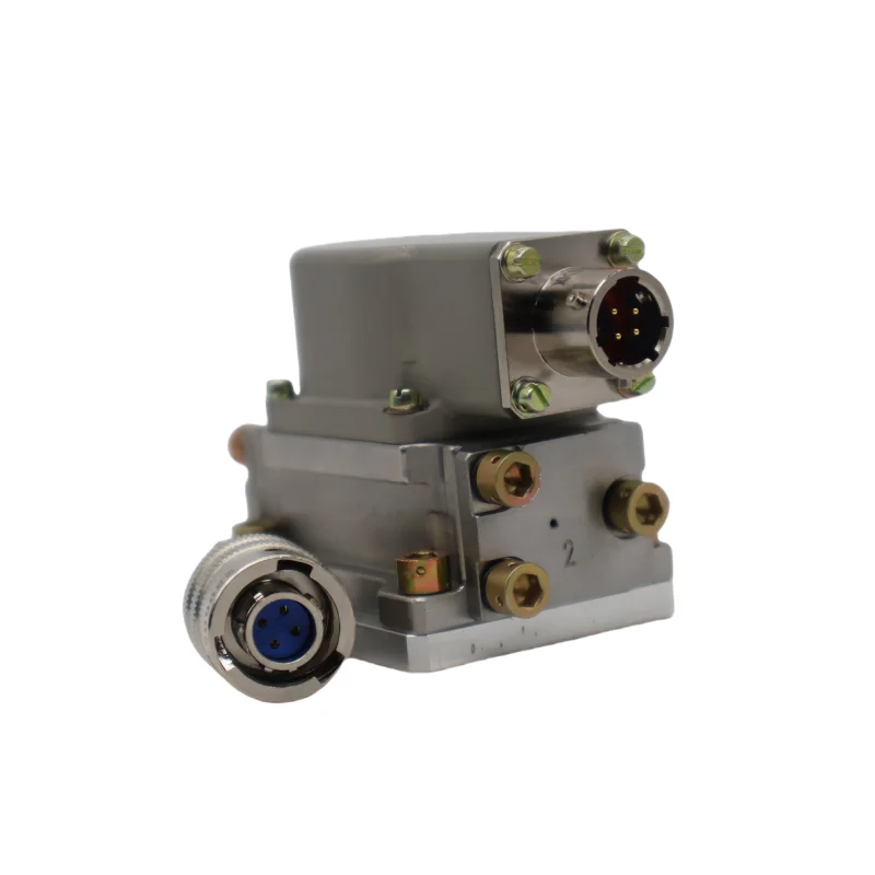
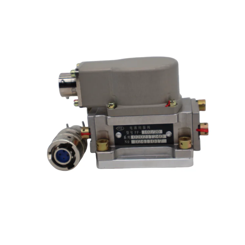
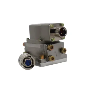
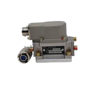
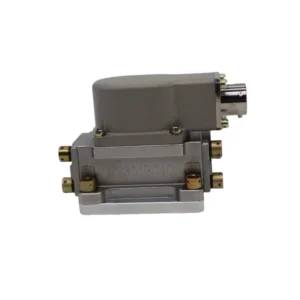
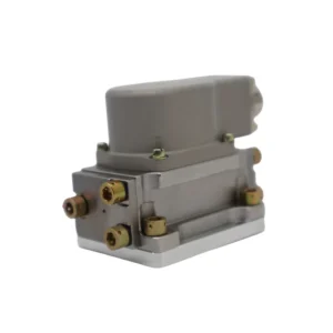
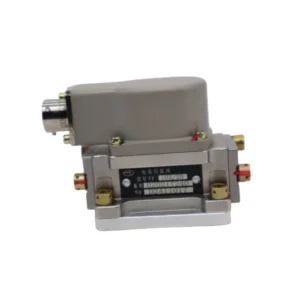
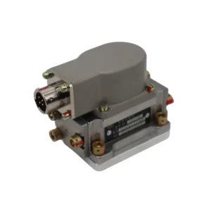
The FF-102/30 is the highest-flow variant within the FF-102 series of force feedback two-stage dual-nozzle flapper flow servo valves, developed by the AVIC 609th Research Institute (Nanjing Electro-Hydraulic Engineering Research Center). The series operates under a pressure difference of 21MPa with a flow range of 2 to 30 L/min. It adopts an all-stainless steel housing with a compact internal structure, high structural strength, and relatively small volume and weight. The installation direction of the plug and socket can be selected according to requirements. It has advantages including fast dynamic response, good linearity, small zero drift, stable working performance, high reliability, long service life, small internal leakage, and low power consumption, suitable for small and medium-sized rolling mills, blow molding machines, and test equipment.
The core function of the FF-102/30 is to convert electrical command signals into proportional hydraulic flow output. The valve employs a dual-nozzle flapper force feedback architecture, with a symmetrical double-nozzle flapper pilot stage and a four-way sliding spool power stage, achieving mechanical force feedback closed-loop spool position control through a feedback spring. Under a pressure difference of 21MPa, the FF-102/30 delivers a rated flow of 30 L/min. The supply pressure range is 2–28 MPa with a rated supply pressure of 21 MPa.
The FF series encompasses multiple servo valve product lines: FF-101 is a small-flow force feedback servo valve with rated flow of 1–8 L/min; FF-102 is a medium-flow force feedback servo valve with rated flow of 2–30 L/min; FF-106/FF-106A are large-flow force feedback servo valves with rated flow of 63/100 L/min; FF-113 is a 95/150 L/min large-flow servo valve; FF-130/FF-131 are force feedback two-stage dual-nozzle flapper servo valves; FF-133 is a linear direct drive servo valve; FF-701 is an electric feedback dual-nozzle flapper large-flow servo valve.
The FF-102/30 is fully interchangeable with the Moog 31 (D061 series) in terms of technical data and dimensions, serving as a domestic replacement for imported servo valves. Every unit undergoes 100% simulation-based testing prior to shipment, covering null stability, flow linearity, pressure gain, internal leakage, and step response.
Technical Specifications
All parameters below are based on AVIC 609th Research Institute official technical documentation and verified supplier technical pages:
FF-102/30 Technical Specifications:
Complete Model: FF-102/30
Product Series: FF-102 series force feedback two-stage dual-nozzle flapper flow servo valve
Manufacturer: AVIC 609th Research Institute (Nanjing Electro-Hydraulic Engineering Research Center)
Spool Function: Force feedback two-stage dual-nozzle flapper flow servo valve, four-way sliding spool power stage
Rated Supply Pressure Ps: 21 MPa (210 bar / 3050 psi)
Supply Pressure Range: 2 – 28 MPa
Rated Flow Qn (ΔP_N = 21 MPa): 30 L/min
Rated Current In: 10 mA or 40 mA (depending on coil configuration)
Coil Resistance: 50 Ω / 700 Ω (for 40 mA / 10 mA configuration)
Hysteresis: ≤ 4%
Resolution: ≤ 1%
Non-linearity: ≤ ±7.5%
Unsymmetry: ≤ ±10%
Pressure Gain: > 30% Ps / 1% In
Internal Leakage: ≤ 0.5 + 4% Qn (i.e. ≤ 1.7 L/min for 30 L/min variant)
Null Bias: ≤ ±3%
Null Shift with Supply Pressure (80%~110% Ps): ≤ ±2%
Null Shift with Return Pressure (0~20% Ps): ≤ ±2%
Temperature Null Shift: ≤ ±4% (-30~+150°C)
Frequency Response (Amplitude -3dB): ≥ 100 Hz
Phase Frequency (-90°): ≥ 100 Hz
Operating Temperature Range: -55°C to +150°C
Net Weight: Approx. 0.4 kg
Housing Material: All-stainless steel
Working Medium: YH-10, YH-12 aviation hydraulic oil
Coil Connection Modes: Differential, parallel, or individual coils; series configuration also available
Dither Current: 10~20% In
Dither Frequency: 100~400 Hz
FF-101 Series Technical Specifications:
Rated Flow Qn: 1, 1.5, 2, 4, 6, 8 L/min
Rated Current In: 10 mA or 40 mA
Rated Supply Pressure Ps: 21 MPa
Hysteresis: ≤ 4%
Resolution: ≤ 1%
Weight: 0.19 kg
FF-106/FF-106A Series Technical Specifications:
Rated Flow Qn: 63 / 100 L/min
Rated Current In: 15 / 40 mA
Coil Resistance: 200 / 80 Ω
Rated Supply Pressure Ps: 21 MPa
Hysteresis: ≤ 4%
Resolution: ≤ 0.5% (FF-106-103/FF106A specific variants)
Weight: 1 kg (FF-106 basic type)
Note: Specifications are based on AVIC 609th Research Institute official technical documentation and verified supplier technical pages. The FF-102 series offers six rated flow specifications: 2, 5, 10, 15, 20, and 30 L/min. The series is fully interchangeable with Moog 31 in terms of technical data and dimensions. Customized services are available for special current, flow, weight, and working medium requirements.
Key Technical Advantages
1. Force Feedback Closed-Loop Control Architecture with High Precision and Fast Dynamic Response
The FF-102/30 employs a force feedback two-stage dual-nozzle flapper architecture. When an electrical command signal is applied to the torque motor coils, the flapper deflects between two nozzles, creating a differential pressure across the spool ends that drives spool displacement. Spool movement applies force through a feedback spring to the torque motor armature assembly, establishing a mechanical force feedback closed loop. This architecture does not rely on electronic displacement sensors, offering exceptional immunity to electromagnetic interference and long-term stability. Both amplitude frequency response and phase frequency response are no less than 100 Hz, delivering rapid dynamic response for high-frequency dynamic loading and rapid switching control requirements.
2. All-Stainless Steel Housing with Wide Temperature Range for Demanding Environments
The FF-102/30 features an all-stainless steel housing with a compact internal structure, high structural strength, and relatively small volume and weight (net weight approx. 0.4 kg). The stainless steel housing provides excellent corrosion resistance and wide temperature adaptability, with an operating temperature range covering -55°C to +150°C, suitable for aviation, aerospace, and industrial systems with demanding environmental conditions and high reliability requirements.
3. Low Null Drift and Low Internal Leakage Design
The valve achieves supply pressure null shift of no more than ±2% (80%~110% Ps), return pressure null shift of no more than ±2% (0~20% Ps), and temperature null shift of no more than ±4%, ensuring stable null output under varying pressure and temperature conditions. Internal leakage is limited to ≤ 0.5 + 4% Qn (approximately ≤ 1.7 L/min for the 30 L/min variant), effectively conserving energy and maintaining control accuracy.
4. Moog 31 Drop-In Interchangeability with Versatile Coil Configuration
The FF-102/30 is fully interchangeable with the Moog 31 (D061 series) in terms of technical data and dimensions, enabling direct replacement of imported servo valves without hydraulic circuit or control wiring modification. The valve supports differential, parallel, or individual coil connection modes, with rated current options of 10 mA or 40 mA and corresponding coil resistances of 700 Ω and 50 Ω, facilitating flexible selection based on existing controller configurations. The plug and socket installation direction can be selected according to requirements, facilitating wiring in compact installation spaces.
5. 100% Simulation-Based Testing and Drop-In Interchangeability
Every FF-102/30 undergoes 100% simulation-based testing prior to shipment. Test protocols cover rated flow calibration, hysteresis and linearity measurement, pressure gain verification, and internal leakage detection. As a drop-in replacement, the valve is fully compatible with the OEM Moog 31 specification in mounting dimensions, electrical connection, and performance characteristics, enabling direct replacement of the original valve.
Application Areas
Small and Medium-Sized Rolling Mills: Precision position and pressure closed-loop control for rolling mill hydraulic gap systems
Blow Molding Machines: Parison wall thickness control and mold clamping pressure regulation
Test Equipment: Precision flow control for electro-hydraulic servo loading systems
Aviation Hydraulic Systems: Electro-hydraulic servo control of flight control surface actuators
Aerospace Hydraulic Systems: Precision control of spacecraft hydraulic drive mechanisms
Material Testing Systems: Loading control for electro-hydraulic servo fatigue test rigs
Industrial Automation Lines: Integration with PLC and motion controllers for precision position, velocity, or force control
Steel & Metallurgy Equipment: Continuous casting mold level control, rolling mill AGC systems
Expert Maintenance Tips
Pre-Installation Checks:
Verify mounting surface dimensions are compatible with the Moog 31 interface; flatness deviation not exceeding 0.01 mm/100 mm, surface roughness Ra ≤ 0.8 μm
Flush all piping with clean hydraulic fluid prior to installation; ensure system cleanliness meets servo valve requirements
Inspect O-ring seals for damage and confirm compatibility with the hydraulic fluid in use
Verify electrical connector (plug and socket) contact integrity; confirm coil wiring mode (differential/parallel/individual) matches the controller
Operational Maintenance:
Use precision pressure filters matched to the servo valve (≤ 10 μm absolute filtration recommended); replace filter elements at regular intervals
Recommended working medium: YH-10, YH-12 aviation hydraulic oil; maintain operating temperature within -55°C to +150°C
Maintain supply pressure within 2 – 28 MPa range; rated supply pressure is 21 MPa
Periodically verify coil resistance remains within rated range (700 Ω or 50 Ω)
System return back pressure must not exceed 20% Ps to avoid excessive back pressure causing null offset
Periodically monitor internal leakage; FF-102/30 specification internal leakage should be ≤ 1.7 L/min
Troubleshooting Guide:
Spool fails to actuate or responds abnormally: Check command signal reaches the coil (rated current 10 mA or 40 mA), measure coil resistance against 700 Ω or 50 Ω range, confirm plug and socket engagement is reliable
Null-point drift: After ruling out fluid contamination, inspect feedback spring for fatigue or deformation; verify pilot stage nozzle-flapper clearance has not changed due to wear
Insufficient flow: Confirm system supply pressure is within the 2 – 28 MPa allowable range; check spool metering edges for partial blockage by contaminant particles
Increased internal leakage: Check system cleanliness level; inspect spool/sleeve for wear; replace seals if necessary
Slow response: Check system cleanliness level; verify pilot stage nozzles are not partially blocked by contaminant particles