


H1B110AAL2BANAPBDSKSBA10NPMB0N00NNN Danfoss H1B110 Bent Axis Motor 110cc
| Model Number | H1B110AAL2BANAPBDSKSBA10NPMB0N00NNN |
|---|
Product Description
Product Overview
The H1B110AAL2BANAPBDSKSBA10NPMB0N00NNN belongs to the Danfoss (formerly Sauer Danfoss) H1B Series bent-axis axial piston variable displacement motor family, frame size 110, with a maximum displacement of 110 cc/rev. The H1B series covers displacements from 60 to 250 cc/rev (H1B060/080/110/160/210/250), featuring a bent-axis design for closed-circuit hydrostatic transmission systems, delivering high power density and precise speed-torque control in travel drive and rotary drive applications.
The H1B110 is rated at 450 bar (6527 psi) continuous working pressure with a maximum peak pressure of 480 bar (6962 psi) and a maximum flow of 407 L/min. The bent-axis rotary group design provides high starting torque at maximum displacement and high speed output at minimum displacement, with displacement infinitely adjustable between the minimum setting and maximum value. The H1B motor integrates a loop flushing shuttle spool and loop flushing relief valve, ensuring oil cooling and contaminant removal in closed-circuit systems.
The H1B110AAL2BANAPBDSKSBA10NPMB0N00NNN is a complete model code where H1B110 indicates the H1B series frame size 110 motor, A indicates product version A, A indicates port configuration, L2 is the control type code, and subsequent characters correspond to pressure compensator override, endcap type, flange housing, drive shaft, speed sensor, loop flushing, minimum displacement setting, and pressure setting. The mounting flange, drive shaft spline, and port layout are identical to the original Danfoss H1B110 motor, enabling direct replacement without system modification or adapter plates.
Every motor undergoes 100% simulated operating-condition testing before shipment, including rated pressure hold, displacement regulation verification, and control response validation—delivering immediate reliability upon installation.
Technical Specifications
Model Identification:
H1B110AAL2BANAPBDSKSBA10NPMB0N00NNN — Complete model code, H1B series bent-axis variable motor, frame size 110, maximum displacement 110 cc/rev
Model code breakdown: H1B110=series/frame size, A=product version A, A=port configuration (inch per ISO 11926-1), L2=control type (hydraulic two-position, 24V DC or hydraulic), BA=endcap type, N=orifice configuration, AP=pressure compensator override and brake pressure defeat, B=0.8mm orifice diameter, DS=DIN-flange motor housing (ISO 3019/2) with speed sensor port, KS=27 tooth 16/32 pitch ANSI 92.1 1970 class 5 splined shaft with speed ring, S=speed sensor (Deutsch DTM 04-6P, 4.5-8V), A=loop flushing shuttle (6.5 bar shuttle shift pressure), 10=loop flushing relief valve (10 L/min, non-adjustable, 16 bar cracking pressure), NP=special hardware features, MB=minimum displacement setting, 0=100% maximum displacement, N=pressure compensator override setting, 00=paint and nametag
Displacement (H1B Full Series):
H1B060: 60 cc/rev
H1B080: 80 cc/rev
H1B110: 110 cc/rev (at maximum angle)
H1B160: 160 cc/rev
H1B210: 210 cc/rev
H1B250: 250 cc/rev
Pressure Ratings (H1B110):
Rated continuous working pressure: 450 bar (6527 psi)
Maximum peak pressure: 480 bar (6962 psi)
Loop flushing shuttle shift pressure: 6.5 bar
Loop flushing relief valve cracking pressure: 16 bar (232 psi)
Speed and Flow (H1B110):
Maximum flow: 407 L/min
Maximum speed (at maximum displacement): 2900 rpm (reference)
Minimum displacement setting: configured per order code, model configured with minimum displacement setting MB
Control Types:
L2 Hydraulic Two-Position Control — Displacement switched via hydraulic pilot pressure, suitable for high/low speed shifting in travel drive applications
Optional controls: electric proportional control (EDC), hydraulic proportional control, pressure compensator override, electric two-position control (E1/E2/P1/P2/T1/T2), manual control, etc.
Structural Parameters:
Motor type: Bent-axis axial piston variable displacement motor
Mounting flange: DIN flange (ISO 3019/2) with speed sensor port
Drive shaft: 27 tooth 16/32 pitch ANSI 92.1 1970 class 5 splined shaft with speed ring
Port configuration: Inch, per ISO 11926-1
Endcap type: Axial ports ISO 6162 Type 1 (metric)
Speed sensor: Deutsch DTM 04-6P connector, 4.5-8V
Housing material: Cast iron
Weight: DIN flange approx. 45.0 kg (99 lb); SAE flange approx. 48.8 kg (108 lb)
Hydraulic Fluid and Operating Conditions:
Recommended fluid: Mineral oil-based anti-wear hydraulic oil
Optimal operating viscosity range: 10-39 cSt
Operating oil temperature range: -20°C to +90°C
Cleanliness requirement: ISO 4406 18/13 or higher
Key Technical Advantages
1. Bent-Axis Design Delivers High Starting Torque and High Speed
The H1B110 features a bent-axis axial piston design with pistons arranged at an angle to the drive shaft. This configuration produces high starting torque at maximum displacement and high speed output at minimum displacement, with displacement infinitely adjustable between the minimum setting and 110 cc/rev. The hydrostatically balanced bent-axis rotary group minimizes lateral forces on the piston-cylinder interfaces, ensuring stable operation and long service life at 450 bar continuous pressure.
2. Complete Model Coding Enables 100% Drop-in Interchange
Each character in the H1B110AAL2BANAPBDSKSBA10NPMB0N00NNN corresponds to specific parameters—control type (L2 hydraulic two-position), endcap type (BA), mounting flange (DS DIN flange), drive shaft (KS 27-tooth splined shaft with speed ring), speed sensor (S), and loop flushing configuration (A shuttle + 10 relief valve). The DIN flange mounting dimensions, 27-tooth splined drive shaft, and axial port layout are identical to the original Danfoss H1B110 motor, enabling direct replacement without piping modification or adapter plates.
3. Integrated Loop Flushing System Ensures Closed-Circuit Reliability
The H1B110 integrates a loop flushing shuttle spool and loop flushing relief valve. The shuttle spool automatically separates system A and B pressures, directing low-side oil to the flushing relief valve, which discharges heat and contaminants at 10 L/min flushing flow and 16 bar cracking pressure. This design extends hydraulic fluid and component service life, reducing performance degradation caused by oil overheating.
4. High Power Density in Compact Package
The H1B110 achieves 450 bar continuous working pressure and 407 L/min maximum flow at 110 cc/rev displacement, with the DIN flange version weighing approximately 45 kg. The compact cast iron housing delivers high power density within constrained installation spaces, suitable for the tight layouts of mobile machinery travel drive systems. The efficient bent-axis rotary group minimizes internal power losses and enhances overall transmission efficiency.
5. Multiple Control Options for Diverse Travel Drive Requirements
The H1B series offers hydraulic two-position control (L2), electric two-position control (E1/E2/P1/P2/T1/T2), electric proportional control (EDC), hydraulic proportional control, and other control types, meeting the speed shifting and torque control requirements of different travel drive systems. L2 hydraulic two-position control is particularly suited for wheeled mobile machinery requiring high/low speed range shifting, enabling stepless transition between work mode and transport mode by switching motor displacement via pilot pressure.
Application Areas
Wheel loader travel drive systems (work/transport mode shifting)
Excavator travel drive and swing drive systems
Agricultural machinery (combine harvesters, tractors, sprayers) travel drive
Concrete pump trucks and mixer truck drive systems
Forklifts and material handling equipment drive systems
Municipal vehicles and sanitation equipment travel drive
Mining mobile equipment and heavy-duty engineering vehicles travel drive
Industrial rotary drive applications (injection molding machines, marine deck machinery)
Expert Maintenance Tips
1. Pre-Installation Model Verification
Verify the complete model code on the motor nameplate before installation. The H1B110AAL2BANAPBDSKSBA10NPMB0N00NNN features L2 hydraulic two-position control, DIN flange mounting (ISO 3019/2), and a 27-tooth splined drive shaft. Ensure drive shaft-to-coupling concentricity within 0.05 mm to prevent premature seal and bearing failure from radial loads. Install the motor such that the case drain port maintains oil level at or above the unit centerline.
2. Hydraulic Fluid Cleanliness Requirements
Use mineral oil-based anti-wear hydraulic oil with optimal operating viscosity range of 10-39 cSt. Fluid cleanliness should be ISO 4406 18/13 or higher. Suction filter rating should be no coarser than 10 μm. Operating oil temperature range: -20°C to +90°C. Flush the system thoroughly before first operation. In closed-circuit systems, the loop flushing valve’s 10 L/min flushing flow helps continuously clean the fluid.
3. Loop Flushing Valve Setting Check
The H1B110 integrates a loop flushing shuttle spool and loop flushing relief valve with 16 bar cracking pressure and 10 L/min flushing flow (non-adjustable). Verify the flushing valve configuration matches this model code before installation. If system cooling demand increases, select a larger flushing flow relief valve option. During system commissioning, confirm the shuttle spool shift pressure of 6.5 bar is functioning properly to ensure low-side oil effectively discharges through the flushing circuit.
4. First Start-Up Procedure
Before first start, confirm the suction line is properly sealed, the reservoir is at the correct level, and oil level is at or above the motor centerline. Run at low speed unloaded for 5-10 minutes to purge air. Confirm no suction line leakage and steady oil flow from the case drain line before gradually increasing speed and loading to rated conditions. L2 hydraulic two-position control requires a pilot pressure signal to switch displacement; confirm the pilot pressure line is correctly connected before startup.
5. Routine Maintenance
Replace hydraulic oil filters every 2,000 operating hours or annually. Periodically inspect the motor exterior for leaks and check the drive shaft spline and shaft seal for wear. If output torque decline or speed instability is observed, prioritize inspection of the piston-cylinder and valve plate wear. The loop flushing relief valve flushing flow should be periodically checked to ensure it remains at the design value of 10 L/min. Recommended overhaul interval: no more than 8,000 operating hours or 5 years. Always refer to Danfoss official H1B series technical information and parts manual during installation and service.


Company Profile

Frequently Asked Questions
1.What ls our Main Products?
1.Hydraulic pump
2.Hydraulic valve
3.Hydraulic motor
4.Hydraulic cylinder
5.Hydraulic parts
2. What about the MOQ?
3.What are your advantages?
- Adhere to quality first.
- Support customization, ODM & OEM service.
- 1-year warranty and complete after-sales support.
- Safe and fast shipping worldwide.
- 24-hour online service for your inquiries.
4.Are you a manufacturer? What’s your delivery time?
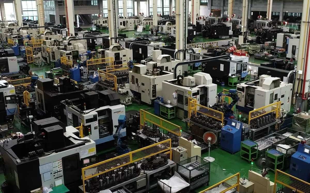
Yes, we are a manufacturer with our own factory.
Common models are in stock, and orders are usually shipped within 1–3 days.
5.Which payment methods are accepted?
We accept T/T, L/C, PayPal, VISA, Western Union, Apple Pay, Google Pay, Afterpay (Clearpay), Klarna, and Trade Assurance.
For full orders: 30% deposit, balance before shipment.
For small/sample orders: full payment in advance.
6.How will you deliver my goods?
We offer flexible shipping options: DHL, UPS, FedEx, TNT, EMS, as well as air or sea freight.
All deliveries ensure door-to-door fast and safe service.
7.How do you inspect and guarantee your products?
All products are tested before shipment to ensure perfect working condition.
We offer a 12-month warranty — if a product fails due to quality issues, we provide free spare parts or repair support.
8.What about after-sales service?
If you encounter any problem during use, please contact your sales manager or our support team at any time.
We will respond quickly and help solve the issue efficiently.
9.What are your main applications?
- Hydraulic systems
- Agricultural machinery
- Construction machinery
- Automobile industry
- Local distributors and maintenance centers
10.Can I get a discount for bulk orders?
Yes. We offer competitive wholesale prices and try our best to give benefits to long-term partners.
Shoot Us An Email
Professional Manufacturer