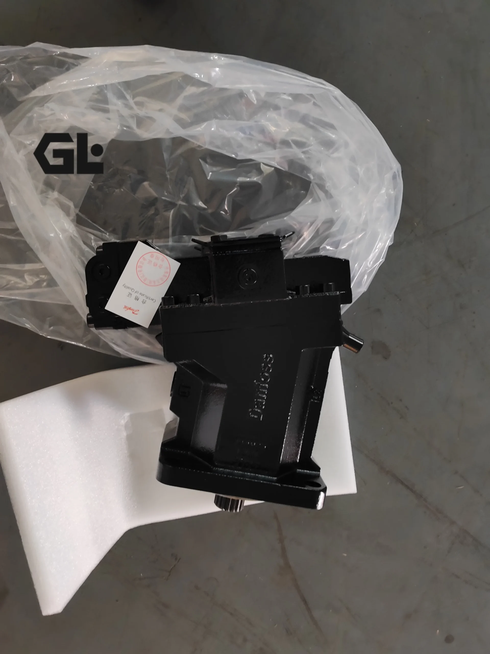
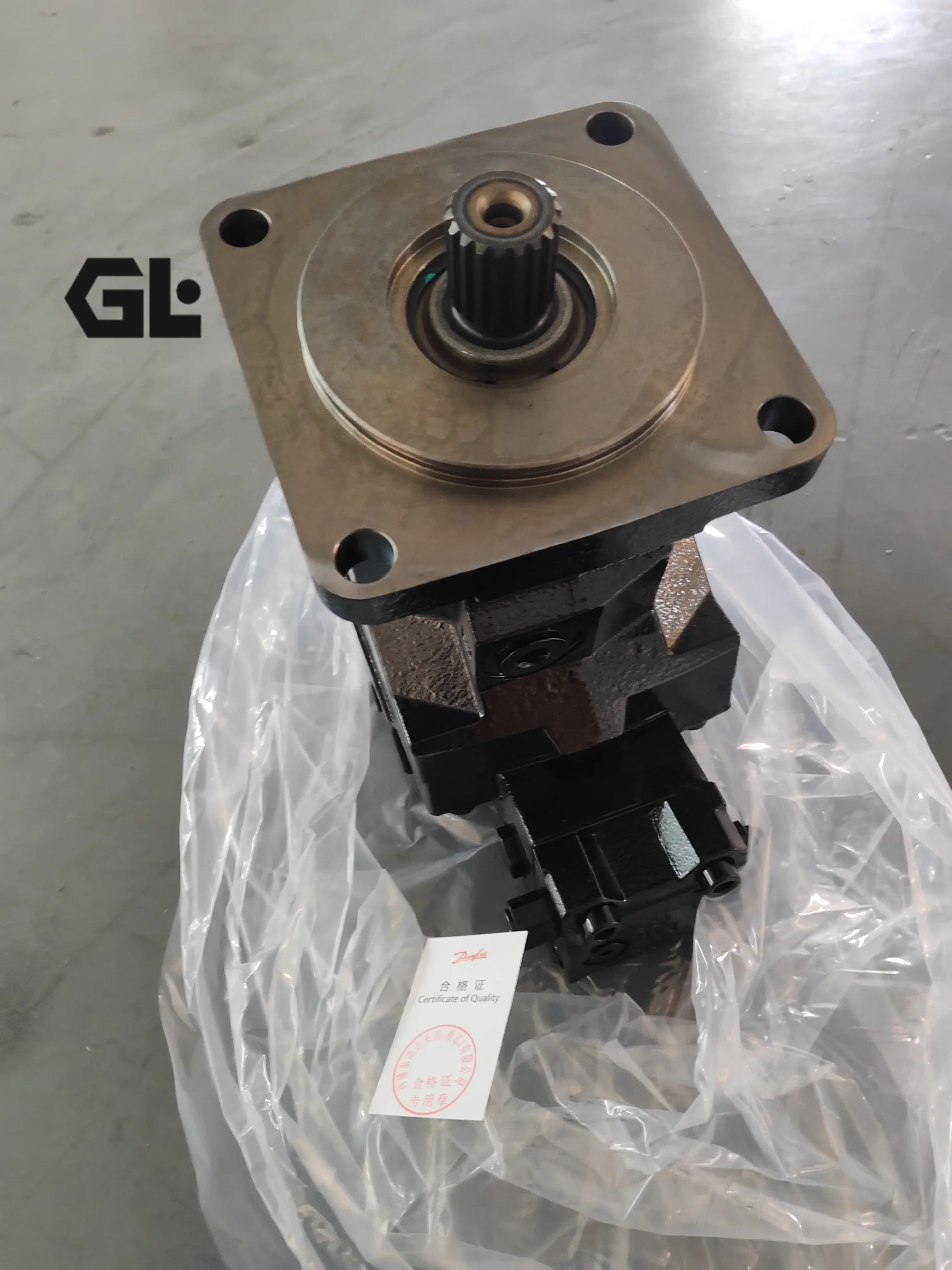
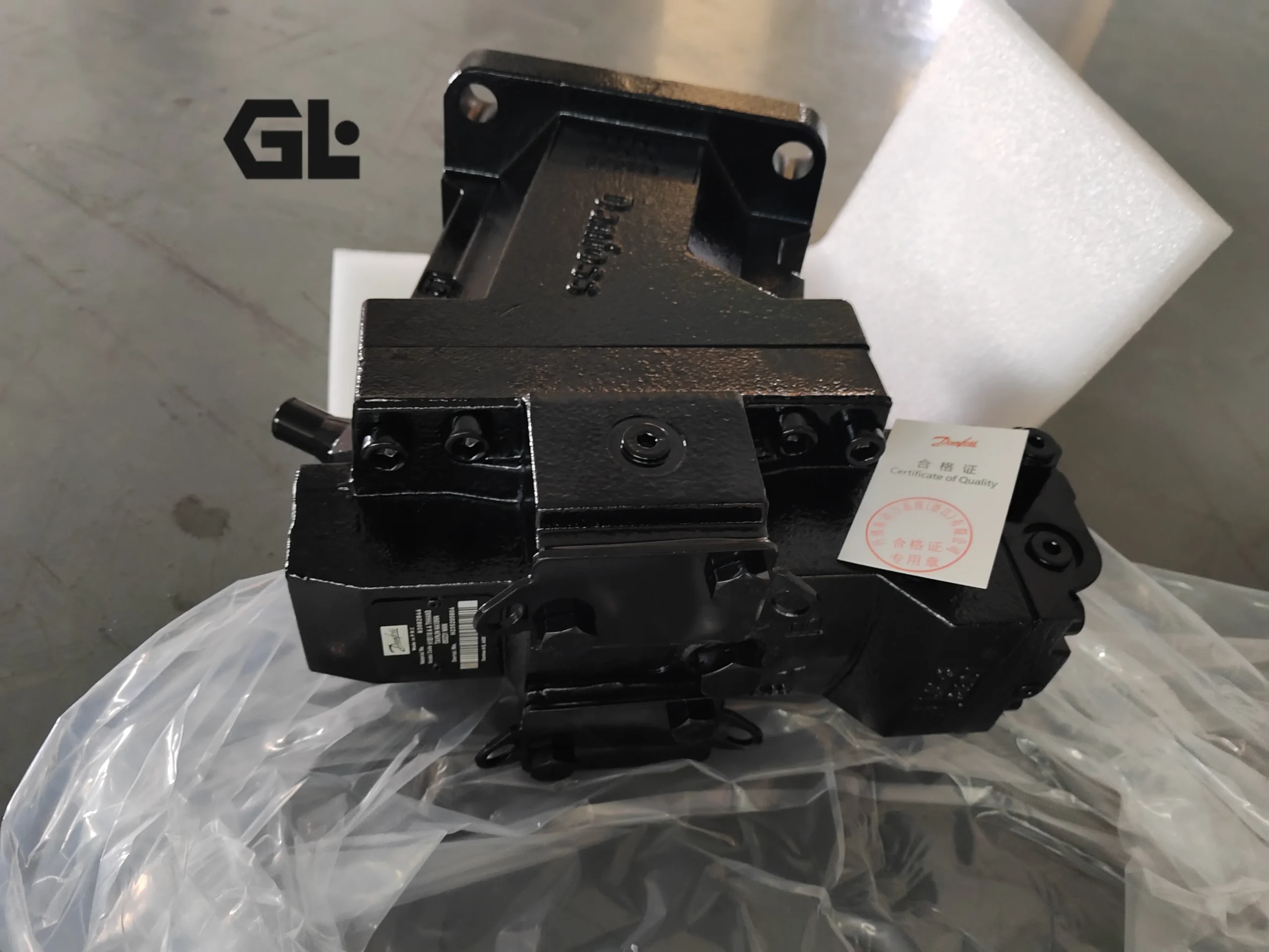
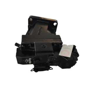
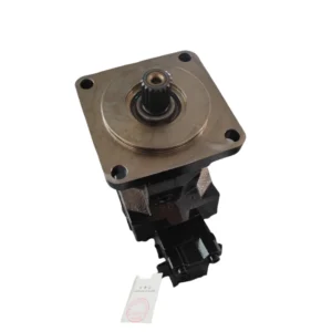

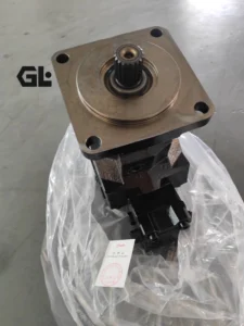
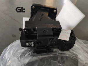
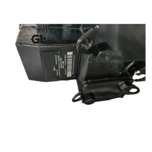
Product Overview
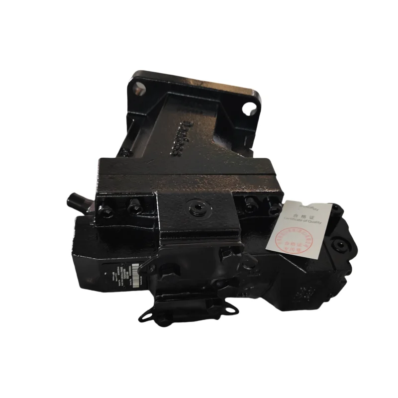
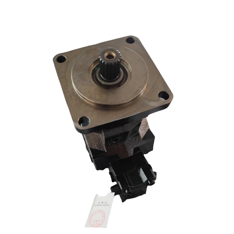
The H1B110 belongs to the Danfoss H1B Series of bent-axis axial piston variable motors, with a displacement of 110 cm³/rev, maximum working pressure of 480 bar, continuous working pressure differential of 450 bar, and maximum flow of 407 L/min. The H1B Series is the successor to the field-proven Series 51, delivering even greater robustness in a more compact package. Featuring bent-axis design with spherical pistons, the series achieves a maximum/minimum displacement ratio of 5:1, combining high output speed capability with excellent low-speed stability.
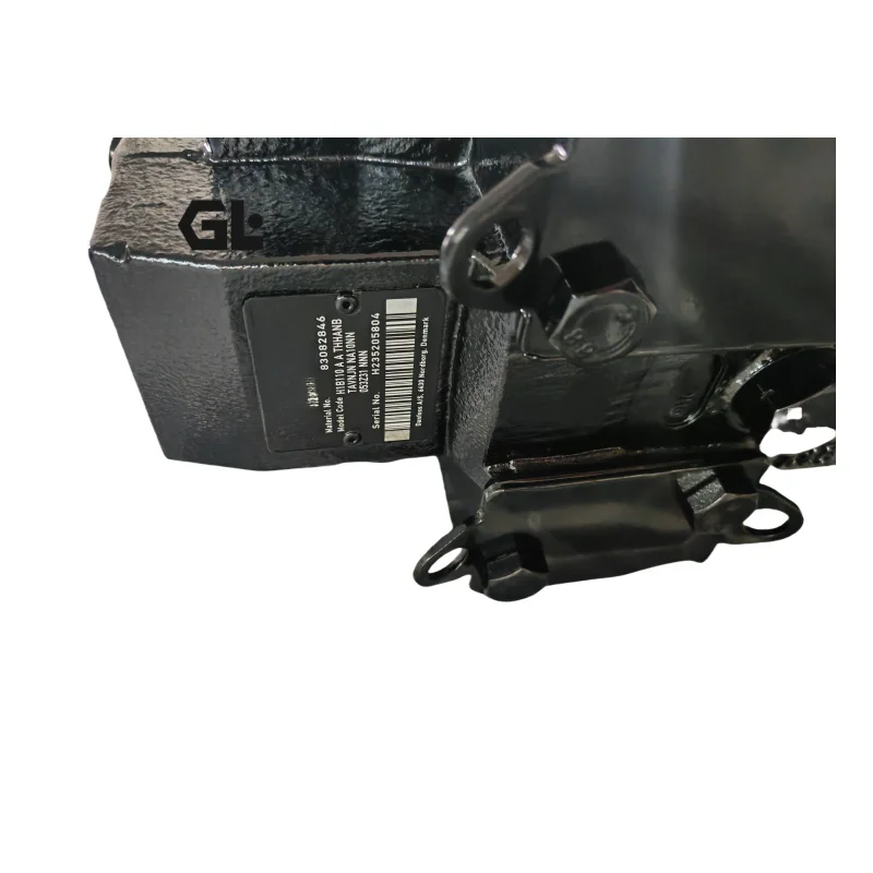
This specific model H1B110AE2AANBTBDNJNNA10NN040Z00NNN features electric two-position control (E2 control), 24V DC powered via Deutsch DT 04-2P connector, with de-energized = maximum displacement. The control configuration includes a pressure compensator override function with a setting of 250 bar, and a minimum displacement setting of 74 cm³/rev. The motor is equipped with an SAE flange housing (ISO 3019/1) with speed sensor port, a 13-tooth 8/16 pitch ANSI 92.1 1970 Class 5 spline shaft with speed ring, and an integrated speed sensor (Deutsch DTM 04-6P connector, 4.5V to 8V output). Loop flushing shuttle system is standard, with 6.5 bar shuttle shift pressure, 10 L/min flushing relief valve, and 16 bar cracking pressure.
Manufactured to original Danfoss H1B Series technical specifications with full drop-in interchangeability — no mounting flange or port connection modifications required. Every motor undergoes 100% simulated load testing at the factory, covering pressure hold, displacement control response, and flushing valve performance verification.
Technical Specifications
Series: Danfoss H1B Series
Design: Bent-axis axial piston variable motor, spherical piston design
Displacement (Maximum Angle): 110 cm³/rev
Minimum Displacement Setting: 74 cm³/rev (this configuration)
Maximum Displacement Ratio: 5:1
Maximum Working Pressure: 480 bar (6962 psi)
Continuous Working Delta Pressure (Δp): 450 bar (6527 psi)
Maximum Flow: 407 L/min
Rated Speed Range: 3,300–4,000 rpm
Speed Range: 3,300–5,300 rpm
Control Type: Electric 2-position (E2), 24V DC, Deutsch DT 04-2P connector, de-energized = maximum displacement
Pressure Compensator Override: Yes, setting 250 bar
Minimum Displacement: 74 cm³/rev (adjustable)
Maximum Displacement: 100% (non-adjustable)
Flushing System: Shuttle shift pressure 6.5 bar, relief valve 10 L/min @ 16 bar
Mounting Flange: SAE flange housing (ISO 3019/1)
Shaft Type: 13-tooth 8/16 pitch ANSI 92.1 1970 Class 5 spline
Speed Sensor: Yes, Deutsch DTM 04-6P connector, 4.5V–8V output
Weight: Approx. 48.8 kg
Housing Material: High-strength cast iron
Port Configuration: Inch, per ISO 11926-1
Model Code Interpretation (H1B110AE2AANBTBDNJNNA10NN040Z00NNN):
H1B: H1 Series bent-axis variable motor
110: Displacement code, 110 cm³/rev
A: Product version A (first version of H1B series)
A: Port configuration, inch per ISO 11926-1
E2: Electric 2-position control, 24V DC, Deutsch DT 04-2P connector, de-energized = maximum displacement
AA: Without pressure compensator override and without brake pressure defeat (Note: this model actually includes pressure compensator override — verify against nameplate)
NB: 0.8mm diameter orifices (M4 and M5)
TB: Endcap for 2-position and pressure compensator controls, side ports ISO 6162 Type 1 (metric)
DN: DIN-flange motor housing (ISO 3019/2), no speed sensor port (Note: this model actually features SAE flange and speed sensor — verify against nameplate)
JN: W40x2x30x18x9g DIN 5480 spline, no speed ring
N: No speed sensor (Note: verify against nameplate)
A: Loop flushing shuttle system, 6.5 bar shuttle shift pressure
10: 10 L/min, non-adjustable, 16 bar cracking pressure flushing relief valve
NN: Standard hardware feature, 2-position standard
040: Minimum displacement setting 40 cm³/rev
Z: 100% maximum displacement, non-adjustable
00: No pressure compensator override function
NNN: Danfoss nametag
Data based on Danfoss PowerSource official product database and H1B Series technical documentation. Due to discrepancies between certain options in the model code and the standard configurations in the Danfoss official database, users are advised to confirm against the actual product nameplate for final verification.
Key Technical Advantages
1. Bent-Axis Spherical Piston Design — High Power Density and Compact Package
The H1B Series employs bent-axis design with spherical pistons. Compared to conventional swashplate motors, spherical pistons enable greater piston stroke and more compact axial dimensions at the same displacement. The H1B110 achieves 450 bar continuous delta pressure and 480 bar peak pressure at 110 cm³/rev, weighing only approximately 48.8 kg — delivering outstanding power density among bent-axis motors in its displacement class. The H1B Series features the shortest unit length in its class, facilitating installation in space-constrained travel drive assemblies.
2. 5:1 Large Displacement Ratio — Wide Speed Range and Excellent Low-Speed Performance
The H1B110 achieves a maximum/minimum displacement ratio of 5:1, combined with electric 2-position control, enabling rapid switching between high-speed travel and low-speed high-torque operating conditions. The large displacement ratio design maintains stable low-speed operation even at minimum displacement, avoiding the stick-slip phenomenon experienced by fixed displacement motors under low-speed conditions. Rated speed range is 3,300–4,000 rpm, with speed range up to 5,300 rpm, meeting full operating condition requirements from precision work to high-speed travel.
3. Electric 2-Position Control — Fast Response and Precise Displacement Switching
This model features E2 electric 2-position control, powered by 24V DC through a Deutsch DT 04-2P connector. De-energized, the motor automatically returns to maximum displacement, ensuring a safe and reliable fail-safe mode. The pressure compensator override is set at 250 bar — when system pressure exceeds the setpoint, the motor displacement is automatically driven toward minimum to prevent system overload. This control method offers fast response, suitable for travel drive systems requiring frequent displacement state switching.
4. Integrated Flushing System and Speed Sensor
This model features standard loop flushing shuttle system with 6.5 bar shuttle shift pressure and a 10 L/min flushing relief valve to maintain system cleanliness and temperature stability. The flushing system is critical in closed-circuit applications, effectively removing heat generated inside the motor and extending fluid and seal life. The speed sensor (Deutsch DTM 04-6P connector, 4.5V–8V output) provides real-time speed feedback to the vehicle control system, supporting precise speed closed-loop control and fault diagnostics.
Application Areas
Travel Drive Systems: Combine harvester travel drive, self-propelled forage harvester travel system, forestry forwarder travel drive
Construction Machinery: Road compactor travel drive, trencher hydraulic drive, mini excavator travel system
Material Handling: Telehandler travel drive, skid steer loader hydraulic drive
Agricultural Machinery: Large tractor hydraulic drive, sprayer travel system, beet harvester hydraulic transmission
Specialty Vehicles: Snow removal truck hydraulic drive, municipal engineering vehicle travel systems
Industrial Drive: Winch hydraulic drive, hoist hydraulic systems, test bench load simulation
Expert Maintenance Tips
Pre-Installation Cleanliness Control: Before installing the H1B110 motor, verify hydraulic system cleanliness meets ISO 4406 18/16/13 or better. Port plugs should be removed and piping connected immediately after unboxing — environmental exposure should not exceed 15 minutes. Before initial installation, fill the motor case approximately half full with clean hydraulic oil. Dry-start is strictly prohibited. Ensure concentricity between the motor shaft and prime mover shaft is maintained within 0.05 mm.
E2 Control Electrical Check: E2 electric 2-position control is powered through a Deutsch DT 04-2P connector — verify 24V DC polarity is correct. De-energized, the motor should be at maximum displacement; energized, it switches to minimum displacement. If displacement switching is abnormal, inspect solenoid coil resistance, connector pins, and control signal voltage. The pressure compensator override is set at 250 bar — monitor system pressure with a gauge of at least 1.6 accuracy class during calibration.
Flushing System Maintenance: The flushing shuttle shift pressure is 6.5 bar, flushing relief valve flow is 10 L/min, and cracking pressure is 16 bar. Flushing system operating condition directly affects internal motor heat dissipation and cleanliness maintenance. Periodically verify flushing circuit flow and pressure remain within specification; flushing filter differential pressure should not exceed 2 bar. Insufficient flushing flow causes internal heat accumulation, accelerating seal aging and fluid degradation.
Speed Sensor Inspection: The speed sensor outputs a 4.5V–8V signal through a Deutsch DTM 04-6P connector to the vehicle controller. Abnormal signals may cause the control system to misjudge motor speed, affecting travel drive stability and safety. Periodically inspect sensor installation gap and connector contact condition to ensure stable signal output.
Oil Maintenance Schedule: Replace hydraulic oil and filter after the first 500 hours of operation. Thereafter, replace every 2,000 hours or 12 months, whichever comes first. Recommended viscosity grade: VG 32–46 anti-wear hydraulic oil, viscosity range 10–1,000 cSt. Maximum continuous case pressure should be maintained within allowable limits — exceeding this may cause case seal damage.
Long-Term Storage Protection: For motors stored over 3 months, drain case oil, fill with rust-preventive oil, and plug all ports. Before recommissioning, flush with flushing oil for 30 minutes and confirm flushing oil cleanliness meets specification before connecting to the system. Always fill the case half full with oil before restart.