

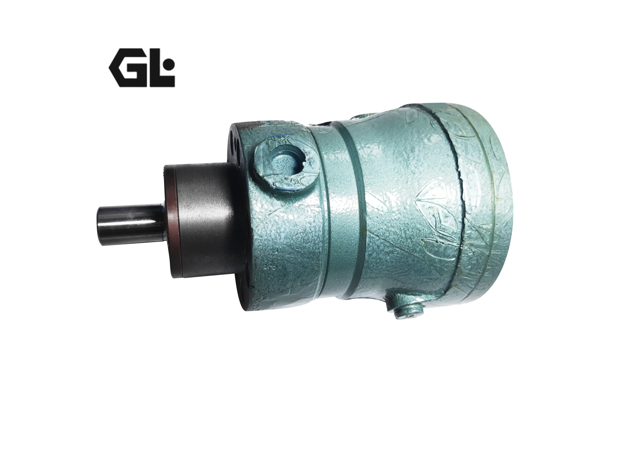

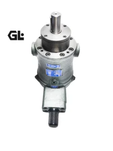
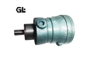
Product Overview
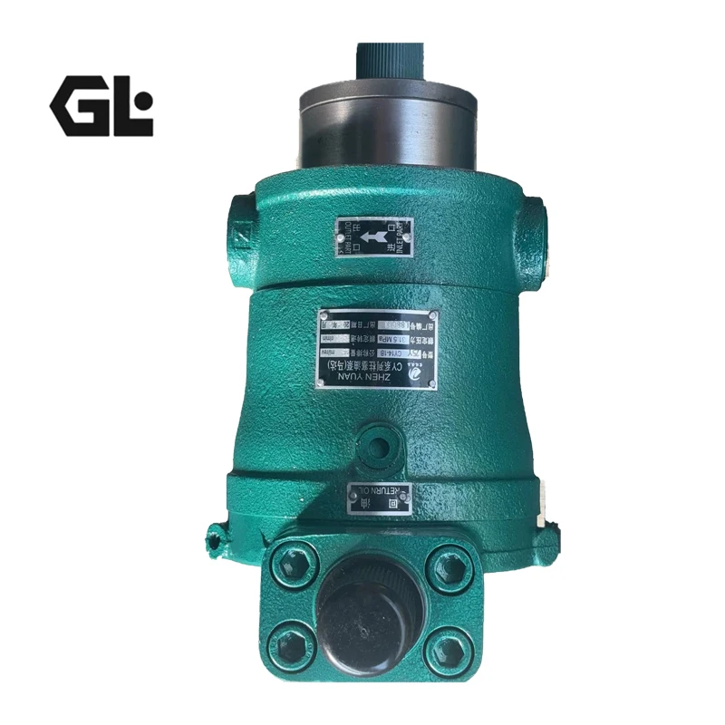
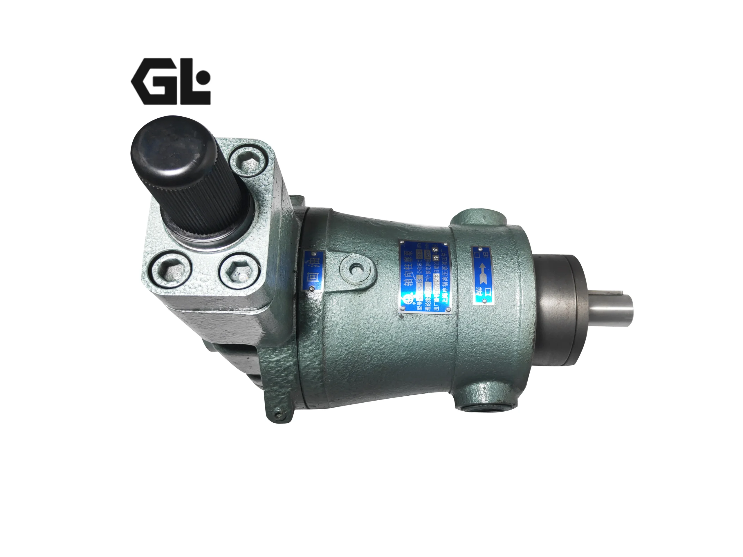
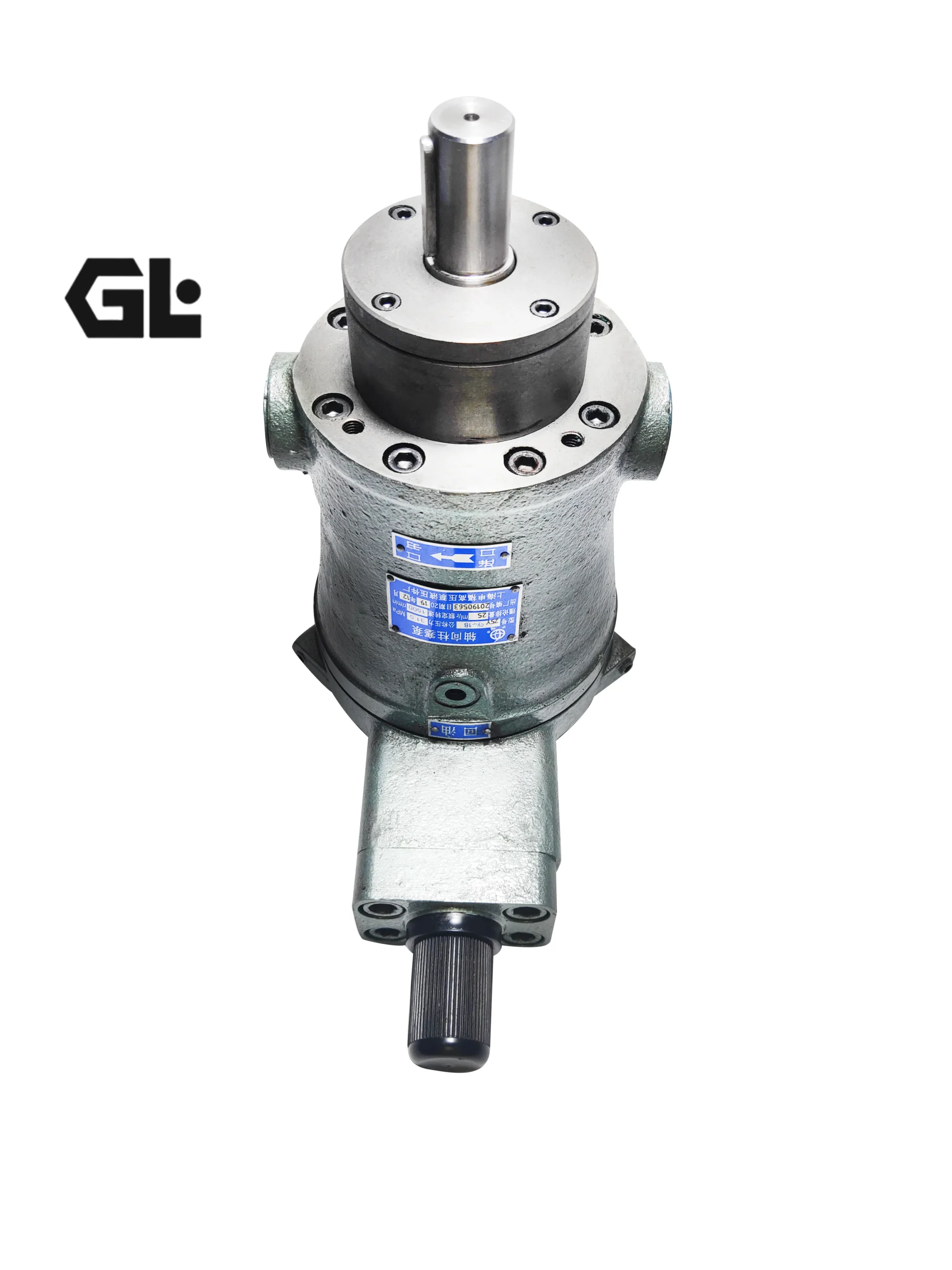
The 250YCY14-1B is a large-displacement swashplate-type pressure-compensated variable axial piston pump from the CY14-1B series, with a nominal displacement of 250 mL/r and a nominal pressure of 31.5 MPa (peak pressure up to 40 MPa). The pump features a valve-plate distribution, rotating cylinder barrel design in which displacement is steplessly adjusted through swashplate angle variation. Its defining characteristic is pressure-compensated variable control: as system pressure rises, output flow automatically decreases along an approximate constant-power curve; as pressure falls, flow automatically increases, achieving optimal matching of prime mover power.
The CY14-1B series covers displacements from 1.25 to 400 mL/r. The 250YCY14-1B is a large-flow specification within this series, delivering a theoretical flow of 375 L/min at 1500 rpm, maximum transmission power of 133.2 kW, and maximum theoretical torque of 1,272.4 N·m. The pump body employs a hydrostatic balance structure in which the slipper-to-swashplate and valve-plate-to-cylinder-barrel interfaces operate under pure liquid friction, eliminating the need for heavy-duty thrust bearings. This results in a simple structure, compact size, high efficiency, lightweight design, low noise, and strong self-priming capability.
Manufactured to exact CY14-1B series specifications, every unit features mounting dimensions, flange interfaces, and port layouts fully consistent with the original pump for true drop-in interchangeability — no piping or coupling modification required. Each pump undergoes 100% simulated operating condition testing before shipment, covering rated pressure loading, displacement mechanism response, and housing sealing integrity.
Technical Specifications
Model: 250YCY14-1B
Series: CY14-1B Series
Pump Type: Swashplate-type pressure-compensated variable axial piston pump (rotating cylinder barrel design)
Nominal Displacement: 250 mL/r
Nominal Pressure: 31.5 MPa (315 bar)
Peak Pressure: 40 MPa (400 bar)
Rated Speed: 1,500 rpm
Theoretical Flow at 1500 rpm: 375 L/min
Maximum Transmission Power: 133.2 kW
Maximum Theoretical Torque: 1,272.4 N·m
Control Type: Y-Type Pressure-Compensated Variable Control (Constant Power)
Number of Pistons: 7
Rotation Direction: Clockwise (viewed from shaft end); no marking indicates standard forward rotation
Mounting Flange: Φ280 mm (Dimension A)
Inlet Port Thread: M48×2
Recommended Hydraulic Fluid: N46 anti-wear hydraulic oil
Fluid Temperature Range: 30 °C – 55 °C (optimal); must not exceed 60 °C
Housing Material: Cast iron
Weight: Approx. 128 kg (160YCY reference data; confirm with nameplate)
Key Technical Advantages
Pressure-Compensated Variable Control for Constant Power: The 250YCY14-1B’s core technical feature is its pressure-compensated variable control. High-pressure oil enters the lower chamber of the control housing through internal passages. When spring force exceeds the hydraulic thrust on the servo piston, the variable piston pushes the swashplate to increase its angle and raise pump flow; when hydraulic thrust exceeds spring force, the servo piston blocks the oil passage, the variable piston moves up, and the swashplate angle decreases to reduce flow. This mechanism causes output flow to follow an approximate constant-power curve relative to output pressure — effectively preventing prime mover overload and improving energy efficiency in applications with severe load fluctuations such as forging presses and hydraulic presses.
Hydrostatic Balance Structure Design: The slipper-to-swashplate and valve-plate-to-cylinder-barrel interfaces employ hydrostatic balance oil film thickness design, enabling both critical running surfaces to operate under pure liquid friction without heavy-duty thrust bearing support. This design dramatically reduces mechanical wear during operation at 31.5 MPa, delivering industry-leading volumetric and overall efficiency while significantly extending pump service life.
High-Displacement High-Pressure Output Capability: The 250YCY14-1B delivers 375 L/min theoretical flow and 133.2 kW maximum transmission power at 250 mL/r displacement — the second-largest specification in the CY14-1B series after the 400YCY. The large-displacement swashplate design with seven-piston configuration provides ample high-pressure oil supply for large hydraulic presses and forging equipment.
Compact Structure with Superior Self-Priming Performance: The elimination of heavy-duty thrust bearings and adoption of hydrostatic balance structure results in a compact, lightweight pump. Strong self-priming capability allows above-reservoir mounting with suction height not exceeding 0.5 m. For pumps with flow rates exceeding 160 L/min, flooded suction installation is recommended for adequate oil supply.
CY14-1B Series Drop-In Interchangeability: The 250YCY14-1B’s mounting flange, shaft extension dimensions, and port layout fully comply with CY14-1B series standards, enabling true drop-in interchangeability with original pumps of the same specification. No coupling, piping, or mounting base modification is required — dramatically reducing equipment downtime.
Application Areas
Forging Equipment: Hydraulic presses, stamping presses, extrusion machines
Machine Tools: Planer-type milling machines, broaching machines, large CNC machine tools
Metallurgical Machinery: Rolling mill hydraulics, forging machinery, continuous casting equipment
Marine & Aviation: Marine hydraulic steering gear, deck machinery, aircraft hydraulic systems
Mining Machinery: Large hydraulic supports, mining hoisting equipment
Plastic & Rubber Machinery: Large injection molding machines, calenders
Water Conservancy: Large ship lock gate systems, hydropower station hydraulic controls
Construction Machinery: Cranes, excavators — auxiliary hydraulic systems
Expert Maintenance Tips
Shaft Alignment Requirements: Concentricity deviation between the pump shaft and drive shaft must be less than 0.1 mm to prevent excessive radial force, which causes noise, reduced efficiency, and increased failure frequency. Clean preservative grease from the pump housing before installation and tighten all connection bolts. The 250YCY14-1B features a Φ280 mm mounting flange — tighten flange bolts in diagonal sequence for even loading.
Initial Start-Up Filling and Bleeding: Before first use, the pump must be filled with clean N46 anti-wear hydraulic oil through the drain port — startup without pre-filling is strictly prohibited. Start at the lowest drive speed and observe a steady oil flow from the case drain port free of bubbles. An air bleed valve is recommended for eliminating vibration after air removal.
Rotation Direction Verification: The standard configuration is clockwise rotation (viewed from shaft end). For reverse rotation or hydraulic motor applications, special ordering is required. Incorrect drive direction will reverse the suction and pressure sides, causing severe rotating group damage within a short period.
Pressure Compensation Setting Adjustment: To adjust the pressure-compensated variable control: first turn the limit screw to the upper position, then adjust the spring sleeve according to the required flow and pressure variation range until the initial pressure at which flow begins to change meets requirements. Then set the limit screw to the final pressure at which flow no longer changes — the intermediate flow-pressure relationship is determined by the pump’s inherent design. Use calibrated pressure gauges and flow meters during adjustment.
Fluid Temperature and Cleanliness Management: Use N46 anti-wear hydraulic oil. Optimal oil temperature is 30 °C–55 °C; reservoir oil temperature must not exceed 60 °C. Heating or cooling is required when oil temperature falls below 15 °C or exceeds 60 °C. Pipelines must be strictly cleaned before installation — steel pipes require acid pickling and neutralization treatment; new oil must be filtered through an oil purifier when filling the reservoir. Regularly check fluid cleanliness and replace hydraulic oil and filter elements to extend pump service life and efficiency.
Case Drain Line Configuration: The case drain line must return directly to the reservoir with backpressure not exceeding 2 bar. The drain line inner diameter must be sufficient to ensure unobstructed drainage during cold-start high-viscosity conditions.