


Product Overview
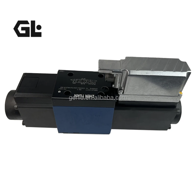
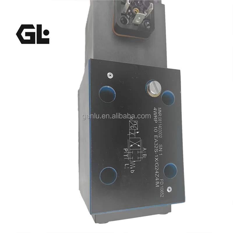
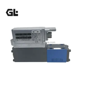
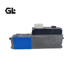
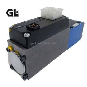
The 4WRPEH10C3B50L-2X/G24K0/F1M (Material No. 0811404819) and 4WRPEH10C1B100L-2X/G24K0/A1M (Material No. 0811404821) are direct-operated high-response proportional directional valves from Bosch Rexroth’s 4WRPEH10 series, featuring electrical position feedback (LVDT) and integrated on-board electronics (OBE). Both are built on the 2X component series, integrating the control amplifier directly onto the valve body and eliminating the external amplifier card required in conventional configurations.
Valves of type 4WRPEH are direct operated directional control valves with electrical position feedback and integrated electronics (OBE). The integrated electronics (OBE) compares the specified command value to the position actual value. In case of control deviations, the stroke solenoid will be activated. Due to the changed solenoid force, the control spool is adjusted against the spring. Stroke/control spool cross-section is controlled proportionally to the command value. In case of a command value presetting of 0, the electronics adjust the control spool to central position.
The 4WRPEH10C3B50L-2X mounts via subplate according to ISO 4401-05-04-0-05 at nominal size NG10 (Cetop 5), with maximum operating pressure of 315 bar at ports P/A/B and 250 bar at port T, and rated flow of 50 L/min at Δp = 70 bar per metering edge. Model code breakdown: “C3” denotes spool function (2:1 flow ratio), “B50L” specifies 50 L/min rated flow with linear flow characteristic (L), “G24K0” represents DC 24 V supply, and “F1M” indicates 4-20 mA current input signal.
The 4WRPEH10C1B100L-2X mounts according to the same standard, with maximum operating pressure of 315 bar at ports P/A/B and rated flow of 100 L/min at Δp = 70 bar per metering edge. Model code breakdown: “C1” denotes spool function (2:1 flow ratio), “B100L” specifies 100 L/min rated flow with linear flow characteristic (L), and “A1M” indicates ±10 V analog control signal.
Both valves support fail-safe functionality: in the deactivated condition, the spring is untensioned to a maximum and the valve is in fail-safe position. When supply voltage falls below the minimum, current command value drops below 2 mA (F1 interface, including command value line cable break), or the enable signal fails, the integrated electronics de-energize the control solenoids, and the spool is held in the safe position by compression springs.
As drop-in replacements, both valves are fully compatible with the OEM Rexroth specification in mounting interface, electrical connection, and performance characteristics. Every unit undergoes 100% simulation-based testing prior to shipment, covering null stability, flow linearity, step response, and internal leakage.
Technical Specifications
All parameters below are based on Bosch Rexroth official technical documentation (RE 29037) and verified supplier technical pages:
4WRPEH10C3B50L-2X/G24K0/F1M Technical Specifications:
Complete Model: 4WRPEH10C3B50L-2X/G24K0/F1M
Material Number (MNR): 0811404819
Brand: Bosch Rexroth
Product Series: 4WRPEH10 series, component series 2X
Product Type: Direct-operated high-response proportional directional valve with electrical position feedback and integrated electronics (OBE)
Spool Function: 4/4-way proportional directional valve
Spool Symbol: C3
Nominal Size: NG10 (ISO 4401-05-04-0-05 / Cetop 5)
Mounting: Subplate mounting
Max Operating Pressure (Ports P/A/B): 315 bar
Max Operating Pressure (Port T): 250 bar
Rated Flow: 50 L/min (at Δp = 70 bar per metering edge)
Flow Characteristic: L = linear flow characteristic
Drive Type: Direct-operated, stroke solenoid, no external pilot oil required
Position Feedback: LVDT displacement sensor, full closed-loop control
Integrated Electronics: OBE (on-board amplifier), analog signal
Supply Voltage: DC 24 V (model code ‘G24’)
Command Signal: 4 – 20 mA current input (model code ‘F1’, RS 200 Ω)
Electrical Connector: 6P+PE (DIN 43563-AM6)
Hydraulic Fluid: Mineral oil (HL, HLP per DIN 51524)
Seal Material: NBR nitrile rubber (model code ‘M’)
Protection Class: IP65
Weight: Approx. 7.1 kg
4WRPEH10C1B100L-2X/G24K0/A1M Technical Specifications:
Complete Model: 4WRPEH10C1B100L-2X/G24K0/A1M
Material Number (MNR): 0811404821
Brand: Bosch Rexroth
Product Series: 4WRPEH10 series, component series 2X
Product Type: Direct-operated high-response proportional directional valve with electrical position feedback and integrated electronics (OBE)
Spool Function: 4/4-way proportional directional valve
Spool Symbol: C1
Nominal Size: NG10 (ISO 4401-05-04-0-05 / Cetop 5)
Mounting: Subplate mounting
Max Operating Pressure (Ports P/A/B): 315 bar
Max Operating Pressure (Port T): 250 bar
Rated Flow: 100 L/min (at Δp = 70 bar per metering edge)
Flow Characteristic: L = linear flow characteristic
Drive Type: Direct-operated, stroke solenoid, no external pilot oil required
Position Feedback: LVDT displacement sensor, full closed-loop control
Integrated Electronics: OBE (on-board amplifier), analog signal
Supply Voltage: DC 24 V (model code ‘G24’)
Command Signal: ±10 V analog input (model code ‘A1’)
Electrical Connector: 6P+PE (DIN 43563-AM6)
Hydraulic Fluid: Mineral oil (HL, HLP per DIN 51524)
Seal Material: NBR nitrile rubber (model code ‘M’)
Protection Class: IP65
Weight: Approx. 7.1 kg
Note: Specifications are based on Bosch Rexroth official datasheet RE 29037 and verified supplier technical pages. Model code breakdown: 4WRP = 4/4 direct-operated proportional directional valve; E = integrated electronics (OBE); H = control spool/sleeve in servo quality; 10 = size NG10; C3/C1 = spool function (both C3 and C1 have 2:1 flow ratio); B50L/B100L = rated flow 50/100 L/min with L = linear flow characteristic; 2X = component series; G24K0 = DC 24 V supply, K0 connector configuration; F1 = 4-20 mA current input; A1 = ±10 V voltage input; M = NBR seals. The series optionally features an IO-Link interface for Industry 4.0 digital integration.
Key Technical Advantages
1. Direct-Operated Architecture with Integrated OBE for Plug-and-Play Operation
Both valves employ a direct-operated design in which the spool is driven directly by a stroke solenoid, eliminating the need for external pilot oil supply. The valve features a reliable and robust design, no pilot oil demand, suitability for position/velocity/pressure control, and high response sensitivity with minimal hysteresis. The integrated OBE electronics unit mounts the control amplifier directly on the valve body and is factory-calibrated, enabling operation with only a 24 V DC supply and command signal — no external amplifier card or associated wiring required. The integrated electronics compares the specified command value to the position actual value; in case of control deviations, the relevant solenoid is activated, and the changed magnetic force adjusts the control spool against the corresponding spring, with stroke proportional to the command value.
2. LVDT Full Closed-Loop Control with Servo-Quality Spool Assembly
Both valves’ core control architecture employs an LVDT displacement sensor to continuously measure actual spool position, feeding the signal back to the on-board OBE electronics for comparison against the command signal and dynamic correction of the solenoid drive current. The spool and sleeve are manufactured to servo quality (H = servo-quality control spool/sleeve), with clearance tolerances held to stringent specifications, delivering high response sensitivity and minimal hysteresis with repeatability at industrial servo-grade levels. In applications such as injection molding hold-pressure phases and precision press-fitting, this characteristic is decisive.
3. Linear Flow Characteristic with 2:1 Flow Ratio Spool Design
Both valves feature a linear (L) flow characteristic, maintaining a well-defined linear relationship between flow output and control current, facilitating closed-loop control system tuning and optimization. The C3 and C1 spool functions both provide a 2:1 flow ratio characteristic (P→A to B→T flow ratio of 2:1), suitable for applications requiring asymmetric flow control, such as differential hydraulic cylinder extend/retract speed matching.
4. Comprehensive Fail-Safe Protection with Digital Interface
Both valves feature comprehensive fail-safe protection: in the deactivated condition, the spring is untensioned to a maximum and the valve is in fail-safe position. When supply voltage falls below the minimum, current command value drops below 2 mA (F1 interface, including command value line cable break), the integrated electronics de-energize the control solenoids, and the spool is held in the safe position by compression springs. The series optionally supports an IO-Link digital interface for Industry 4.0 digital integration and condition monitoring. An optional electronics protection membrane (-967) prevents condensate formation in the integrated electronics housing, recommended for use outside industry-standard conditions with high ambient air humidity and significant cyclic temperature changes. An optional damping plate (D) reduces acceleration amplitudes on the on-board electronics at frequencies above 300 Hz.
5. 100% Simulation-Based Testing and Drop-In Interchangeability
Every 4WRPEH10 series valve undergoes 100% simulation-based testing prior to shipment. Test protocols cover rated flow calibration, hysteresis and linearity measurement, step-response verification, and internal leakage detection. As drop-in replacements, both valves are fully compatible with the OEM Rexroth specification in mounting dimensions (ISO 4401-05-04-0-05 interface), electrical interface (6P+PE connector per DIN 43563-AM6), and performance characteristics, enabling direct replacement of the original valve.
Application Areas
Injection Molding Machines: Closed-loop control of injection velocity and hold pressure for consistent part quality
Die Casting Equipment: High-speed dynamic pressure regulation and real-time switching control
Hydraulic Presses: Precision position/velocity control, force/position hybrid control
Material Testing Systems: Flow and pressure closed-loop control for electro-hydraulic servo loading systems, including high-frequency dynamic loading applications
Vibration Tables & Test Rigs: Precision flow control under high-frequency dynamic response conditions
Precision Press-Fitting Equipment: Servo-grade closed-loop force/position control
Machine Tool Hydraulic Systems: Flow and direction control for precision hydraulic feed axes
General Industrial Hydraulic Systems: Precision directional and flow control for automated production lines
Expert Maintenance Tips
Pre-Installation Checks:
Verify the manifold mounting surface conforms to ISO 4401-05-04-0-05 standard; surface roughness Rzmax ≤ 4 μm, flatness deviation ≤ 0.01 mm/100 mm
Flush all piping with clean hydraulic fluid prior to installation; ensure system cleanliness meets servo valve requirements
Inspect NBR O-rings for damage and confirm compatibility with the hydraulic fluid in use
Tighten mounting bolts in diagonal sequence to specified torque
Operational Maintenance:
Use a 5–10 μm precision pressure filter, specified without bypass and equipped with a contamination indicator
Recommended fluid: HL, HLP mineral oil per DIN 51524
Periodically inspect the integrated OBE electronics status indicators; confirm 24 V DC supply remains stable within allowable range
Monitor null output flow offset; significant increase indicates spool/sleeve wear or LVDT sensor anomaly
In high-humidity or significant temperature cycling environments, the electronics protection membrane (-967) is recommended to prevent condensate formation
In high-frequency excitation (>300 Hz) applications, the damping plate (D) is recommended to reduce acceleration amplitudes on the on-board electronics
Troubleshooting Guide:
Spool fails to actuate or responds abnormally: Check 24 V DC supply (electronics automatically de-energize below minimum supply voltage), verify command signal reaches the input correctly (4-20 mA or ±10 V), confirm 6P+PE connector engagement is reliable
Null-point drift: After ruling out fluid contamination, verify LVDT sensor feedback signal integrity; check whether the spool is stuck at a non-center position due to contamination
Insufficient flow: Confirm system supply pressure is within the 315 bar allowable range; check spool metering edges for partial blockage by contaminant particles
Electronics alarm: Verify command current is not below 2 mA (F1 interface, cable break detection trigger); check supply voltage is within normal range
Abnormal noise: Check that system return pressure does not exceed the 250 bar maximum; confirm no back-pressure blockage in the return line
Related Models:
R901265937 (4WRPH 6 C B24L-2X/G24Z4/M)
0811404131 (4WRPH 6 C B24L-2X/G24Z4/M-862)
0811404172 (4WRPH 6 C B25P-2X/G24Z4/M)
0811404130 (4WRPH 6 C B40L-2X/G24Z4/M-859)
0811404513 (4WRPH 6 C1 B40L-2X/G24Z4/M)
0811404162 (4WRPH 6 C1 B40P-2X/G24Z4/M)
0811404041 (4WRPH 6 C3 B02L-2X/G24Z4/M)
0811404033 (4WRPH 6 C3 B04L-2X/G24Z4/M)
0811404042 (4WRPH 6 C3 B04P-2X/G24Z4/M)
R901097266 (4WRPH 6 C3 B08L-2X/G24Z4/M-841)
0811404179 (4WRPH 6 C3 B12L-2X/G24K0/M-784)
0811404034 (4WRPH 6 C3 B12L-2X/G24Z4/M)
0811404161 (4WRPH 6 C3 B12L-2X/G24Z4/M-561)
0811404047 (4WRPH 6 C3 B15P-2X/G24Z4/M)
0811404520 (4WRPH 6 C3 B24L-2X/G24K0/M-784)
0811404035 (4WRPH 6 C3 B24L-2X/G24Z4/M)
0811404164 (4WRPH 6 C3 B24L-2X/G24Z4/M-561)
0811404043 (4WRPH 6 C3 B25P-2X/G24Z4/M)
0811404036 (4WRPH 6 C3 B40L-2X/G24Z4/M)
0811404174 (4WRPH 6 C3 B40L-2X/G24Z4/M-561)
0811404044 (4WRPH 6 C3 B40P-2X/G24Z4/M)
0811404515 (4WRPH 6 C4 B02L-2X/G24Z4/M)
0811404160 (4WRPH 6 C4 B04L-2X/G24Z4/M)
0811404037 (4WRPH 6 C4 B12L-2X/G24Z4/M)
0811404514 (4WRPH 6 C4 B12L-2X/G24Z4/V)
0811404048 (4WRPH 6 C4 B15P-2X/G24Z4/M)
0811404038 (4WRPH 6 C4 B24L-2X/G24Z4/M)
R901411228 (4WRPH 6 C4 B24L-2X/G24Z4/V)
0811404045 (4WRPH 6 C4 B25P-2X/G24Z4/M)
0811404039 (4WRPH 6 C4 B40L-2X/G24Z4/M)
0811404046 (4WRPH 6 C4 B40P-2X/G24Z4/M)
0811404032 (4WRPH 6 KB50L-2X/G24Z4/M)
0811404040 (4WRPH 6 KB50P-2X/G24Z4/M)
0811404177 (4WRPH 6 XB12L-2X/G24K0/M-843)
0811404166 (4WRPH 6 XB12L-2X/G24Z4/M-842)
0811404163 (4WRPH 6 XB24L-2X/G24Z4/M-842)
0811404175 (4WRPH 6 XB40L-2X/G24Z4/M-842)