

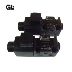
Product Overview
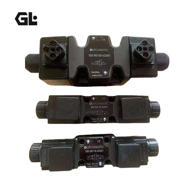
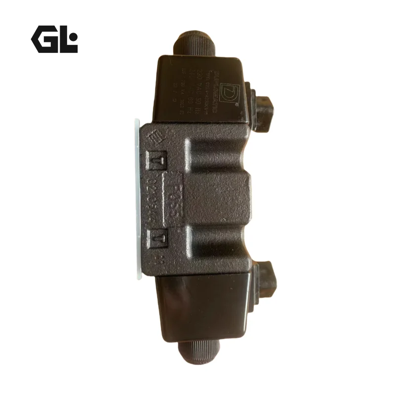
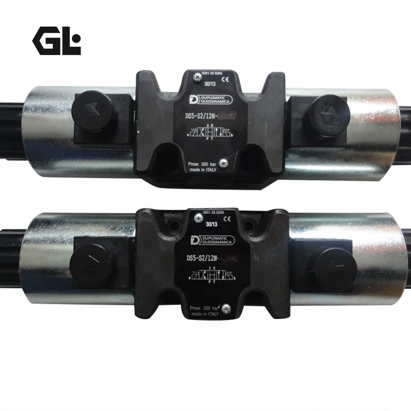
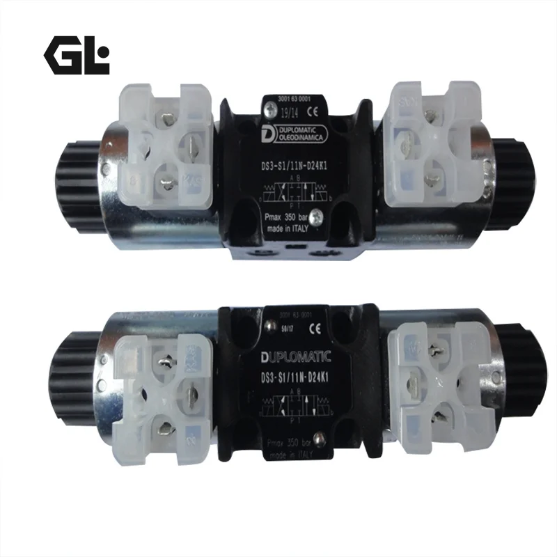
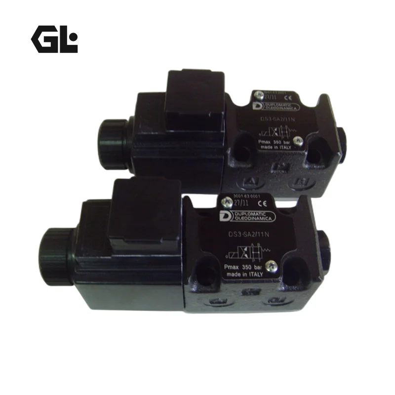
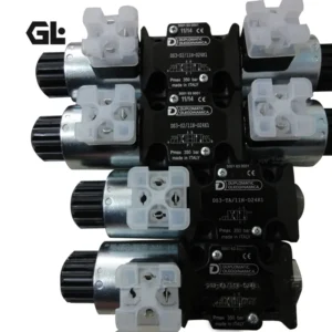
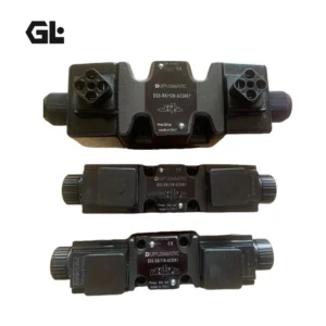
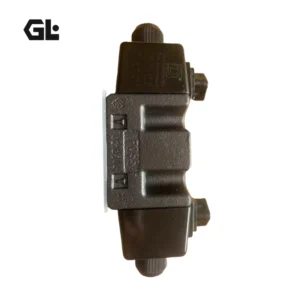
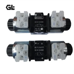
The Duplomatic DS3-RK/10N-A110K1 is a direct-operated solenoid directional control valve designed for industrial hydraulic flow-direction control.
This configuration uses the standard ISO 4401-03 / CETOP 03 subplate mounting interface and is rated for up to 350 bar at the P, A and B ports, with a maximum flow capacity of 100 L/min for the DS3 series. Duplomatic specifies a high-strength cast iron valve body, wide internal flow passages and wet-armature solenoids with interchangeable coils.
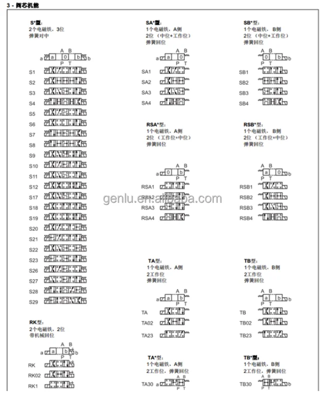
The most important configuration detail is the RK spool. According to the Duplomatic technical documentation, RK means:
- Two solenoids
- Two positions
- Mechanical retention
This means the valve is a switching directional valve rather than a proportional valve. The spool is mechanically retained after actuation instead of being automatically returned by a spring.
The complete configuration is:
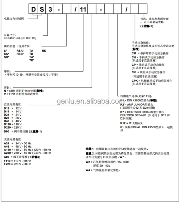
DS3-RK/10N-A110K1
- DS3: Direct-operated solenoid directional valve, ISO 4401-03
- RK: Two-position, two-solenoid spool with mechanical retention
- 10: Series number
- N: NBR seals for mineral-oil hydraulic fluids
- A110: 110 VAC / 50 Hz or 120 VAC / 60 Hz
- K1: EN 175301-803 electrical connection
For OEM replacement projects, the mounting interface, spool function, solenoid voltage, electrical connector, seal material and actual flow-pressure operating point should all be verified before claiming direct interchangeability.
Technical Specifications
- Model: DS3-RK/10N-A110K1
- Brand: Duplomatic
- Product Type: Direct-operated solenoid directional control valve
- Series: DS3
- Spool Type: RK
- Valve Function: Two-position directional switching
- Actuation: Two solenoids
- Retention: Mechanical retention
- Mounting: Subplate mounting
- Mounting Standard: ISO 4401-03
- Interface: CETOP 03
- Valve Body: High-strength iron casting
- Maximum Operating Pressure, P/A/B: 350 bar
- Maximum T-Port Pressure, AC Version: 160 bar
- Maximum Flow: 100 L/min
- Ambient Temperature: -20 to +50 °C
- Hydraulic Fluid Temperature: -20 to +80 °C
- Permitted Viscosity: 10 to 400 cSt
- Recommended Viscosity: 25 cSt
- Recommended Fluid Cleanliness: ISO 4406:1999 Class 20/18/15
- Seal Material: NBR
- Coil Type: A110
- Nominal Voltage: 110 VAC / 50 Hz; 120 VAC / 60 Hz
- Electrical Connection: K1, EN 175301-803
- A110 Coil Resistance at 20 °C: 33 Ω
- A110 Inrush Current: 1.76 A
- A110 Holding Current: 0.40 A
- A110 Inrush Power: 194 VA
- A110 Holding Power: 44 VA
- A110 Coil Code: 1902832
- Electrical Protection: IP65 for K1 connection when correctly installed with an equivalent-protection connector
- Maximum Switching Frequency: 18,000 operations/hour
- Duty Cycle: 100%
- Coil Insulation: Class H; AC valve impregnation Class F
- Approximate Weight: 2.0 kg for the double-solenoid DS3 configuration
- Displacement: Not applicable
- Maximum Speed: Not applicable
- Peak Pressure: No separate peak-pressure rating is specified; selection should be based on the applicable maximum operating pressure
- Switching-Time Data: Determined according to ISO 6403 and dependent on spool and solenoid configuration; RK performance should not be generalized from another spool variant.
Key Technical Advantages
1. Mechanical-retention RK configuration
The RK configuration uses two solenoids, two positions and mechanical retention.
Unlike a spring-centered directional valve, the spool is mechanically retained in the selected position. This makes the DS3-RK suitable for hydraulic circuits where the actuator flow path must remain in the selected state after the electrical switching event.
2. 350 bar high-pressure capability
The DS3 family supports up to 350 bar at the P, A and B ports, providing a robust solution for high-pressure industrial hydraulic circuits.
However, 350 bar should be treated as the maximum specified operating pressure rather than a universal recommendation for every flow condition. Actual pressure-flow combinations must be checked against the applicable operating-limit curves.
3. Up to 100 L/min flow capacity
The DS3 is specified for up to 100 L/min.
Its wide internal flow passages are designed to reduce pressure drops through the valve. This is particularly useful in high-cycle hydraulic systems where unnecessary throttling losses can increase heat generation and energy consumption.
4. High-strength cast iron construction
The valve body is produced from high-strength iron castings.
This construction provides the structural rigidity required for high-pressure hydraulic service while allowing complex internal flow passages to be integrated into a compact CETOP valve body.
5. Wet-armature solenoid design
The DS3 uses wet-armature solenoids in which the moving armature operates in an oil-filled environment.
Duplomatic also specifies interchangeable coils, while the coil can be rotated through 360° to accommodate available installation space. This modular architecture is advantageous for maintenance and machine-service applications.
6. Standard CETOP 03 interface
The ISO 4401-03 / CETOP 03 interface facilitates integration into standard hydraulic manifolds, subplates and OEM valve assemblies.
This standard interface supports replacement engineering, but true interchangeability still requires matching the spool function, electrical configuration and hydraulic operating conditions.
7. 110 VAC industrial solenoid configuration
The A110 designation corresponds to 110 VAC at 50 Hz or 120 VAC at 60 Hz.
The published inrush and holding electrical characteristics allow engineers to correctly size control relays, protection devices and electrical wiring.
8. Strong candidate for OEM replacement
For DS3-RK/10N-A110K1 replacement projects, the key interchangeability criteria include:
- ISO 4401-03 mounting interface
- RK spool logic
- Two-solenoid operation
- Mechanical retention
- A110 coil voltage
- K1 connector
- NBR sealing
- 350 bar P/A/B pressure rating
- Actual hydraulic flow and pressure-drop requirements
Our replacement engineering approach can reproduce the required mounting and operating characteristics and validate each unit through 100% simulated operating-condition testing, including switching behavior, pressure, flow, thermal performance and continuous operation.
Application Areas
Typical applications include:
- Hydraulic presses
- Injection molding machinery
- Die-casting equipment
- Metal forming machinery
- Automated hydraulic clamping systems
- Hydraulic tooling
- Industrial hydraulic power units
- Hydraulic lifting equipment
- Machine-tool hydraulic systems
- Steel and metallurgical auxiliary hydraulic circuits
- OEM hydraulic manifold assemblies
- Hydraulic circuits requiring mechanically retained actuator positions
The RK configuration is particularly suitable where the hydraulic flow path must remain in the selected position without spring return.
Expert Maintenance Tips
1. Pay attention to mounting orientation
The Duplomatic documentation recommends a horizontal axis orientation for RK mechanical-retention versions without springs. Replacement installations should preferably preserve the original valve orientation.
2. Do not confuse A110 with 110 VDC
A110 is an AC solenoid configuration:
- 110 VAC / 50 Hz
- 120 VAC / 60 Hz
It is not the 110 VDC configuration.
Always verify the coil marking and machine control voltage before energizing the valve.
3. Keep the CETOP mounting surface clean
CETOP subplate valves depend on a clean and correctly prepared mounting surface.
During installation:
- Clean the valve mounting face
- Inspect all O-rings
- Prevent metal particles from entering the ports
- Use the correct mounting screws
- Tighten according to the specified fastening requirements
4. Control hydraulic contamination
Duplomatic specifies ISO 4406:1999 Class 20/18/15 fluid cleanliness for the DS3 family.
Contamination can increase spool friction and interfere with reliable spool movement. In an RK valve, this may result in a solenoid being energized while the spool does not complete the expected shift.
5. Monitor T-port back pressure
For the AC configuration, the documentation specifies 350 bar at P/A/B but 160 bar at T.
Therefore, the valve should never be evaluated only from the “350 bar” figure. T-line back pressure must also be checked, especially in multi-valve return manifolds with dynamic back pressure.
6. Check both inrush and holding conditions
For the A110 coil, the published values are:
- Inrush current: 1.76 A
- Holding current: 0.40 A
- Inrush power: 194 VA
- Holding power: 44 VA
Abnormal coil heating, repeated switching or excessive current should trigger inspection of the supply voltage, connector, solenoid tube and spool movement rather than simply replacing the coil.