
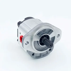
Product Overview
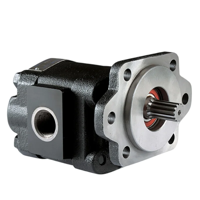
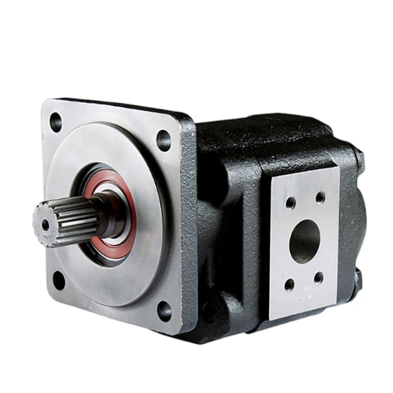
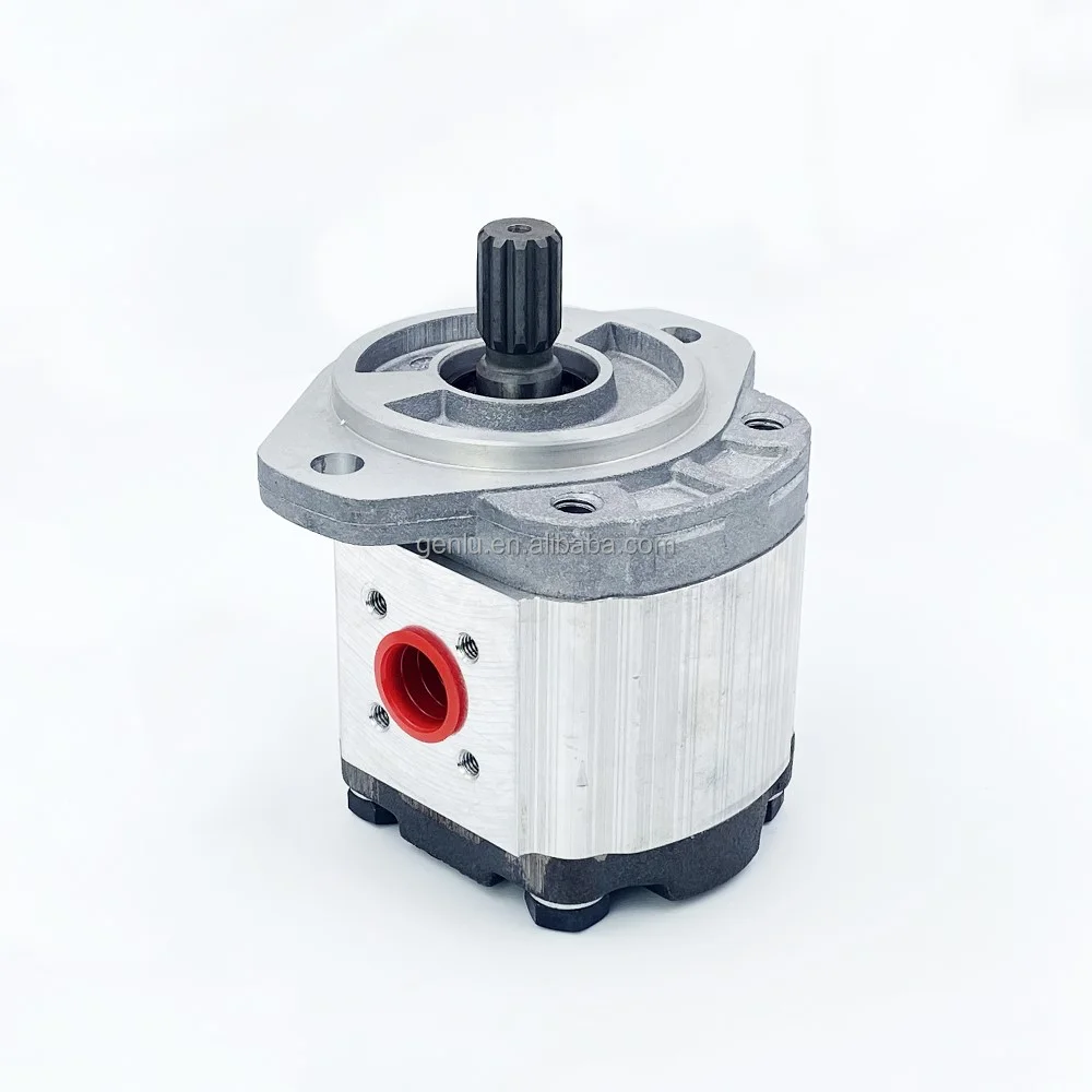
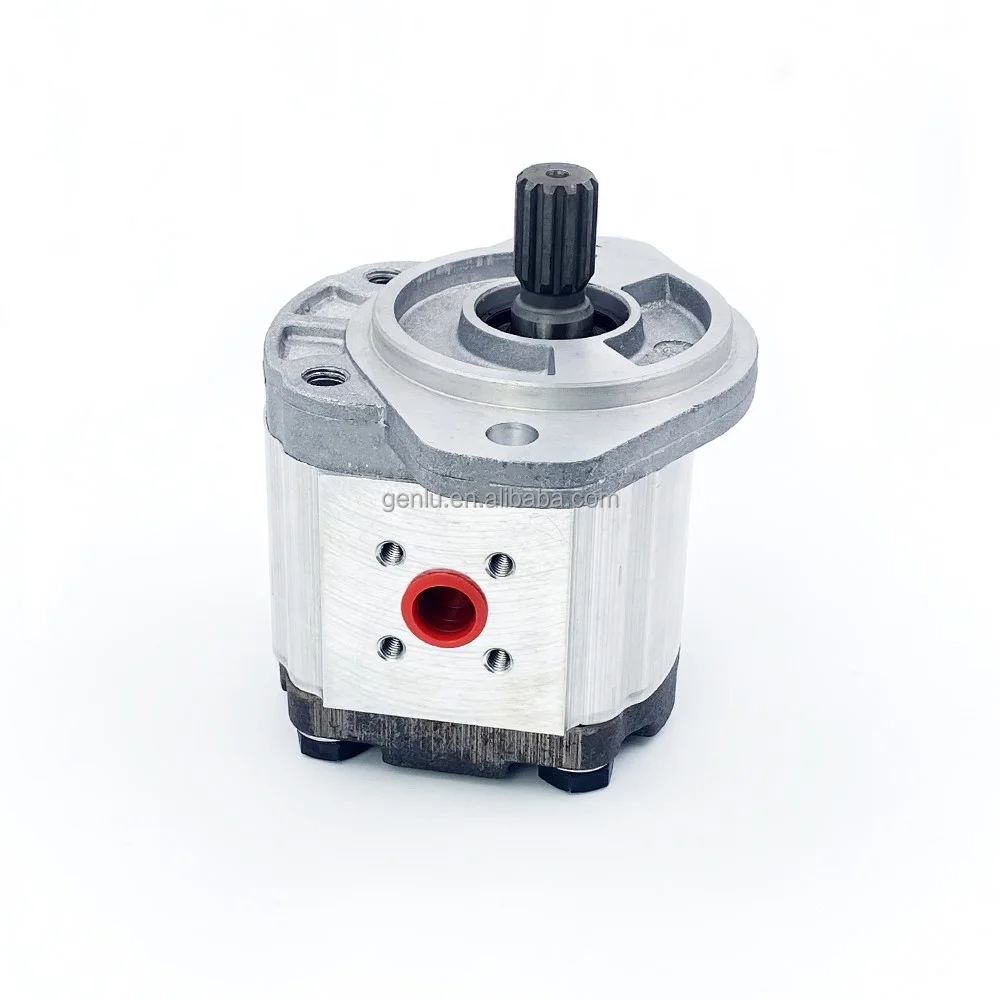
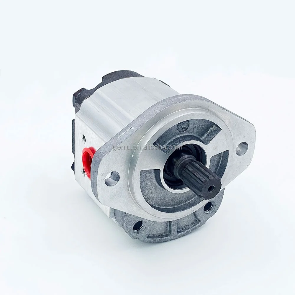
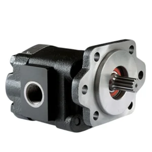
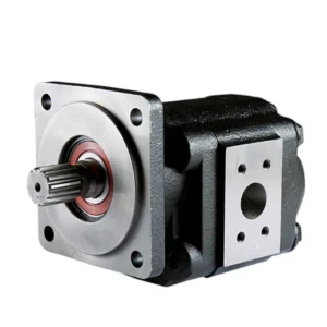
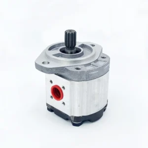
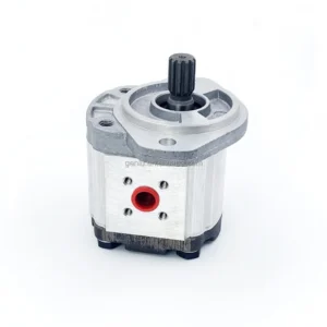
The PGP511M0140CS4D3NE5E3B1B1 is an aluminum external gear pump from the Parker Hannifin PGP511 series. This model belongs to the PGP500 Series Group 1 compact platform, with a displacement of 14 cm³/rev. It corresponds to Parker part number 334 9111 531.
The PGP500 Series gear pumps are advanced performance versions of the international “bushing block” style pumps, offering superior performance, high efficiency, and low noise operation at high operating pressures. The PGP511 features optimized gear design and flow distribution geometry, minimizing pressure pulsation for exceptionally smooth and quiet operation. The series is available in four frame sizes (PGP 503, 505, 511, 517) with displacements ranging from 0.8 to 33 cm³/rev.
Every unit is manufactured to original equipment specifications, ensuring 100% drop-in interchangeability with genuine Parker PGP511 series pumps without any system modifications. Each pump undergoes rigorous 100% simulated duty-cycle testing on dedicated test benches to validate pressure-flow-efficiency performance curves.
Brand Disclaimer: This product is a high-quality compatible replacement engineered for full interchangeability with Parker Hannifin original equipment. All Parker brand names and model codes are referenced solely to indicate compatibility and interchangeability. This product is manufactured by an independent producer and is not an original Parker product.
Technical Specifications
Model Code: PGP511M0140CS4D3NE5E3B1B1
Parker Part Number: 334 9111 531
Brand Series: Parker Hannifin PGP511 (PGP500 Series)
Pump Type: Fixed Displacement Gear Pump
Displacement: 14 cm³/rev
Series Displacement Range: 6 – 33 cm³/rev
Continuous Operating Pressure: 250 bar
Maximum Operating Pressure: 250 bar (3625 psi)
Maximum Speed: 3,500 rpm
Minimum Speed: 500 rpm
Rotation Direction: Clockwise (CW)
Housing Material: Aluminum
Construction: Three-piece modular construction
Bearings: Journal Bushings
Thrust Plates: Pressure Balanced Thrust Blocks
Seals: NBR (Nitrile rubber)
Hydraulic Fluid: Standard Hydraulic Fluids, Fire Resistant, Water-Glycol, Biodegradable
Recommended Viscosity Range: 50 – 7500 SUS
Operating Temperature Range: -15°C to +80°C
Maximum Flow Rate (Series) : 66 L/min
Mounting Options: SAE, ISO, DIN
Port Connections: SAE, ISO, NPT, BSPP, ODT
Port Location: Side Ports, Rear Ports
Thru-Drive Capability: No
Weight: Approx. 4.5 kg
Country of Origin: Czech Republic
Key Technical Advantages
1. Lightweight Aluminum Alloy Construction
The high-strength aluminum alloy housing delivers a total weight of only approximately 4.5 kg—significantly lighter than cast iron equivalents. This substantial weight reduction makes it ideal for weight-sensitive mobile equipment and vehicle-mounted systems.
2. Pressure-Balanced Thrust Blocks & Journal Bushings – High Efficiency & Long Life
Integrated pressure-balanced thrust blocks automatically compensate for gear end clearance under high pressure, significantly reducing internal leakage. Paired with journal bushings, friction losses are minimized while extending service life.
3. Three-Piece Modular Construction – Maximum Flexibility
The three-piece modular construction provides excellent distribution flexibility for system design. Supports single, tandem, and multiple pump configurations to meet diverse hydraulic system requirements.
4. Broad Speed & Temperature Operating Range
Supports a wide speed range of 500 to 3,500 rpm with operating temperature range from -15°C to +80°C. Maintains stable flow characteristics from cold start to high-speed continuous duty.
5. Extensive Integrated Valve Options
The PGP511 series supports integration of multiple control valve functions including: Relief, Load Sense, Priority, and Unloading valves. Flexible configuration reduces external valve groups and piping, improving system integration.
6. 100% Simulated Duty-Cycle Testing
Every pump is 100% tested on dedicated hydraulic test benches under simulated real-world operating conditions—validating pressure-flow characteristics and efficiency curves at rated pressure (250 bar) and full speed range—ensuring zero-defect, plug-and-play performance upon installation.
Application Areas
Aerial Lifts: Boom elevation and rotation hydraulic systems
Agricultural Machinery: Tractor hydraulic systems, combine harvester implement drives
Construction Equipment: Mini-excavators, loader auxiliary hydraulic systems
Forestry Equipment: Wood processing and material handling equipment
Material Handling Equipment: Forklifts, telehandler hydraulic systems
Power Steering Systems: Priority valve configurations available
Brake Systems: Brake pump applications
Hydraulic Power Units (HPU) : Industrial and mobile power stations
Vocational & Municipal Equipment: Street sweepers, mowers, etc.
Expert Maintenance Tips
1. Fluid Cleanliness Control
Maintain system fluid cleanliness to ISO 4406 19/17/13 or better. Install a ≤10 μm absolute filtration filter upstream of the inlet port to prevent particle contamination from damaging precision gear pairs, journal bushings, and thrust plates.
2. Inlet Line Requirements
Keep suction lines short and straight with adequate diameter—not less than the port size. Inlet pressure must be maintained between 0.8 – 2.0 bar (absolute) . Recommended suction line flow velocity: ≤1.5 m/s to prevent cavitation from excessive inlet resistance.
3. Coupling Alignment Precision
Flexible couplings are recommended for direct drive. Ensure pump shaft-to-drive shaft coaxiality deviation ≤0.05 mm and angular deviation ≤0.5° during installation. If the drive involves sprockets or V-belt pulleys, an independent outboard bearing MUST be installed to protect pump shaft bearings.
4. First-Start Priming Procedure
Before initial startup, prime the pump by bleeding air through the drain port or a loosened outlet fitting. Perform 2–3 jog starts with the outlet open (no load) until oil fills the pump cavity without air bubbles, then connect the load circuit for full operation.
5. Fluid Temperature Monitoring
Recommended operating temperature range: -15°C to +80°C. During cold starts when viscosity exceeds the recommended range (>7500 SUS), ensure adequate suction conditions or preheat the fluid.
6. Rotation Direction Confirmation
This model is standard configured for clockwise (CW) rotation. Always verify that the drive motor/engine rotation matches the pump before installation. Specify counterclockwise (CCW) configuration when ordering if required.