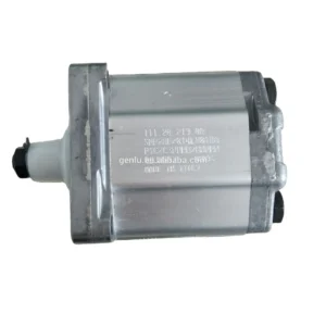
Product Overview
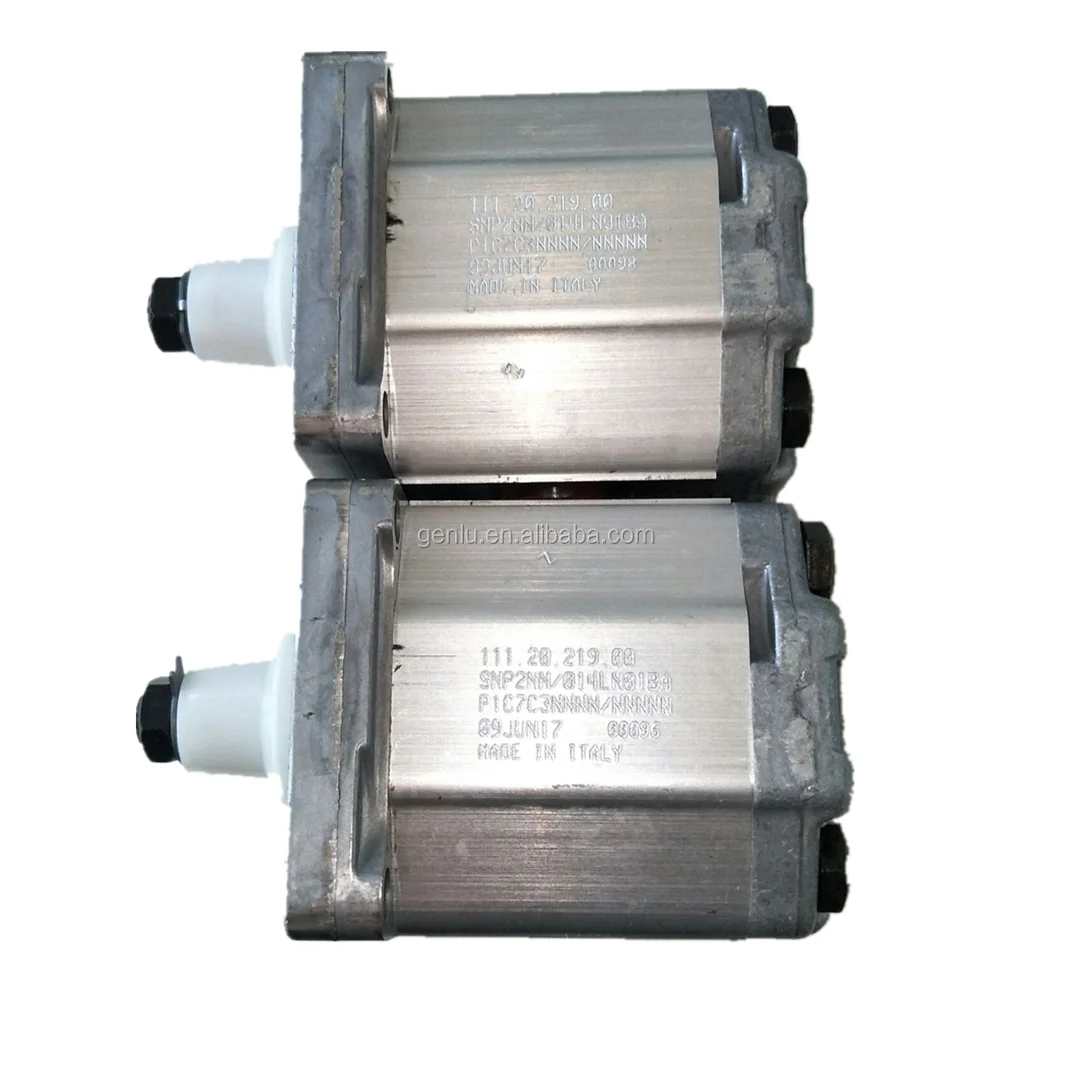
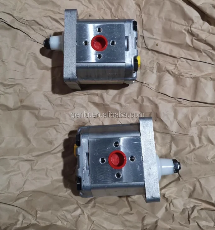
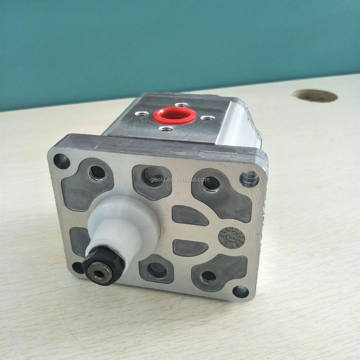
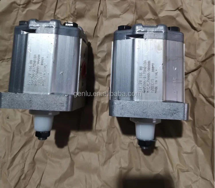
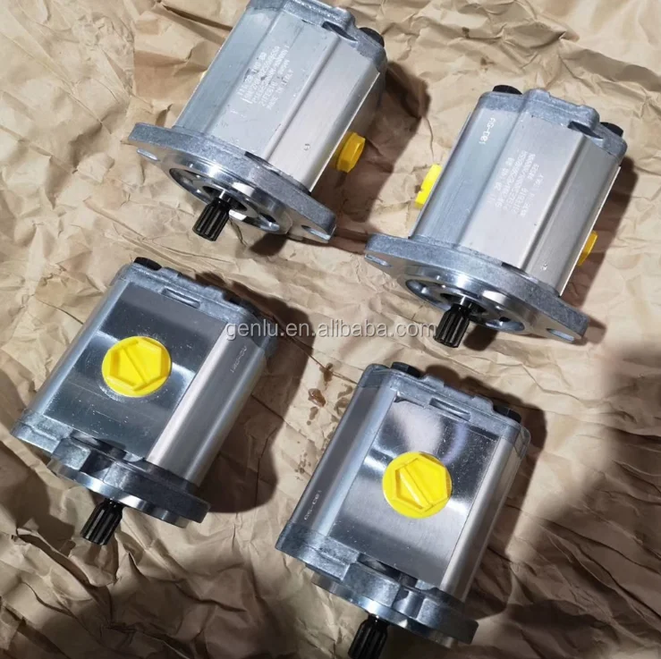
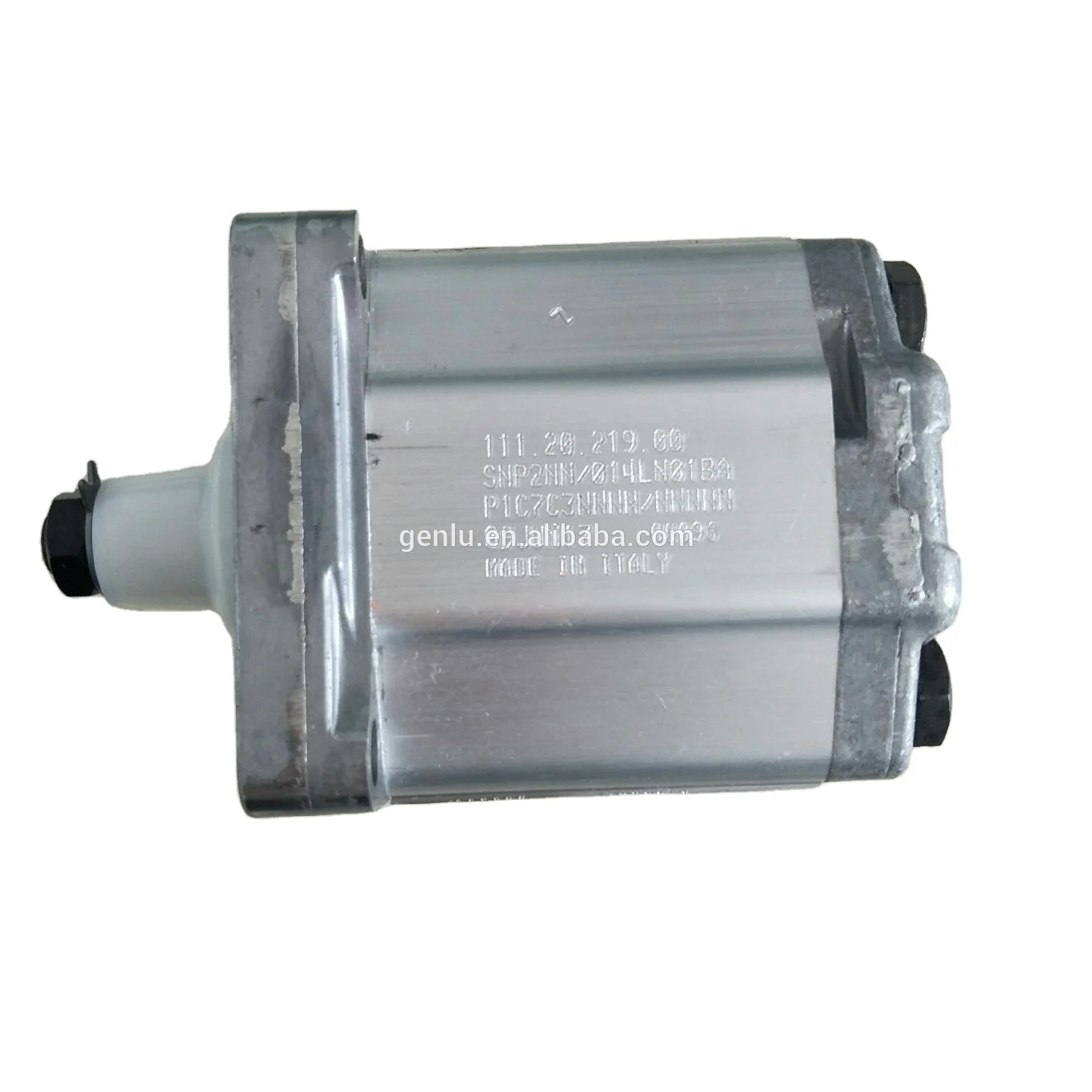
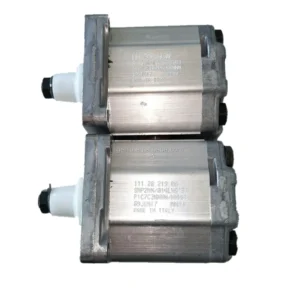
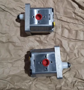
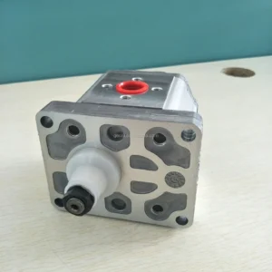
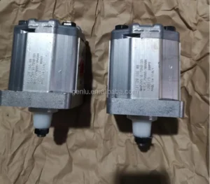
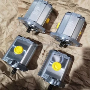
The SNP2NN/025RN06SAP1E6E5NNNN/NNNNN is a Group 2 aluminum external gear pump from the Danfoss GearMe product line. This model features a displacement of 25.2 cm³/rev and corresponds to Danfoss part number 111.20.140.00.
The SNP2NN series belongs to the Danfoss GearMe Group 2 medium-frame high-performance fixed-displacement aluminum external gear pump family. Engineered with a high-strength aluminum alloy housing and precision-ground gear pairs, the pump delivers compact structure, light weight, high efficiency, and low noise. Formerly the Turolla product line, this series is renowned for its efficiency, reliability, and compact design, and is widely used in construction equipment, agricultural machinery, and industrial hydraulic systems.
Every unit is manufactured to original equipment specifications, ensuring 100% drop-in interchangeability with genuine Danfoss SNP2NN series pumps without any system modifications. Each pump undergoes rigorous 100% simulated duty-cycle testing to validate pressure-flow-efficiency performance curves.
Brand Disclaimer: This product is a high-quality compatible replacement engineered for full interchangeability with Danfoss original equipment. All Danfoss brand names and model codes are referenced solely to indicate compatibility and interchangeability. This product is manufactured by an independent producer and is not an original Danfoss product.
Technical Specifications
Model Code: SNP2NN/025RN06SAP1E6E5NNNN/NNNNN
Danfoss Part Number: 111.20.140.00
Brand Series: Danfoss GearMe SNP2NN (Group 2)
Product Type: Fixed Displacement External Gear Pump
Displacement: 25.2 cm³/rev
Continuous Operating Pressure: 160 bar
Peak Pressure: 175 bar
Maximum Speed: 3,000 rpm
Maximum Flow Rate: 75.6 L/min
Volumetric Efficiency: ≥ 94%
Overall Efficiency: 85% – 92%
Rotation Direction: Right-hand (Clockwise / R)
Mounting Flange: SAE A 2-bolt flange, pilot diameter 82.55 mm (code 06)
Drive Shaft Type: SAE J498 splined shaft, 9T 16/32DP (code SA)
Inlet Port: 1-1/16″ UNF threaded (code E6)
Outlet Port: 7/8″ UNF threaded (code E5)
Rear Cover: Standard cover (P1)
Valve Configuration: No valve (NNN)
Seals: Standard NBR (Nitrile rubber)
Housing Material: High-strength aluminum alloy
Operating Temperature Range: -20°C to +80°C
Recommended Fluid Viscosity: 10 – 800 cSt
Net Weight: 3.3 kg
Gross Weight Reference: Approx. 13 kg (including packaging)
Key Technical Advantages
1. Lightweight Aluminum Alloy Construction
The high-strength aluminum alloy housing delivers a total net weight of only 3.3 kg—significantly lighter than cast iron equivalents. This substantial weight reduction makes it ideal for weight-sensitive construction equipment, agricultural machinery, and other mobile hydraulic applications.
2. High Efficiency & Low-Noise Operation
The SNP2NN series is renowned for its efficiency, reliability, and compact design. Volumetric efficiency reaches 94% or higher, with overall efficiency of 85% – 92%. Precision gear manufacturing and optimized tooth profiles ensure low-noise operation, making it suitable for noise-sensitive working environments.
3. Broad Speed & Temperature Operating Range
Supports speeds up to 3,000 rpm with operating temperatures from -20°C to +80°C. Recommended viscosity range of 10 – 800 cSt ensures stable flow characteristics from cold start to high-speed continuous duty.
4. SAE International Standard Interface – 100% Drop-In Interchangeability
Featuring SAE A 2-bolt flange (pilot diameter 82.55 mm) and SAE J498 9T splined shaft. Fully compliant with international interchange standards—delivers 100% drop-in interchangeability with genuine Danfoss SNP2NN series pumps.
5. High Cleanliness Standards for Extended Service Life
Strict manufacturing and cleanliness standards ensure precision gear pairs maintain optimal performance throughout the pump’s service life. Standard NBR seals are compatible with most mineral-based hydraulic fluid systems.
6. 100% Simulated Duty-Cycle Testing
Every pump is 100% tested on dedicated hydraulic test benches under simulated real-world operating conditions—validating pressure-flow characteristics and efficiency curves at rated pressure (160 bar), peak pressure (175 bar), and full speed range—ensuring zero-defect, plug-and-play performance upon installation.
Application Areas
Construction Equipment: Mini-excavators, loader auxiliary hydraulic systems
Agricultural Machinery: Tractor hydraulic systems, combine harvester implement drives
Material Handling Equipment: Forklifts, lift platform hydraulic systems
Industrial Hydraulic Systems: Machine tools, press hydraulic systems
Mobile Equipment: Aerial work platforms, vehicle-mounted auxiliary hydraulics
Expert Maintenance Tips
1. Fluid Cleanliness Control
Maintain system fluid cleanliness to ISO 4406 19/17/14 or better. Install a 10–25 μm absolute filtration filter upstream of the inlet port to prevent particle contamination from damaging precision gear pairs.
2. Inlet Line Requirements
Keep suction lines short and straight with adequate diameter—not less than the 1-1/16″ UNF port size. Recommended suction line flow velocity: ≤1.5 m/s to prevent cavitation from excessive inlet resistance. Inlet pressure must be maintained between 0.8–2.0 bar (absolute) .
3. Coupling Alignment Precision
Ensure pump shaft-to-drive shaft coaxiality deviation ≤0.05 mm and angular deviation ≤0.5° during installation. Flexible couplings are strongly recommended. If the drive involves sprockets or V-belt pulleys, an independent outboard bearing MUST be installed to protect the pump shaft.
4. First-Start Priming Procedure
Before initial startup, prime the pump by bleeding air through the drain port or a loosened outlet fitting. Perform 2–3 jog starts with the outlet open (no load) until oil fills the pump cavity without air bubbles, then connect the load circuit for full operation.
5. Viscosity & Temperature Monitoring
Recommended operating viscosity: 10 – 800 cSt. During cold starts when viscosity exceeds the recommended range, ensure adequate suction conditions or preheat the fluid. Operating temperature range: -20°C to +80°C.
6. Rotation Direction Confirmation
The “R” code in this model indicates right-hand (clockwise) rotation. Always verify that the drive motor/engine rotation matches the pump before installation. Specify left-hand (counterclockwise) configuration by selecting the “L” variant if required.