



Product Overview
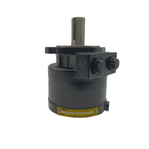
The 111A-106-AT-0-F and 112A-088-AT-0-F are flagship models in the Parker Nichols™ 110A Series of Low Speed High Torque (LSHT) orbital hydraulic motors, available in variants including 111A-106-AS-0 and 112A-088-AM-0-F. Featuring a one-piece solid fixed axis shaft design that eliminates the torque link used in conventional orbit motors, this series dramatically reduces internal spline stresses while increasing motor life and the ability to withstand rapid reversals. The 111A-106-AT-0-F offers a geometric displacement of 174 cm³/rev, while the 112A-088-AT-0-F delivers 144 cm³/rev. Both models achieve complete drop-in interchangeability with Parker originals in SAE A 2-bolt mounting flange, 1″ 6B spline shaft, and port configuration.
The 110A Series is built around a pressure-loaded power element and wear-compensated design: the power element is continuously pressure-loaded against internal leakage for high volumetric efficiency, and the wear compensation ensures that volumetric efficiency never degrades throughout the motor’s service life. This series delivers up to 7200 lb-in (approximately 813 N·m) of torque in just 6.6 inches (approximately 168 mm) of length, making it one of the most compact hydraulic motors in its class.
Every motor undergoes 100% simulated load testing before shipment, with protocols covering output torque verification at rated pressure, volumetric efficiency measurement at multiple speed points, internal leakage testing, and overspeed validation.
Technical Specifications
Basic Specifications
Model: 111A-106-AT-0-F / 112A-088-AT-0-F
Variant Models: 111A-106-AS-0 / 112A-088-AM-0-F
Motor Type: Low Speed High Torque (LSHT) Orbital Motor
Product Series: Parker Nichols™ 110A Series
Mounting Flange: SAE A 2-Bolt
Shaft Type: 1″ 6B Spline (Code 1), optional 1″ Keyed (Code 0), 25 mm Keyed (Code 2)
Port Size: 7/8″-14 SAE O-Ring
Max. Dynamic Side Load at Key: 1450 lb (658 kg)
Weight: Approx. 8.4 kg (111A-106) / 8.0 kg (112A-088)
111A-106-AT-0-F Performance Data (Displacement Code 106 / 174 cm³/rev)
Geometric Displacement: 174 cm³/rev [10.6 in³/rev]
Max. Pressure Differential (Continuous): 155 bar [2250 psi]
Max. Pressure Differential (Intermittent): 210 bar [3000 psi]
Max. Operating Speed: 654 rpm
Max. Torque (Continuous): 380 N·m [3360 lb-in]
Max. Torque (Intermittent): 470 N·m [4164 lb-in]
Max. Intermittent Flow: 114 L/min [30 gal/min]
Weight: Approx. 8.4 kg [18.4 lb]
112A-088-AT-0-F Performance Data (Displacement Code 088 / 144 cm³/rev)
Geometric Displacement: 144 cm³/rev [8.8 in³/rev]
Max. Pressure Differential (Continuous): 172 bar [2500 psi]
Max. Pressure Differential (Intermittent): 210 bar [3000 psi]
Max. Operating Speed: 787 rpm
Max. Torque (Continuous): 348 N·m [3080 lb-in]
Max. Torque (Intermittent): 589 N·m [5215 lb-in]
Max. Intermittent Flow: 114 L/min [30 gal/min]
Weight: Approx. 8.0 kg [17.5 lb]
Full 110A Series Displacement Range
110A 036: 59 cm³/rev, 898 rpm max, 126 N·m continuous torque
110A 054: 89 cm³/rev, 942 rpm max, 199 N·m continuous torque
110A 071: 116 cm³/rev, 716 rpm max, 278 N·m continuous torque
110A 088: 144 cm³/rev, 787 rpm max, 348 N·m continuous torque
110A 106: 174 cm³/rev, 654 rpm max, 380 N·m continuous torque
110A 129: 211 cm³/rev, 537 rpm max, 458 N·m continuous torque
110A 164: 269 cm³/rev, 423 rpm max, 517 N·m continuous torque
110A 189: 310 cm³/rev, 420 rpm max, 627 N·m continuous torque
110A 241: 395 cm³/rev, 288 rpm max, 622 N·m continuous torque
Materials & Construction
Housing: High-strength cast iron
Gear Set: Carburized and hardened alloy steel, pressure-loaded power element
Output Shaft: One-piece solid fixed axis shaft, no torque link
Bearings: Tapered roller bearings, 1450 lb dynamic side load capacity
Seals: NBR standard (F code)
Key Technical Advantages
1. One-Piece Solid Shaft with Low Internal Stress Design
The 110A Series features a one-piece solid fixed axis shaft design that eliminates the torque link used in conventional orbit motors. This design allows full stationary spline contact between shaft and rotor, fundamentally eliminating the internal spline stress concentration caused by torque links, significantly extending motor life and enhancing the ability to withstand rapid reversals. The straight shaft can also be extended through the rear cover for mounting parking brakes, encoders, or auxiliary drive functions, enabling speed readout or closed loop control for maximum system integration flexibility.
2. Pressure-Loaded Power Element with Wear Compensation
The 110A Series incorporates a pressure-loaded power element that is continuously pressure-loaded against internal leakage during operation, achieving high volumetric efficiency. More importantly, the series features a wear-compensated design—as motor operating hours accumulate, the compensation mechanism automatically adjusts the power element position to maintain sealing clearance, keeping volumetric efficiency constant throughout the entire service life. This characteristic is critical for industrial applications requiring long-term consistent output.
3. Superior Power Density and Compact Construction
The 110A Series leads its class in power density. The 111A-106 and 112A-088 models deliver up to 589 N·m (5215 lb-in) of intermittent output torque in a length of only approximately 168 mm, making them among the most compact hydraulic motors in their class. Low internal pressure drop design translates to high mechanical efficiency and greater flow capability, enabling higher power output within constrained installation spaces.
4. High Side Load Capacity and Rugged Construction
The output shaft end accommodates dynamic side loads up to 1450 lb (658 kg), suitable for applications involving direct drive of gears, sprockets, or pulleys. The combination of a rugged cast iron housing and high-precision tapered roller bearings ensures that the motor does not experience excessive shaft deflection under side loads, preserving gear mesh precision and long-term shaft seal reliability.
5. 100% Simulated Load Testing & Batch Consistency
Every 110A Series motor undergoes 100% simulated load testing before shipment. Test protocols cover output torque verification at rated pressure, volumetric efficiency measurement at multiple speed points, internal leakage testing, overspeed validation, and noise assessment. All test data is archived and traceable, ensuring each motor’s performance matches its published specifications.
Application Areas
Mini Skid Steer Attachments: Augers, breakers, sweepers, and other attachments
Agricultural Machinery: Fertilizer spreaders, sprayers, salt and sand spreaders
Material Handling: Conveyor drives, small winches
Industrial Equipment: Industrial servo drive systems, automatic rotary indexing tables
Aerial Work Platforms: Scissor lift drive systems
Oil & Gas: Blender truck agitation drives, pipe spinners
Forestry Equipment: Wood chippers, timber cutting machine drives
Expert Maintenance Tips
1. Mounting Fit and Bolt Torque
Before installation, verify that the SAE A 2-bolt flange (Pilot Ø82.55 mm, BC Ø106.38 mm) and machine mounting bore conform to H8/f7 tolerance fit. Tighten mounting bolts in diagonal sequence in 2-3 stages to the specified torque. All port connections must use SAE O-ring seals; recommended tightening torque for 7/8″-14 ports is 40-45 N·m. When the motor is subject to side loads, ensure the machine mounting base has sufficient rigidity to withstand the reaction torque generated by 1450 lb of dynamic side force.
2. Case Drain Piping
In open loop circuits, the case drain port is optional if motor case pressure does not exceed 300 psi (approximately 20 bar). However, in high-pressure or high back-pressure applications, a case drain line is recommended. The case drain must be piped separately to the reservoir—never connected in parallel with the main return line. Case drain back pressure should be maintained below 0.5 bar. Periodically inspect drain flow; a significant increase may indicate wear in the shaft seal or valve mechanism.
3. System Flushing and Oil Cleanliness
After initial installation or motor replacement, operate at 200-400 rpm under no load for 10-15 minutes to purge air. System oil cleanliness should meet NAS 9 or ISO 18/15 or better. A 10 μm return-line filter is recommended. Hydraulic oils with anti-wear, anti-foam, and demulsifier additives are recommended, ISO VG 46 or VG 68 grade, with viscosity maintained between 20-75 mm²/s.
4. Storage and Extended Shutdown
For long-term storage, install port plugs to prevent contamination and fill the motor with clean hydraulic oil. Store at temperatures between -20°C and +50°C, away from direct sunlight and moisture. Motors stored for more than 6 months should undergo an internal leakage check before installation. For splined shaft models, pay particular attention to spline protection during storage—apply anti-rust grease to the splined section.