


V12-080 Hydraulic Motor | Parker V11 V12 V14 Bent Axis
| Model Number | V12-080-MF-NV-C-000-0-0-080/054-HFSOH-01 |
|---|
SKU
N/A
Categories Hydraulic Motor, Vane Motor
Tags char-lynn motor, danfoss hydraulic motor, eaton hydraulic motor, gerotor motor, high speed hydraulic motor, hydraulic gear motor, hydraulic wheel motor, orbit hydraulic motor, parker hydraulic motor, parker motor, poclain hydraulic motor, rexroth hydraulic motor, sai hydraulic motor, staffa hydraulic motor, vickers hydraulic motor
Product Description
Product Overview
The V11, V12, and V14 Series hydraulic motors are Parker’s classic bent-axis axial piston variable displacement motor families, covering displacements from 60 cm³/rev to 250 cm³/rev. Designed for both open and closed circuit transmissions with focus on high-performance mobile machinery, the V12 Series offers 60 cc and 80 cc displacements with maximum intermittent pressure of 480 bar, continuous working pressure of 420 bar, and speeds up to 7900 rpm. The V14 Series offers 110 cc and 160 cc displacements with maximum intermittent pressure of 480 bar, continuous pressure of 420 bar, speeds up to 6500 rpm, and maximum continuous power up to 560 kW. All three series feature a 9-piston design with positive piston locking and a rigid synchronizing shaft, delivering high starting torque and smooth motor operation.
This product is a drop-in interchange replacement for genuine Parker V11, V12, and V14 Series hydraulic motors, covering V11-110, V12-060, V12-080, V12-110, V12-160, V14-110, V14-160 and specific configuration codes such as V12-080-MF-NV-C-000-0-0-080/054-HFSOH-01. Mounting flanges (ISO, SAE, and Cartridge versions available), shaft extensions, and port configurations are dimensionally identical to OEM specifications, enabling direct replacement without hydraulic circuit or mounting modification. Every motor is subjected to 100% simulated actual-load testing before shipment, ensuring volumetric efficiency, output torque, and sealing performance meet OEM technical standards.
OEM Part Number Coverage:
V12 Series: V12-060, V12-080, V12-110, V12-160 full displacement coverage
V14 Series: V14-110, V14-160 full displacement coverage
V11 Series: V11-060, V11-110, V11-160, V11-250 full displacement coverage
Specific configuration codes: V12-080-MF-NV-C-000-0-0-080/054-HFSOH-01, V12-080-MF-CV-C-000-D-0-080, V14-110-IVC-ACI3A-L013-N-00-11, V14-160-IVC-ACI3C-N-000-N-00-1, etc.
Technical Specifications
V12 Series Technical Specifications:
Model: V12-060 (Displacement Code 060)
Geometric displacement (max @35°): 60 cm³/rev (3.66 in³/rev)
Geometric displacement (min @6.5°): 12 cm³/rev (0.73 in³/rev)
Displacement ratio: 5:1
Max continuous pressure: 420 bar (6100 PSI)
Max intermittent pressure: 480 bar (7000 PSI)
Max continuous speed (@35°): 7000 rpm
Max intermittent speed (@35°): 7900 rpm
Max continuous power: 235 kW
Weight: 28 kg
Model: V12-080 (Displacement Code 080, corresponding to V12-080-MF-NV-C-000-0-0-080/054-HFSOH-01)
Geometric displacement (max @35°): 80 cm³/rev (4.88 in³/rev)
Geometric displacement (min @6.5°): 16 cm³/rev (0.98 in³/rev)
Displacement ratio: 5:1
Max continuous pressure: 420 bar (6100 PSI)
Max intermittent pressure: 480 bar (7000 PSI)
Max continuous speed (@35°): 6250 rpm
Max intermittent speed (@35°): 6250 rpm
Max continuous power: 280 kW
Max flow rate: 246–344 L/min
Max output torque: 600 Nm
Weight: 33 kg
V14 Series Technical Specifications:
Model: V14-110
Geometric displacement (max @35°): 110 cm³/rev (6.7 in³/rev)
Geometric displacement (min @6.5°): 22 cm³/rev (1.34 in³/rev)
Displacement ratio: 5:1
Max continuous pressure: 420 bar (6100 PSI)
Max intermittent pressure: 480 bar (7000 PSI)
Max continuous speed (@35°): 5700 rpm
Max intermittent speed (@35°): 6500 rpm
Max continuous power: 440 kW
Max output power: 262 kW
Max flow rate: 375–550 L/min
Weight: 54 kg
Model: V14-160
Geometric displacement (max @35°): 160 cm³/rev (9.8 in³/rev)
Geometric displacement (min @6.5°): 32 cm³/rev (1.95 in³/rev)
Displacement ratio: 5:1
Max continuous pressure: 420 bar (6100 PSI)
Max intermittent pressure: 480 bar (7000 PSI)
Max continuous speed (@35°): 5000 rpm
Max intermittent speed (@35°): 6500 rpm
Max continuous power: 560 kW
Max output power: 335 kW
Max flow rate: 375–550 L/min
Weight: 68 kg
V11 Series Technical Specifications:
Model: V11-060: Displacement 60 cm³/rev; ISO, SAE, Cartridge mounting available
Model: V11-110: Displacement 110 cm³/rev; ISO, SAE, Cartridge mounting available
Model: V11-160: Displacement 160 cm³/rev; ISO, SAE, Cartridge mounting available
Model: V11-250: Displacement 250 cm³/rev; ISO, SAE, Cartridge mounting available
V12-080-MF-NV-C-000-0-0-080/054-HFSOH-01 Model Code Breakdown:
V12: Product series (Bent-axis variable displacement motor)
080: Displacement code (80 cm³/rev)
MF: Mounting flange code (ISO standard flange)
NV: Control type code (NV control)
C: Rotation direction code (clockwise)
000: Regulator option code
0: Shaft type code
0: Port configuration code
080/054: Displacement limitation code (max 80/min 54 cm³/rev)
HFSOH-01: Special option combination code (seal material, paint, sensor interface, etc.)
Configuration Parameters (Series-Wide):
Control type: Variable displacement, bent-axis axial piston design
Control options: NV (standard pressure control), AC (pressure compensator), AD, EP (electro-proportional), HP, etc.
Mounting: ISO flange, SAE flange, Cartridge version available
Port type: Axial or side ports available
Rotation: Bi-directional
Bearings: Heavy-duty roller bearings
Circuit: Open and closed loop compatible
Optional equipment: Integrated sensors (speed and displacement detection), integrated flushing or relief valves, speed sensor
Seal material: NBR standard, Fluorocarbon (Viton) optional
Recommended fluid cleanliness: ISO 4406 18/13 or higher
Key Technical Advantages
1. Bent-Axis Variable Displacement Design with 5:1 Wide Displacement Ratio
The V12 and V14 Series feature a bent-axis axial piston variable displacement motor design with a 5:1 displacement ratio, enabling stepless variable adjustment over a swivel angle range of 6.5° to 35°. The 9-piston design with positive piston locking and rigid synchronizing shaft provides high starting torque (over 90% of theoretical value) and smooth low-speed operation with precise control even at creep speeds. The V14 Series further improves speed capability and control performance over the V12, with fewer parts and enhanced bearing support.
2. Ultra-High Working Pressure and Power Density
The V12 Series delivers maximum continuous pressure of 420 bar, maximum intermittent pressure of 480 bar, and continuous power up to 280 kW (V12-080). The V14 Series achieves continuous power up to 560 kW (V14-160) with output power of 262–335 kW, delivering exceptionally high power density in its class. This performance is achieved through lightweight piston ring design and a high-strength bearing system, enabling the motor to withstand high-speed and high-pressure combined operating conditions.
3. Low Noise with Compact Structural Design
The V12/V14 Series features a very compact and sturdy design with smooth fluid passages, effectively reducing operating noise. Small envelope size and high power-to-weight ratio result in clean and cost-effective installation. ISO, SAE, and Cartridge mounting options are available to suit different installation space requirements. Multiple control options including NV standard pressure control, AC pressure compensator control, and EP electro-proportional control meet most application requirements.
4. Heavy-Duty Bearing System with Long Service Life
The V12/V14 Series is equipped with heavy-duty roller bearings capable of withstanding high radial and axial loads. The rigid synchronizing shaft design ensures precise synchronized movement of the 9 pistons, reducing vibration and noise. The positive piston locking mechanism prevents pistons from disengaging from the spherical seats at high speeds, ensuring reliable operation. Bearing life can be accurately evaluated using Parker’s calculation methods for system matching design.
Application Areas
Construction Equipment: Excavator slewing drive, wheel loader travel drive, rotary drilling rig slewing, concrete mixer truck drive, road roller drum drive
Mining Equipment: Mine winch drive, drill feed mechanism, crusher drive
Marine & Offshore: Winch drive, deck crane slewing drive, anchor windlass drive
Forestry Equipment: Harvester drive, forwarder winch drive
Oil & Gas: Drilling equipment drive, workover rig winch drive
Defense & Special Vehicles: Military engineering vehicle drive, special transport vehicle drive
Industrial Equipment: High-performance test bench drive, metallurgical equipment drive
Expert Maintenance Tips
Pre-Installation Preparation:
Clean all ports and mounting flanges with lint-free wipes or clean compressed air before installation. Verify O-ring integrity. The V12/V14 Series supports ISO, SAE, and Cartridge mounting configurations — confirm the selected mounting type matches the system before installation. Torque mounting bolts in a diagonal sequence over 2–3 passes. After installation, manually rotate the output shaft to confirm free and smooth rotation without binding.
Series Installation Note:
When V12, V14, or T12 motors are installed in series (where both A and B ports can be subject to high pressures simultaneously), a spring-loaded check valve must be configured in the circuit to ensure correct case pressure and lubrication. Contact Parker Hannifin for technical support before series installation. The V12 and T12 motors have two drain ports, and the V14 has three drain ports — the uppermost drain port should always be utilized.
Run-In Procedure:
New or overhauled V12/V14 motors should be run in according to the following procedure: Start at 500 rpm shaft speed, 250 bar differential pressure, 10–15 bar outlet pressure. Run until the drain temperature has passed its maximum and has decreased 1–2°C. Monitor motor noise and vibration during the run-in period — confirm no abnormalities before applying full load.
Hydraulic Fluid Management:
Use good quality, contamination-free, petroleum-based hydraulic fluid. Hydraulic fluids type HLP (DIN 51524), automatic transmission fluids type A, or API CD engine oils can be used. Maintain fluid cleanliness at ISO 4406 18/13 or higher. Operating temperature should not exceed 80°C continuous; short-term peak up to 95°C is acceptable. Replace hydraulic fluid after the first 50 operating hours.
Control Type Verification:
The V12/V14 Series offers multiple control options (NV, AC, AD, EP, HP, etc.) with different interfaces and adjustment methods. Verify motor control type matches system control requirements before installation. NV is standard pressure control, AC is pressure compensator control, and EP is electro-proportional control. Follow the adjustment procedures in Parker’s technical manual when setting controls.
Periodic Inspection:
Check volumetric efficiency and case pressure every 500 operating hours or quarterly. Test method: lock the output shaft at rated pressure and measure leakage flow. If leakage exceeds 10% of rated flow, internal wear has entered an accelerated phase — schedule service or replacement. Also inspect shaft seals for seepage and heavy-duty roller bearings for abnormal noise or vibration. Regular use of the speed sensor interface for motor speed and displacement monitoring is recommended for predictive maintenance.


Company Profile

Frequently Asked Questions
1.What ls our Main Products?
1.Hydraulic pump
2.Hydraulic valve
3.Hydraulic motor
4.Hydraulic cylinder
5.Hydraulic parts
2. What about the MOQ?
3.What are your advantages?
- Adhere to quality first.
- Support customization, ODM & OEM service.
- 1-year warranty and complete after-sales support.
- Safe and fast shipping worldwide.
- 24-hour online service for your inquiries.
4.Are you a manufacturer? What’s your delivery time?
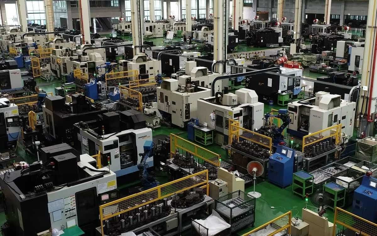
Yes, we are a manufacturer with our own factory.
Common models are in stock, and orders are usually shipped within 1–3 days.
5.Which payment methods are accepted?
We accept T/T, L/C, PayPal, VISA, Western Union, Apple Pay, Google Pay, Afterpay (Clearpay), Klarna, and Trade Assurance.
For full orders: 30% deposit, balance before shipment.
For small/sample orders: full payment in advance.
6.How will you deliver my goods?
We offer flexible shipping options: DHL, UPS, FedEx, TNT, EMS, as well as air or sea freight.
All deliveries ensure door-to-door fast and safe service.
7.How do you inspect and guarantee your products?
All products are tested before shipment to ensure perfect working condition.
We offer a 12-month warranty — if a product fails due to quality issues, we provide free spare parts or repair support.
8.What about after-sales service?
If you encounter any problem during use, please contact your sales manager or our support team at any time.
We will respond quickly and help solve the issue efficiently.
9.What are your main applications?
- Hydraulic systems
- Agricultural machinery
- Construction machinery
- Automobile industry
- Local distributors and maintenance centers
10.Can I get a discount for bulk orders?
Yes. We offer competitive wholesale prices and try our best to give benefits to long-term partners.
Shoot Us An Email
Professional Manufacturer