
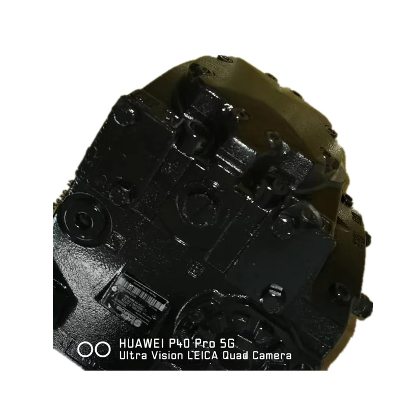
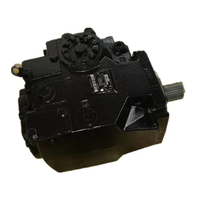


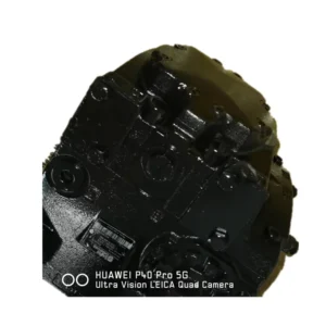

Product Overview
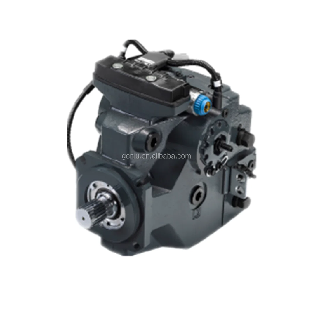
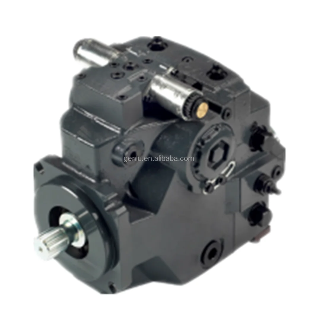
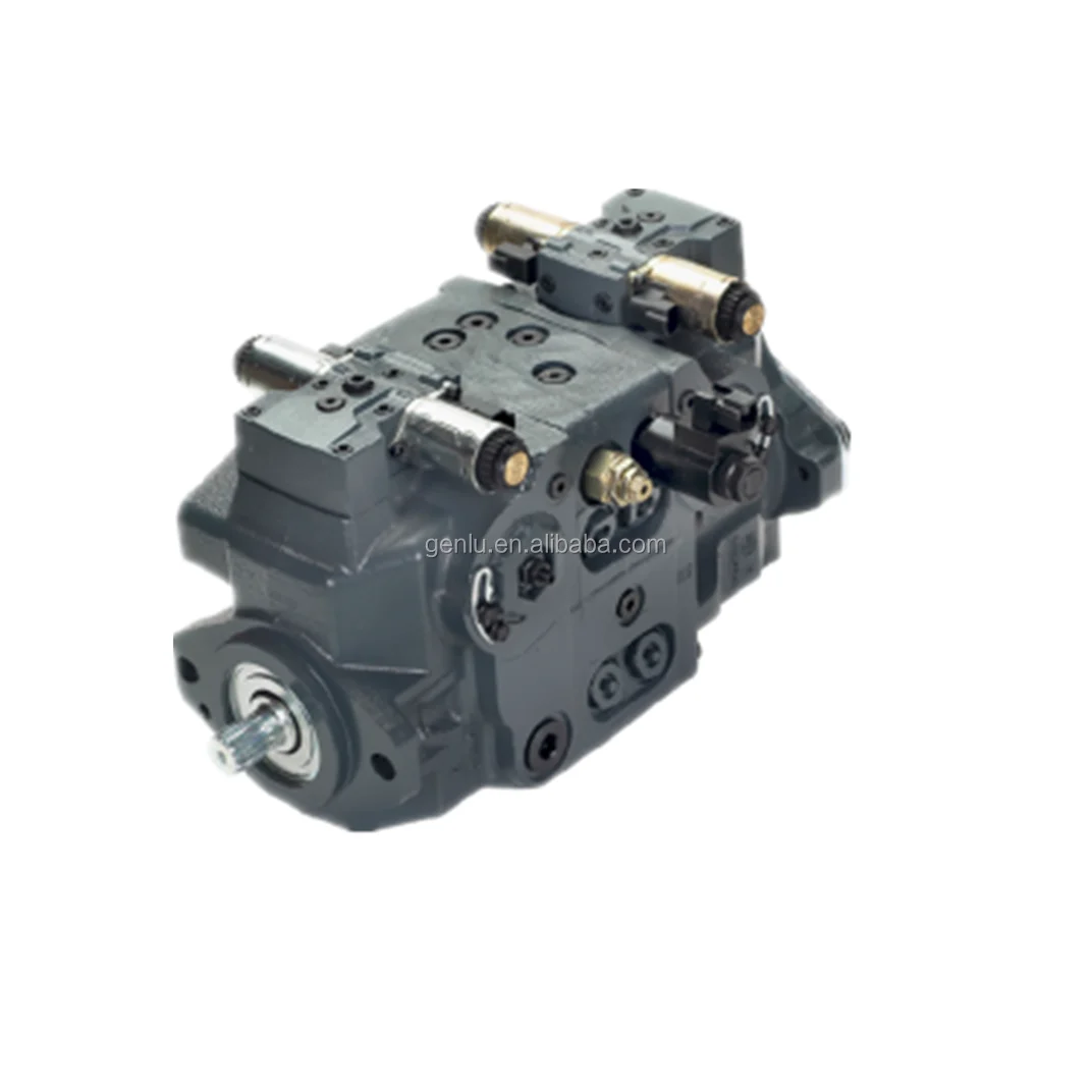
The H1P130RBAA5C2ND4GG3H3L42 (Material No. 83023779) and H1P100LBAA5C2ND3HG9NNL42 (Material No. 83051971) are the 130 cc-class and 100 cc-class core models within the Danfoss H1P series of closed-circuit variable displacement axial piston pumps. The H1P series employs a cradle swashplate design, serving as a pioneer platform in the closed-circuit variable piston pump segment, with displacements spanning 45–280 cm³/rev across 15 specifications, maximum working pressure up to 450 bar, and peak pressure of 480 bar.
The H1P series is renowned for high total efficiency, compact lightweight design, and extensive control options. Pump output flow is proportional to input speed and displacement, with displacement infinitely adjustable between zero and maximum. Flow direction can be reversed by simply tilting the swashplate to the opposite side of its zero-displacement position. The series can be used with any Danfoss hydraulic motor to form a complete closed-circuit hydraulic system.
H1P Series Core Features: Designed for quality and reliability; wide range of controls (EDC, FNR, NFPE, AC, FDC, MDC, HDC); high total efficiency; compact, lightweight, and length optimized; standardized connector interface; PLUS+1® compliant control and sensor options; integral filtration available with integrated filter bypass sensors and switch.
Model Code Breakdown (for procurement and engineering reference):
H1P130RBAA5C2ND4GG3H3L42 (Material No. 83023779):
H1P130: H1P series, nominal size 130, geometric displacement 130.0 cm³/rev
R: Rotation direction, right-hand (clockwise, viewed from shaft end)
B: Product version B
A: Port configuration, ANSI O-ring boss port configuration
A5: Control type code
C2: Orifice configuration
N: No displacement limiters
D4: Endcap type
G: Mounting flange code
G3: Input shaft code
H3: Auxiliary mounting pad code
L42: Protection type and pressure setting code
H1P100LBAA5C2ND3HG9NNL42 (Material No. 83051971):
H1P100: H1P series, nominal size 100, geometric displacement 101.7 cm³/rev
L: Rotation direction, left-hand (counterclockwise, viewed from shaft end)
B: Product version B
A: Port configuration, ANSI O-ring boss port configuration
A5: Control type code
C2: Orifice configuration
N: No displacement limiters
D3: Endcap type
H: Mounting flange code
G9: Input shaft code
NN: No auxiliary mounting pad
L42: Protection type and pressure setting code
Drop-in Replacement Advantage: Manufactured to exact Danfoss OEM specifications, these pumps achieve complete drop-in interchangeability with the original H1P series for ISO 3019-1 mounting flange, shaft dimensions (ANSI B92.1 splined shaft), SAE main port layout, and control module interface. Every pump undergoes 100% simulated load testing prior to shipment, validating 450 bar pressure loading, control response, and volumetric efficiency under conditions replicating real-world duty cycles.
Technical Specifications
H1P130 Series General Specifications:
Series: Danfoss H1P Series (Closed Circuit, Cradle Swashplate Design)
Nominal Size: 130
Geometric Displacement: 130.0 cm³/rev (7.93 in³/rev)
Rated Working Pressure: 380–450 bar (5511–6527 psi)
Maximum Working Pressure: 450 bar (6528 psi)
Peak Pressure: 480 bar (6960 psi)
Rated Speed: 3200 rpm
Maximum Speed: 3400 rpm
Minimum Speed: 500 rpm
Theoretical Flow (at rated speed): 419 L/min (111 US gal/min)
Mounting Flange: SAE D 4-bolt flange
Shaft: ANSI B92.1 splined shaft
Housing Material: High-strength cast iron
Seal Material: NBR (nitrile rubber)
Weight (without PTO and filter): 83 kg (187 lb)
Control Options: EDC, FNR, NFPE, AC, FDC, MDC, HDC
H1P130RBAA5C2ND4GG3H3L42:
Model Code: H1P130RBAA5C2ND4GG3H3L42
Material Number: 83023779
Rotation: Right-hand (clockwise)
Geometric Displacement: 130.0 cm³/rev
Rated Working Pressure: 450 bar
Peak Pressure: 480 bar
Mounting Flange: SAE D 4-bolt flange
H1P100 Series General Specifications:
Series: Danfoss H1P Series (Closed Circuit, Cradle Swashplate Design)
Nominal Size: 100
Geometric Displacement: 101.7 cm³/rev (6.21 in³/rev)
Rated Working Pressure: 450 bar (6527 psi)
Peak Pressure: 480 bar (6960 psi)
Rated Speed: 3300 rpm
Maximum Speed: 3800 rpm
Theoretical Flow (at rated speed): 335 L/min (88.5 US gal/min)
Mounting Flange: SAE C 4-bolt flange
Shaft: ANSI B92.1 splined shaft
Housing Material: High-strength cast iron
Seal Material: NBR (nitrile rubber)
Weight (without PTO and filter): 62 kg (137 lb)
Control Options: EDC, FNR, NFPE, AC, FDC, MDC, HDC
H1P100LBAA5C2ND3HG9NNL42:
Model Code: H1P100LBAA5C2ND3HG9NNL42
Material Number: 83051971
Rotation: Left-hand (counterclockwise)
Geometric Displacement: 101.7 cm³/rev
Rated Working Pressure: 450 bar
Peak Pressure: 480 bar
Mounting Flange: SAE C 4-bolt flange
H1P Series Displacement Size Reference:
H1P 045/053: 45.0–53.8 cm³/rev, max 380–420 bar, rated 3400 rpm, flow 153–183 L/min, SAE B
H1P 060/068: 60.4–68.0 cm³/rev, max 380–420 bar, rated 3500 rpm, flow 210–238 L/min, SAE C
H1P 069/078: 69.2–78.1 cm³/rev, max 450 bar, rated 3500 rpm, flow 243–273 L/min, SAE C
H1P 089/100: 89.2–101.7 cm³/rev, max 450 bar, rated 3300 rpm, flow 294–335 L/min, SAE C
H1P 115/130: 115.2–130.0 cm³/rev, max 450 bar, rated 3200 rpm, flow 371–419 L/min, SAE D
H1P 147/165: 147.2–165.1 cm³/rev, max 450 bar, rated 3000 rpm, flow 441–495 L/min, SAE D
H1P 210/250/280: 211.5–280.2 cm³/rev, max 420–450 bar, rated 2600 rpm, flow 549–728 L/min, SAE E
Key Technical Advantages
1. Cradle Swashplate Design with Flow Direction Reversal
The H1P series employs a cradle swashplate axial piston rotary group design with parallel-arranged pistons, achieving variable displacement by altering piston stroke via an angle-adjustable swashplate. Pump flow is proportional to input speed and displacement, with displacement infinitely adjustable between zero and maximum. Flow direction can be reversed by simply tilting the swashplate to the opposite side of its zero-displacement position, eliminating the need for additional directional valves, particularly suitable for closed-circuit hydrostatic travel and swing drive systems.
2. High Total Efficiency with Compact Lightweight Design
The H1P series is renowned for high total efficiency and compact lightweight design. The cradle swashplate design enables the pump to deliver high power output while maintaining a small installation envelope. The H1P130 achieves a displacement of 130 cm³/rev with a weight of only 83 kg; the H1P100 achieves 101.7 cm³/rev with a weight of only 62 kg, leading its displacement class in power density. The length-optimized housing design is particularly suitable for skid steer loaders, trenchers, asphalt pavers, and other mobile hydraulic applications with strict installation space requirements.
3. Extensive Control Options with Flexible Configuration
The H1P series offers an industry-leading combination of control options:
EDC (Electrical Displacement Control): Proportional displacement control via proportional solenoid with 12V/24V supply options and manual override
FNR (Forward-Neutral-Reverse): Solenoid-operated forward/reverse switching using 12 or 24 Vdc solenoid valves to port pressure to either side of the pump servo piston
MDC (Manual Displacement Control): Converts mechanical input to hydraulic signal via spring-centered four-way servo valve; maximum handle input torque only 1.4 N·m
NFPE (Non-Feedback Proportional Electric): Proportional displacement control without position feedback
FDC (Fan Drive Control): Optimized for engine cooling fan drives
AC (Automotive Control): Speed-related automatic regulation
HDC (Hydraulic Displacement Control): Hydraulic pilot signal driven
4. Integrated Charge Pump and Filtration System
The H1P series offers an optional integrated charge pump (e.g., 20/24 cm³/rev), providing cooling and leakage compensation flow for the closed circuit while supplying the pressure oil required for swashplate operation. The charge pressure relief valve setting is typically 20–24 bar. The integral filtration system with integrated filter bypass sensors and switch enables real-time monitoring of filter status to ensure hydraulic system fluid cleanliness.
5. High-Strength Cast-Iron Housing with Long Service Life
The pump body is precision-cast from high-strength cast iron, with the material’s damping characteristics effectively suppressing structural vibration and fluid-borne noise. The H1P series employs precision-ground pistons and cylinder bores with micron-level clearances. The valve plate employs precision lapping with optimized pre-compression and pre-decompression angles, maintaining stable volumetric and mechanical efficiency at 450 bar maximum pressure. The case pressure rating is 3.0 bar rated, 5.0 bar maximum.
6. Standardized Interface with PLUS+1® Compliant Control
The H1P series features standardized connector interfaces and PLUS+1® compliant control and sensor options, enabling seamless integration into modern mobile equipment electronic control systems. Standardized SAE mounting flanges (SAE B through SAE E) and shafts require no adaptation for replacement, significantly reducing equipment downtime.
Application Areas
Skid Steer Loaders: Travel drives and work equipment hydraulic systems (one of the core application areas for the H1P series)
Trenchers: Trench chain drives and travel hydraulic systems
Asphalt Pavers: Travel drives and paving equipment hydraulic systems
Windrowers: Travel drives and work equipment hydraulic systems
Aerial Lifts: Travel drives and boom hydraulic systems
Vibratory Rollers: Vibration and travel drive hydraulic systems
Forestry Machinery: Feller bunchers and forwarders hydraulic drive systems
Construction Equipment: Excavator, bulldozer, and other closed-circuit travel drive systems
Expert Maintenance Tips
1. Hydraulic Fluid Cleanliness
The H1P series control spool operates with extremely tight clearances and is highly sensitive to particulate contamination. System fluid cleanliness must meet ISO 4406 18/15/12 or better. Recommended fluids are ISO VG46 anti-wear mineral hydraulic oils (per DIN 51524 T.2). Install a 10 μm absolute-rated filter element at the pump inlet. Replace elements at 500 hours after first commissioning, then every 1,000 operating hours or 6 months, whichever comes first.
2. EDC Electronic Displacement Controller Maintenance
If equipped with EDC control module, regularly inspect proportional solenoid electrical connectors for corrosion, moisture ingress, or loose pins. EDC control supports 12V/24V supply options; confirm that supply voltage matches solenoid specifications. Verify the control current signal waveform with an oscilloscope every 2,000 hours to ensure proper PWM waveform and accurate displacement control.
3. MDC Manual Displacement Controller Maintenance
The H1P series MDC control module is equipped with a spring-centered four-way servo valve, with maximum handle input torque of only 1.4 N·m. Regularly inspect the linkage mechanism for wear and clearance, ensuring normal operating feel and accurate response. Apply appropriate grease to linkage joints to prevent corrosion and binding. The MDC is equipped with a Neutral Start Switch (NSS); regularly check its function to ensure safe starting.
4. Case Drain Line Requirements
The case drain line must return directly to the reservoir. Maximum permissible back pressure must not exceed specified values. The H1P130/H1P100 case pressure rating is 3.0 bar rated, with a maximum of 5.0 bar. The drain outlet must terminate below oil level at all times to prevent air ingestion. The drain line diameter must not be smaller than the pump case drain port size. Charge pressure should be maintained at approximately 20 bar to ensure proper closed-circuit operation and stable control system performance.
5. Pre-Start Priming and Air Bleeding
Before first start, fill the pump housing with clean hydraulic fluid through the case drain port. After installation, turn the drive shaft by hand several revolutions to confirm free rotation without binding. Position the control at neutral (zero displacement) and run at low speed for 5–10 minutes. Verify continuous bubble-free flow from the case drain. Only after confirming adequate lubrication and charge pressure should the pump be loaded.
6. Integral Filter Maintenance
If equipped with integral filtration, regularly check the filter bypass sensor and switch operating status. Replace the filter element at 500 hours after first commissioning, then every 1,000 operating hours or 6 months, whichever comes first. When replacing the filter, simultaneously inspect the filter housing seal ring condition to ensure no leakage. Integral filtration effectively extends hydraulic fluid and pump service life.