
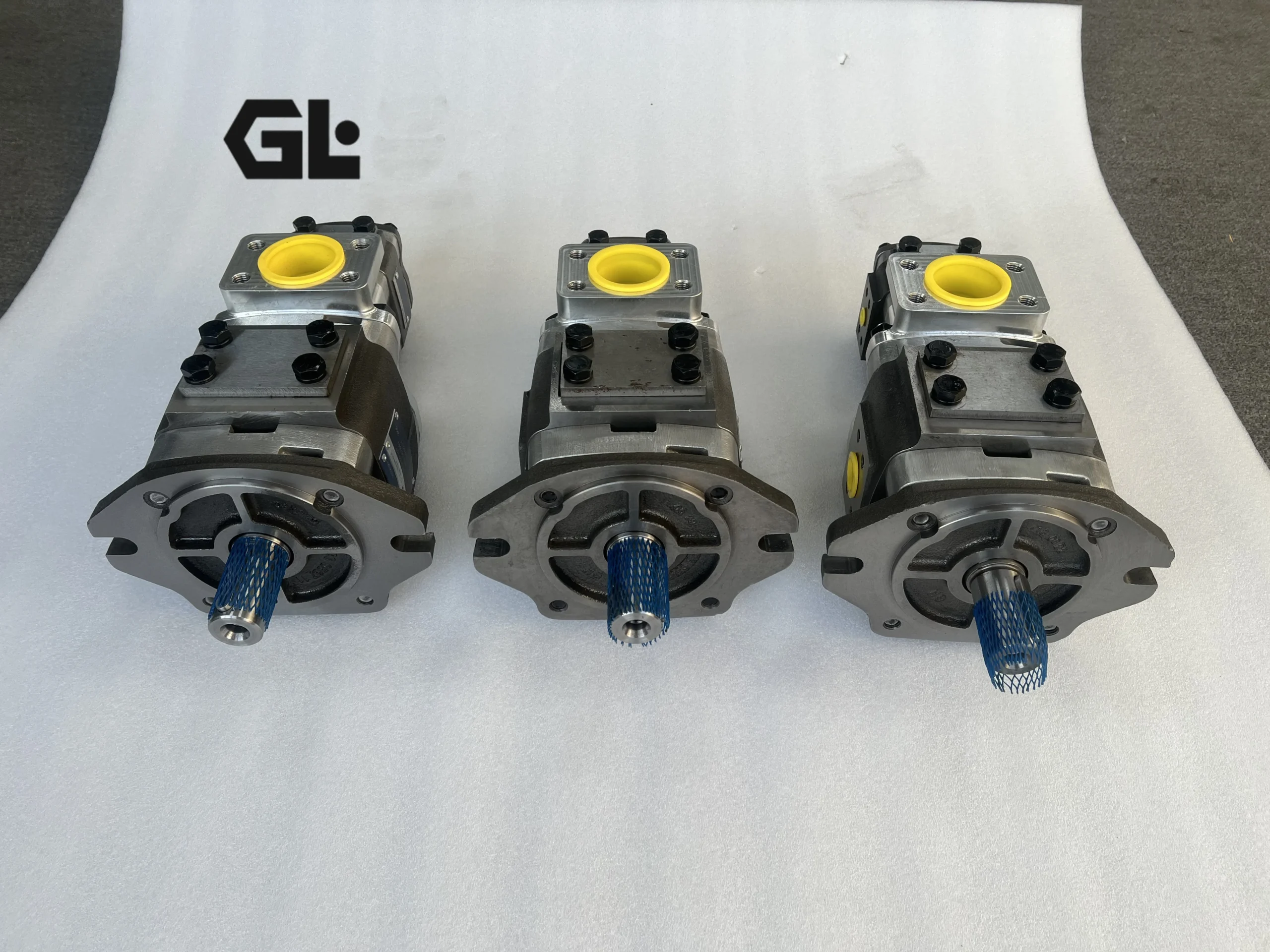

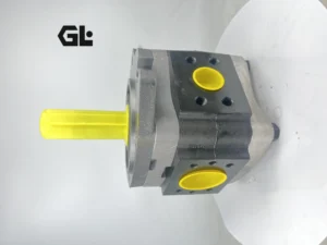

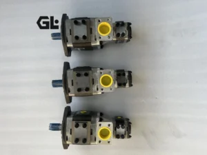
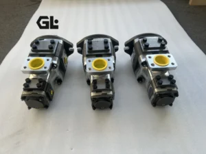
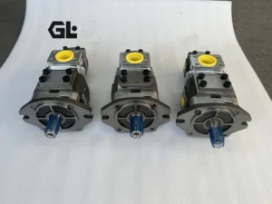
IPN5 IPV IPV3 IPV4 IPV5 IPV6 IPV7 high pressure hydraulic internal gear pump IPV IPN IPN5-64 141 hydraulic oil pump
I. Core Technical Parameters
1. Basic performance parameters
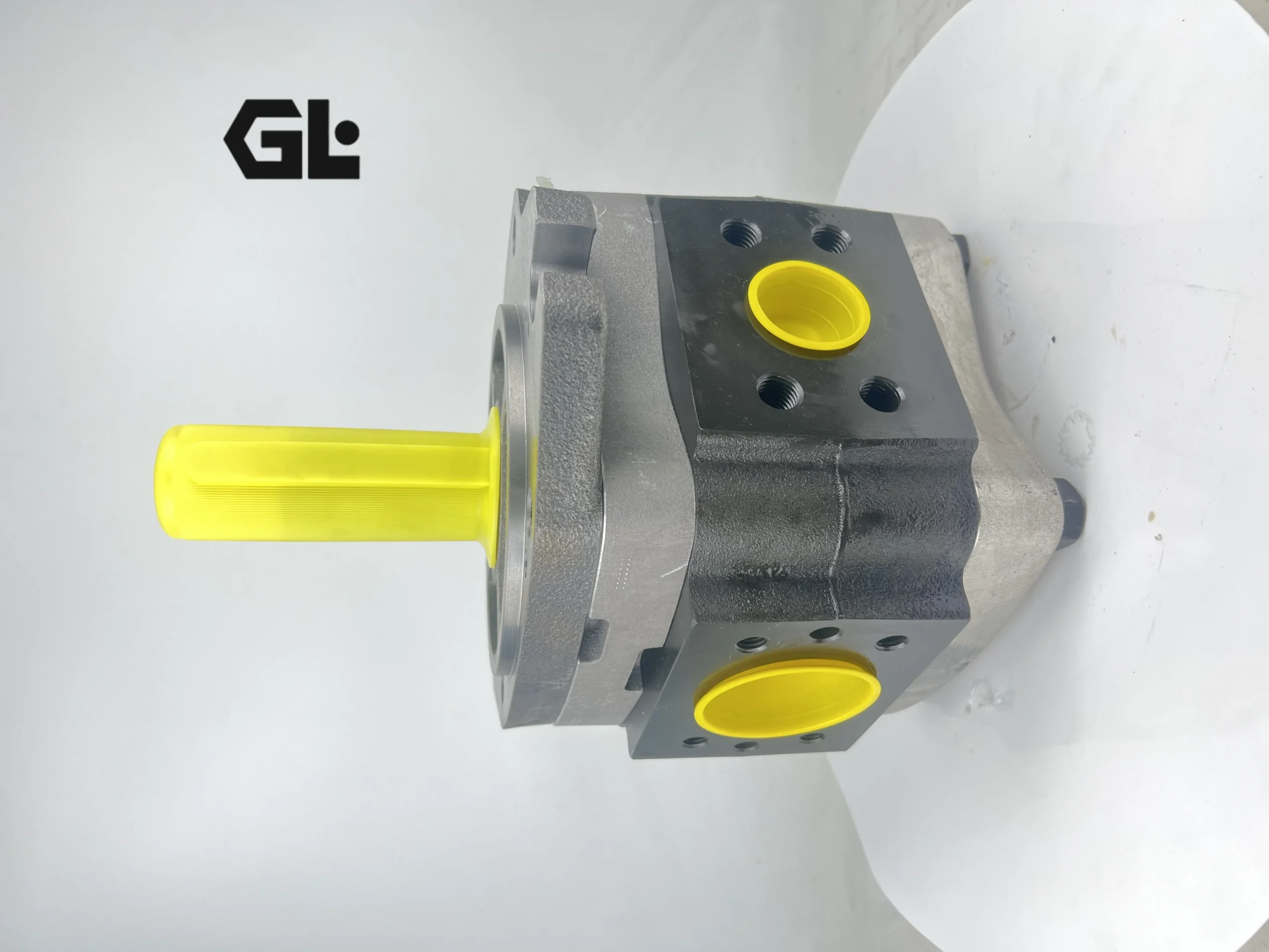
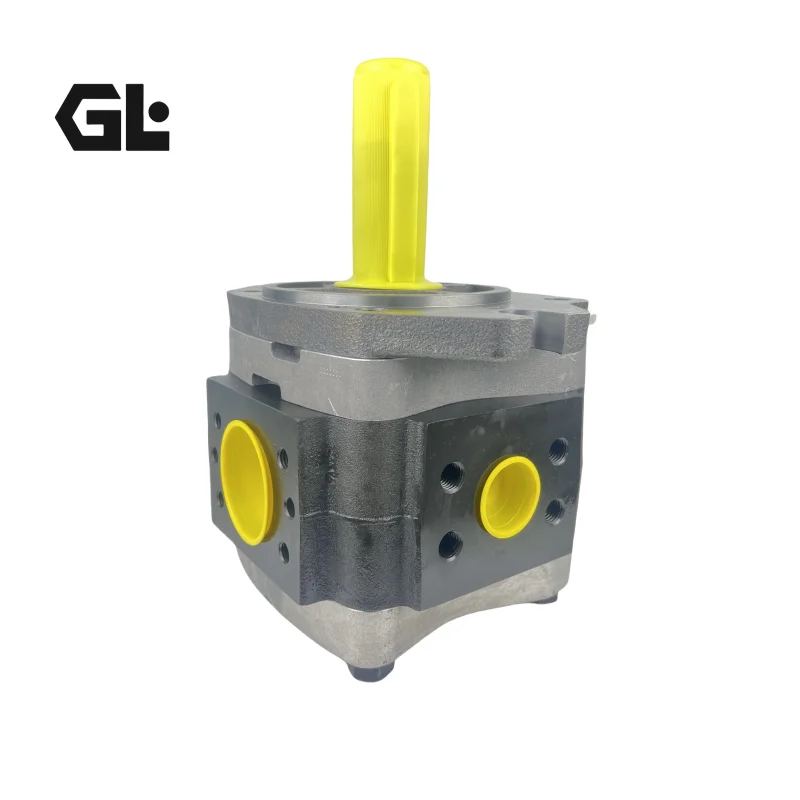
Pump body type: Internal gear pump, fixed displacement type, axial suction/discharge structure, with involute tooth profile design
Displacement parameters: Rated displacement 64 cc/r (the meaning of “64” in the model), theoretical displacement 64 cm³/rev, volumetric efficiency ≥93%, total efficiency ≥85%
Pressure parameters: Continuous working pressure 280 bar, short-term maximum pressure 315 bar (cumulative ≤100 hours), recommended working pressure 140-250 bar
Rotational speed parameters: Rated speed 1500 rpm, maximum speed 2800 rpm, minimum stable speed 300 rpm. When the rotational speed fluctuation is ≤±2%, the flow stability error is ≤1.5%
Flow parameters: The maximum output flow under rated conditions is approximately 96 L/min (64 ml/r×1500 rpm÷1000), the recommended working flow is 60-90 L/min, and the return oil back pressure is ≤0.3 MPa
Power parameters: Continuous output power is approximately 37 kW (280 bar×96 L/min÷60÷100), and the short-term maximum power is 45 kW (315 bar×96 L/min÷60÷100).
2. Structure and connection parameters
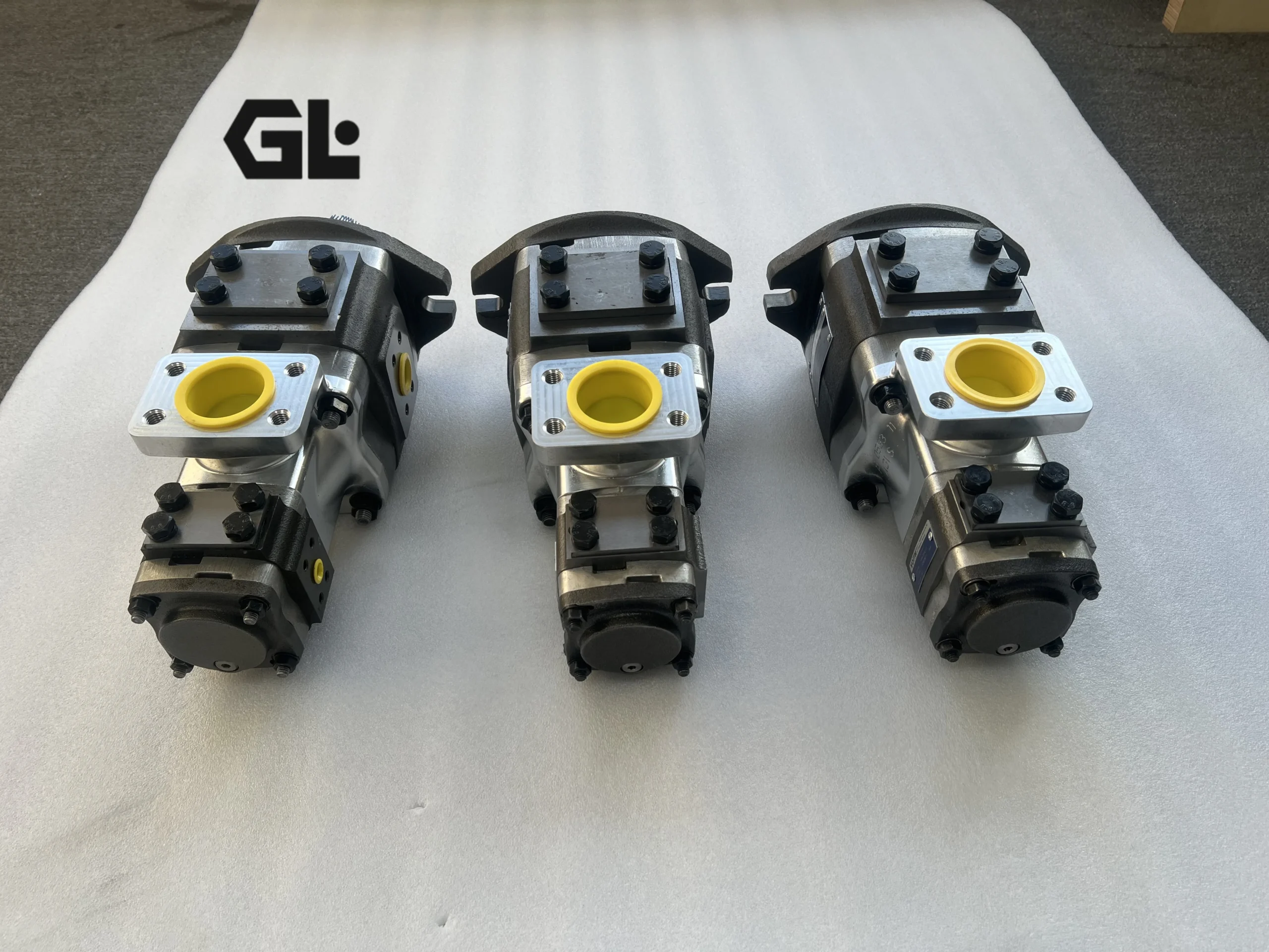
Structural type: High-strength cast iron housing, with internal gears (driving) and external gears (driven) inside. Crescent-shaped plates separate the high and low pressure chambers, and the distribution plate and end cover are designed as an integrated unit
Gear parameters: The internal gear (driving) has 6 teeth, and the external gear (driven) has 7 teeth, forming 7 sealed working chambers. A special tooth profile design is adopted to reduce pulsation
Output shaft specification: Diameter 32mm, flat key connection (8× 7mm), shaft extension length 60mm, capable of withstanding radial force ≤ 800N and axial force ≤ 500N
Installation method: Square flange (106.4× 106.4mm), 4 installation holes (diameter 14mm, hole spacing 82.5mm), installation plane roughness ≤Ra3.2
Oil port specifications: Inlet G1½ (internal thread), outlet G1¼ (internal thread), drain G1/4 (internal thread), all located on the side of the pump body
Shape and weight: The overall dimensions (length × width × height) ≈350×250×240 mm, with a weight of approximately 29 kg. The structure is compact and easy to install
3. Medium and Environmental requirements
Applicable medium: L-HM 46/68 anti-wear hydraulic oil, also compatible with L-HV low-temperature hydraulic oil (operating conditions below -20℃) and L-HS low pour point hydraulic oil
Medium characteristics: Recommended viscosity 15-60 mm²/s, ultimate viscosity range 10-300 mm²/s; Operating temperature: -20 ℃ to 80℃ (continuous), short-term up to 90℃ (≤30 minutes). Moisture content ≤0.05%, and the degree of solid particle contamination shall reach ISO 4406 17/14 grade
Environmental conditions: Protection grade IP65, suitable for industrial environments with humidity ≤95% (no condensation); The altitude is ≤2000 meters. In high-altitude areas, the usage limit should be reduced. Vibration tolerance acceleration ≤ 8g, noise level ≤ 82dB (at 1 meter)Ii. Working Principle
1. Basic working mechanism
IPN5-64 141 adopts the working principle of an internal gear pump and realizes the conversion of hydraulic energy based on the mechanism of “volume change + distribution control”.
Structural basis: Inside the pump body, there is a pair of special gear pairs. The internal gear (rotor) and the external gear (stator) are eccentrically arranged, and the crescent-shaped plate separates the two into the oil suction chamber and the oil pressure chamber
Energy conversion process
Oil suction stage: When the motor drives the internal gear to rotate, the internal gear drives the external gear to rotate in the same direction. In the oil suction zone, the gear teeth gradually disengage from meshing, the volume of the sealed cavity increases to form a negative pressure, and the oil is sucked in from the oil inlet
Oil transmission: The oil that has been sucked in fills the space between the teeth and is carried to the oil pressure area as the gears rotate
During the oil pressing stage: In the oil pressing zone, the gear teeth remesh, the volume of the sealed cavity decreases, and the oil is squeezed out from the oil outlet
Flow distribution control: The crescent-shaped plate is fixed on the pump body to ensure complete isolation between the suction chamber and the pressure chamber, preventing direct communication between high and low pressure oil
2. Principles of flow and pressure generation
Traffic generation
Each time the pump rotates once, each sealed cavity completes one process of oil suction and pressure
The theoretical flow calculation formula is: Q₀ = V × n ÷ 1000 (L/min), where V is the displacement (cc/r) and n is the rotational speed (rpm).
Actual flow rate: Q = Q₀ × ηv, where ηv represents volumetric efficiency (≥93%), mainly affected by gear meshing clearance leakage
Pressure generation
The output pressure depends on the system load. When the load increases, the output pressure rises accordingly
The maximum working pressure of the pump is limited by the strength of the pump body, the bearing capacity and the sealing performance (280 bar).
Pressure pulsation control: The specially designed 7-tooth structure ensures that the flow pulsation rate is ≤2% (tested under 280 bar conditions), significantly reducing system vibration and noise
1. Basic performance parameters
Pump body type: Internal gear pump, fixed displacement type, axial suction/discharge structure, with involute tooth profile design
Displacement parameters: Rated displacement 64 cc/r (the meaning of “64” in the model), theoretical displacement 64 cm³/rev, volumetric efficiency ≥93%, total efficiency ≥85%
Pressure parameters: Continuous working pressure 280 bar, short-term maximum pressure 315 bar (cumulative ≤100 hours), recommended working pressure 140-250 bar
Rotational speed parameters: Rated speed 1500 rpm, maximum speed 2800 rpm, minimum stable speed 300 rpm. When the rotational speed fluctuation is ≤±2%, the flow stability error is ≤1.5%
Flow parameters: The maximum output flow under rated conditions is approximately 96 L/min (64 ml/r×1500 rpm÷1000), the recommended working flow is 60-90 L/min, and the return oil back pressure is ≤0.3 MPa
Power parameters: Continuous output power is approximately 37 kW (280 bar×96 L/min÷60÷100), and the short-term maximum power is 45 kW (315 bar×96 L/min÷60÷100).
2. Structure and connection parameters
Structural type: High-strength cast iron housing, with internal gears (driving) and external gears (driven) inside. Crescent-shaped plates separate the high and low pressure chambers, and the distribution plate and end cover are designed as an integrated unit
Gear parameters: The internal gear (driving) has 6 teeth, and the external gear (driven) has 7 teeth, forming 7 sealed working chambers. A special tooth profile design is adopted to reduce pulsation
Output shaft specification: Diameter 32mm, flat key connection (8× 7mm), shaft extension length 60mm, capable of withstanding radial force ≤ 800N and axial force ≤ 500N
Installation method: Square flange (106.4× 106.4mm), 4 installation holes (diameter 14mm, hole spacing 82.5mm), installation plane roughness ≤Ra3.2
Oil port specifications: Inlet G1½ (internal thread), outlet G1¼ (internal thread), drain G1/4 (internal thread), all located on the side of the pump body
Shape and weight: The overall dimensions (length × width × height) ≈350×250×240 mm, with a weight of approximately 29 kg. The structure is compact and easy to install
3. Medium and Environmental requirements
Applicable medium: L-HM 46/68 anti-wear hydraulic oil, also compatible with L-HV low-temperature hydraulic oil (operating conditions below -20℃) and L-HS low pour point hydraulic oil
Medium characteristics: Recommended viscosity 15-60 mm²/s, ultimate viscosity range 10-300 mm²/s; Operating temperature: -20 ℃ to 80℃ (continuous), short-term up to 90℃ (≤30 minutes). Moisture content ≤0.05%, and the degree of solid particle contamination shall reach ISO 4406 17/14 grade
Environmental conditions: Protection grade IP65, suitable for industrial environments with humidity ≤95% (no condensation); The altitude is ≤2000 meters. In high-altitude areas, the usage limit should be reduced. Vibration tolerance acceleration ≤ 8g, noise level ≤ 82dB (at 1 meter)Ii. Working Principle
1. Basic working mechanism
IPN5-64 141 adopts the working principle of an internal gear pump and realizes the conversion of hydraulic energy based on the mechanism of “volume change + distribution control”.
Structural basis: Inside the pump body, there is a pair of special gear pairs. The internal gear (rotor) and the external gear (stator) are eccentrically arranged, and the crescent-shaped plate separates the two into the oil suction chamber and the oil pressure chamber
Energy conversion process
Oil suction stage: When the motor drives the internal gear to rotate, the internal gear drives the external gear to rotate in the same direction. In the oil suction zone, the gear teeth gradually disengage from meshing, the volume of the sealed cavity increases to form a negative pressure, and the oil is sucked in from the oil inlet
Oil transmission: The oil that has been sucked in fills the space between the teeth and is carried to the oil pressure area as the gears rotate
During the oil pressing stage: In the oil pressing zone, the gear teeth remesh, the volume of the sealed cavity decreases, and the oil is squeezed out from the oil outlet
Flow distribution control: The crescent-shaped plate is fixed on the pump body to ensure complete isolation between the suction chamber and the pressure chamber, preventing direct communication between high and low pressure oil
2. Principles of flow and pressure generation
Traffic generation
Each time the pump rotates once, each sealed cavity completes one process of oil suction and pressure
The theoretical flow calculation formula is: Q₀ = V × n ÷ 1000 (L/min), where V is the displacement (cc/r) and n is the rotational speed (rpm).
Actual flow rate: Q = Q₀ × ηv, where ηv represents volumetric efficiency (≥93%), mainly affected by gear meshing clearance leakage
Pressure generation
The output pressure depends on the system load. When the load increases, the output pressure rises accordingly
The maximum working pressure of the pump is limited by the strength of the pump body, the bearing capacity and the sealing performance (280 bar).
Pressure pulsation control: The specially designed 7-tooth structure ensures that the flow pulsation rate is ≤2% (tested under 280 bar conditions), significantly reducing system vibration and noise
Iii. Product Features and Advantages
1. Performance advantages
High volumetric efficiency: By adopting advanced axial and radial pressure compensation technology, the volumetric efficiency can reach over 93%, which is 5-8% higher than that of ordinary gear pumps, reducing energy loss
Low flow pulsation: The specially designed 7-tooth structure and optimized crescent-shaped plate keep the flow pulsation rate below 2% (test pressure 280 bar), significantly reducing system vibration and noise and extending equipment lifespan
Wide viscosity adaptability: It can convey media with a viscosity range of 10-300 mm²/s, especially suitable for high-viscosity hydraulic oil and grease, expanding application scenarios
Strong self-priming ability: It can achieve self-priming without an auxiliary pump, with an oil suction height of up to 500mm and an oil suction port vacuum degree of -0.03MPa, reducing system configuration and costs
2. Structural advantages
Compact and lightweight: The overall weight is only 29 kg, with a small volume (350×250×240 mm), making it easy to install on equipment with limited space
High reliability: The high-strength cast iron housing and precisely machined gear pairs have strong impact resistance, with an average mean time between failures of ≥ 15,000 hours, making it suitable for harsh industrial environments
Easy maintenance: Modular design allows the main components (gear pairs, distribution plates) to be disassembled and replaced separately, reducing maintenance time by 50% and lowering maintenance costs
Strong anti-pollution ability: Compared with plunger pumps and vane pumps, it is less sensitive to oil contamination and is suitable for polluting environments such as construction machinery, extending the oil replacement cycle
3. Control advantage
Smooth output feature: Low pulsation output (≤2%) enables the actuator to operate more smoothly, making it particularly suitable for hydraulic systems with high precision requirements, such as injection molding machine clamping devices and precision processing equipment
Bidirectional rotation capability: It can operate in both forward and reverse directions, outputting the same torque and flow rate, and is suitable for applications that require bidirectional drive, such as coiling machines and uncoiling machines
Low-noise operation: Optimized gear parameters and housing structure keep the noise below 82 dB, improving the working environment and reducing the fatigue of operators
Strong adaptability: It has good adaptability to oil temperature changes, a wide working temperature range (-20℃ to 80℃), and is suitable for different regions and working conditions
Iv. Usage Functions and Purposes
1. Core functions
Hydraulic energy conversion: Convert the mechanical energy of the prime mover (motor or engine) into the pressure energy of the hydraulic system, providing a stable high-pressure oil source (up to 280 bar)
Fluid transportation: As a transfer pump, it can transport liquids with lubricity, especially suitable for viscous media such as hydraulic oil, lubricating oil and fuel oil
Flow control: By adjusting the input speed or the system relief valve, the output flow can be precisely controlled to meet the requirements of different working conditions
Pressure stability: When the load changes, it can maintain a relatively stable output pressure, protecting the system from overload damage and enhancing system reliability
2. Main uses
Industrial hydraulic systems: main or auxiliary pumps for injection molding machines, die-casting machines, presses, machine tools, etc., providing power and controlling pressure
Construction machinery: Hydraulic systems for working devices such as excavators, loaders, and bulldozers, providing lifting, tilting, and traveling power
Agricultural machinery: Hydraulic systems of combine harvesters, tractors, seeders, etc., driving headers, conveying devices and hydraulic accessories
Ship and Ocean Engineering: Hydraulic power sources for deck machinery such as steering gear systems, anchor winches, and hoists
Lubrication system: Centralized lubrication system for large equipment, providing a stable supply of lubricating oil to ensure good lubrication of each friction pair
Petrochemical industry: Transporting viscous media such as crude oil, lubricating oil and fuel oil, as well as metering and proportioning in chemical processes
V. Applicable Machines and Scenarios
1. Industrial application scenarios
Hydraulic system of injection molding machine
Working pressure: 200-280 bar, flow rate: 70-90 L/min
Applied to mold locking and injection systems, it provides high-pressure stable power (mold locking pressure 250-280 bar, injection pressure 200-250 bar)
The low pulsation feature ensures injection accuracy, with energy-saving effects reaching 10-15%. During the pressure-holding stage, it automatically compensates for leakage to maintain pressure stability
Die-casting machine clamping device
Working pressure: 220-280 bar, flow rate: 60-80 L/min
Provide clamping force (1000-3000 tons) and injection power to ensure the mold closes tightly and prevent the leakage of molten metal
High-precision control ensures the dimensional accuracy of die-castings, and high reliability guarantees the continuity of production
Machine tool hydraulic system
Working pressure: 140-200 bar, flow rate: 30-50 L/min
It is used for worktable movement, tool feed and clamping devices, and requires smooth and low-noise operation
Low flow pulsation (≤2%) ensures processing accuracy, extends tool life and reduces operator fatigue
2. Construction machinery scenarios
Excavator working device
Working pressure: 180-280 bar, flow rate: 80-100 L/min
DR Control can simultaneously drive the boom, boom and bucket. It can automatically allocate flow according to the load to ensure coordinated actions
When excavating under heavy load, it outputs high pressure and large flow rate. When moving under light load, it automatically reduces the displacement, lowering energy consumption by approximately 15%
Loader hydraulic system
Working pressure: 160-240 bar, flow rate: 70-90 L/min
Provide power for bucket lifting (pressure 200-240 bar) and tilting (pressure 180-220 bar)
It has strong anti-pollution ability, can adapt to the harsh environment of construction sites, and ensures the continuous operation of equipment
IPV3-3.5-101 、IPV3-5-101 、IPV3-6.3-101 、IPV3-8-101 、IPV3-10-101
IPV4-13-171 、IPV4-16-171 、IPV4-20-171 、IPV4-25-171 、IPV4-32-171
IPVP5-32-101 、IPVP5-40-101 、IPVP5-50-101 、IPVP5-64-101
IPVP6-64-101 、IPVP6-80-101 、IPVP6-100-101 、IPVP6-125-101
IPVP4-13-171 、IPVP4-16-171 、IPVP4-20-171 、IPVP4-25-171
IPV5-32-101 、IPV5-40-101 、IPV5-50-101 、IPV5-64-101、IPVP4-32-171
IPV6-64-101 、IPV6-80-101 、IPV6-100-101 、IPV6-125-101
IPV7-125-101 、IPV7-160-101 、IPV7-200-101 、IPV7-250-101
IPVP3-3.5-101 、IPVP3-5-101 、IPVP3-6.3-101 、IPVP3-8-101 、IPVP3-10-101
IPVP7-125-111 、IPVP7-160-111 、IPVP7-200-111 、IPVP7-250-111
Six. Similar models
1. Different specifications and models of the same series
IPN5-40: Displacement 40 cc/r, continuous working pressure 280 bar, continuous torque approximately 120 Nm, continuous power about 20 kW, smaller in size (about 25 kg), suitable for small hydraulic systems and equipment with limited space
IPN5-50: Displacement 50.3cc /r, continuous working pressure 280 bar, continuous flow rate approximately 75 L/min (at 1500 rpm), continuous power approximately 30 kW. It is suitable for medium-sized hydraulic systems, such as medium-sized injection molding machines and die-casting machines
IPN5-80: Displacement 80 cc/r, continuous working pressure 250 bar, continuous flow rate approximately 120 L/min (at 1500 rpm), continuous power about 40 kW. It is suitable for large hydraulic systems, such as large construction machinery and heavy machine tools
2. Different series models of the same type
IPV5-64 series: With the same displacement as IPN5-64, it adopts a different bearing design and sealing structure. The maximum working pressure can reach 315 bar, and the volumetric efficiency is slightly higher (≥94%), making it suitable for high-pressure working conditions
IPVP5-64 series: Variable type with pressure compensation function, which can automatically adjust the displacement according to the system pressure, achieving remarkable energy-saving effects (20-30%). It is particularly suitable for hydraulic systems with large load variations, such as excavators and injection molding machines
IPH5-64 series: Made of high-strength materials and through special heat treatment processes, it can achieve a maximum working pressure of 330 bar and is suitable for ultra-high pressure hydraulic systems, such as hydraulic presses and extrusion equipment
Vii. Precautions for Use
1. Installation points
Correct positioning: The installation plane must be flat (flatness ≤ 0.05mm), ensuring that the pump shaft and the drive shaft are coaxial (coaxiality ≤ 0.08mm). Elastic couplings should be used for connection. Rigid connection is strictly prohibited to avoid additional radial force (≤ 800N) and axial force (≤ 500N) acting on the pump shaft, otherwise it will cause premature damage to the bearings
Pipeline design
Suction pipe: Select a short straight pipe with an inner diameter of ≥ 40mm (length ≤ 1.0m), reduce elbows, install a 100-mesh coarse filter at a distance of ≥ 200mm from the bottom of the oil tank, ensure suction resistance ≤ 0.03MPa, and prevent cavitation
Oil pressure pipe: Inner diameter ≥ 25mm, with fixed supports (spacing ≤ 500mm) to prevent vibration and wear. An exhaust valve should be installed at the highest point to expel system air
Drain oil pipe: Connected separately to the oil tank and not shared with other pipelines. Pipe diameter ≥ 10mm to ensure smooth oil return, back pressure ≤ 0.05MPa, and prevent shaft seal leakage
Rotation direction: Rotate strictly in the direction indicated by the arrow on the pump body (clockwise when viewed from the shaft end). Reverse rotation can lead to incorrect flow distribution, poor lubrication and pump damage
2. Startup and Operation
Startup program
Before the first start-up, check the oil level, fill the pump with clean hydraulic oil, and manually turn the pump 2 to 3 times to confirm there is no jamming
Jog to start and confirm that the rotation direction is correct
Run without load for 5 to 10 minutes. Wait until the oil temperature rises above 30℃ before gradually loading
The loading process should be smooth. Each pressure increase should be no more than 50 bar, with an interval of no less than 2 minutes. Sudden loading to the rated pressure is strictly prohibited
Operation monitoring
Temperature: The normal operating temperature is 40-60℃, and the maximum should not exceed 70℃. If the temperature rises sharply by more than 15℃ for 10 minutes, the machine should be shut down for inspection. This may be due to improper oil viscosity, insufficient cooling or internal wear
Pressure: It must not exceed the rated pressure of 280 bar, and the fluctuation range should be controlled within ±5 bar. Abnormal fluctuations should be stopped for inspection, which may be due to system leakage or sudden load changes
Noise: When running smoothly, the noise should be uniform. If whistling or abnormal vibration occurs, stop the machine immediately for inspection. It may be due to cavitation, bearing damage or oil contamination
Leakage: Regularly inspect the shaft seal and pipe joints. A trace amount of leakage (≤1.0 mL/h) is allowed. If the leakage volume suddenly increases, it should be dealt with promptly
3. Maintenance and care
Daily maintenance
Check the oil level, oil temperature, oil pressure and leakage every 50 hours of operation, and record the parameters
Check the filter every 200 hours and replace or clean it if necessary (it is recommended to test the oil contamination level at the same time).
Change the hydraulic oil every 1000 hours, thoroughly clean the oil tank and filter, and check that the contamination degree of the oil should reach ISO 4406 17/14 grade
Check the wear of the key components inside the pump (gears, crescent plates, distribution plates) every 2,000 hours and replace them if necessary
Oil and fluid management
Strictly control oil contamination, conduct regular inspections (every 500 hours), and replace and clean the system immediately when the contamination level exceeds the standard
Compatibility tests must be conducted before mixing hydraulic oils of different brands to prevent the reaction of additives and the formation of sediment
In cold regions, the oil should be preheated to above 10℃ before starting in winter (this can be achieved through no-load operation or system circulation) to prevent excessive viscosity of the oil due to low temperatures and damage to the pump
4. Special Precautions
Prevent dry running: It is strictly prohibited to start or operate without oil. Even a brief dry run (>5 seconds) can cause the gears to malfunction