


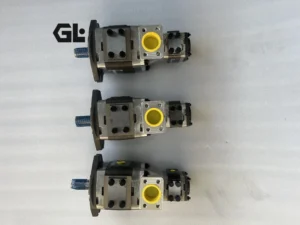
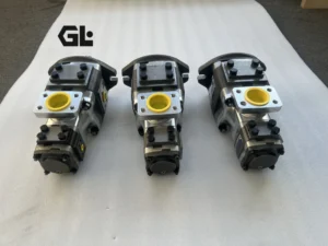
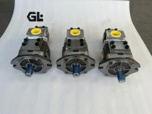
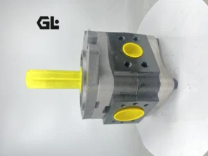
IPS 6-80 101 High Pressure Internal Gear Pump Hydraulic IPV IPS IPS4 IPS5 IPS6 IPS7 IPV3 IPV4 IPV5 IPV6 IPV7 Oil Pump
I. Core Technical Parameters
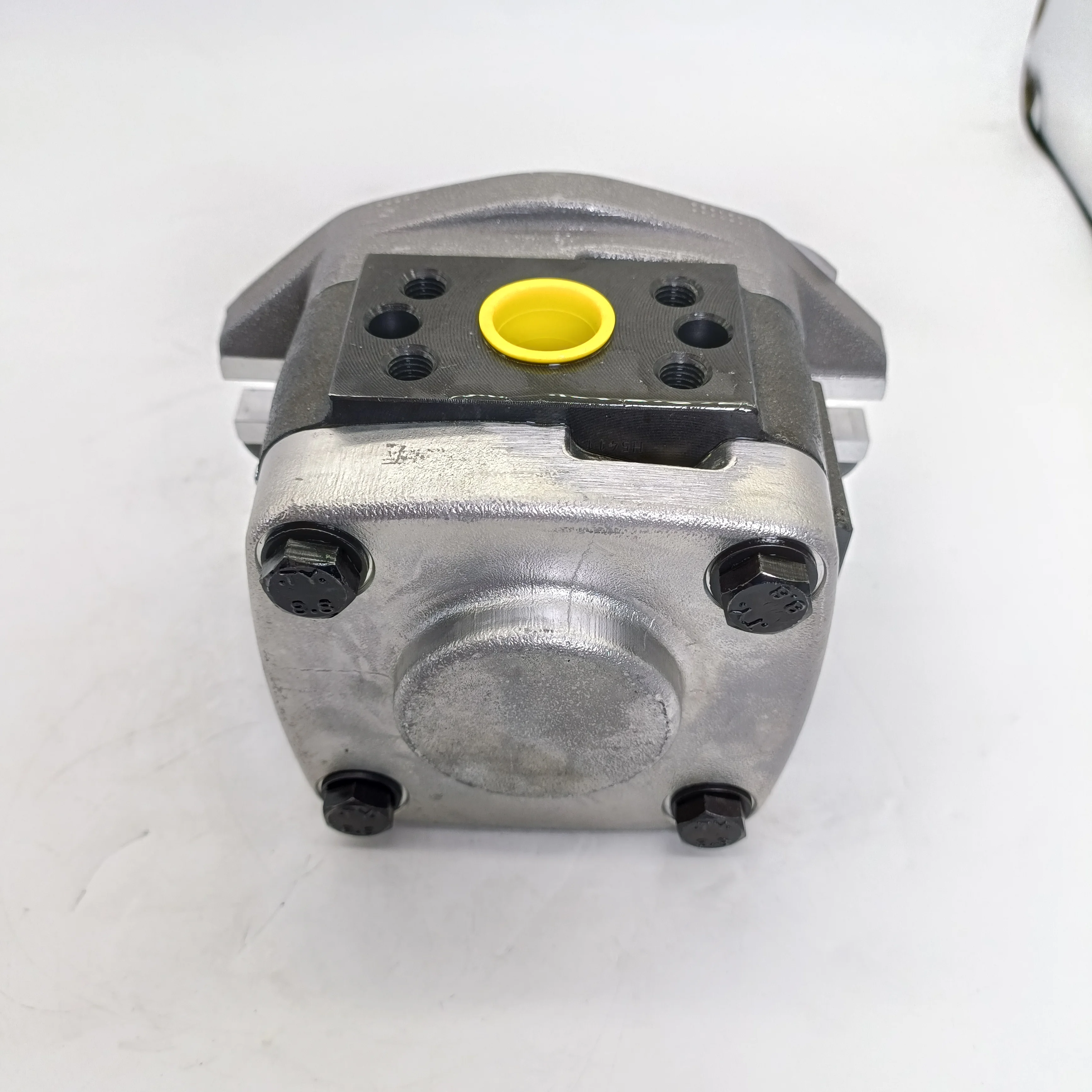
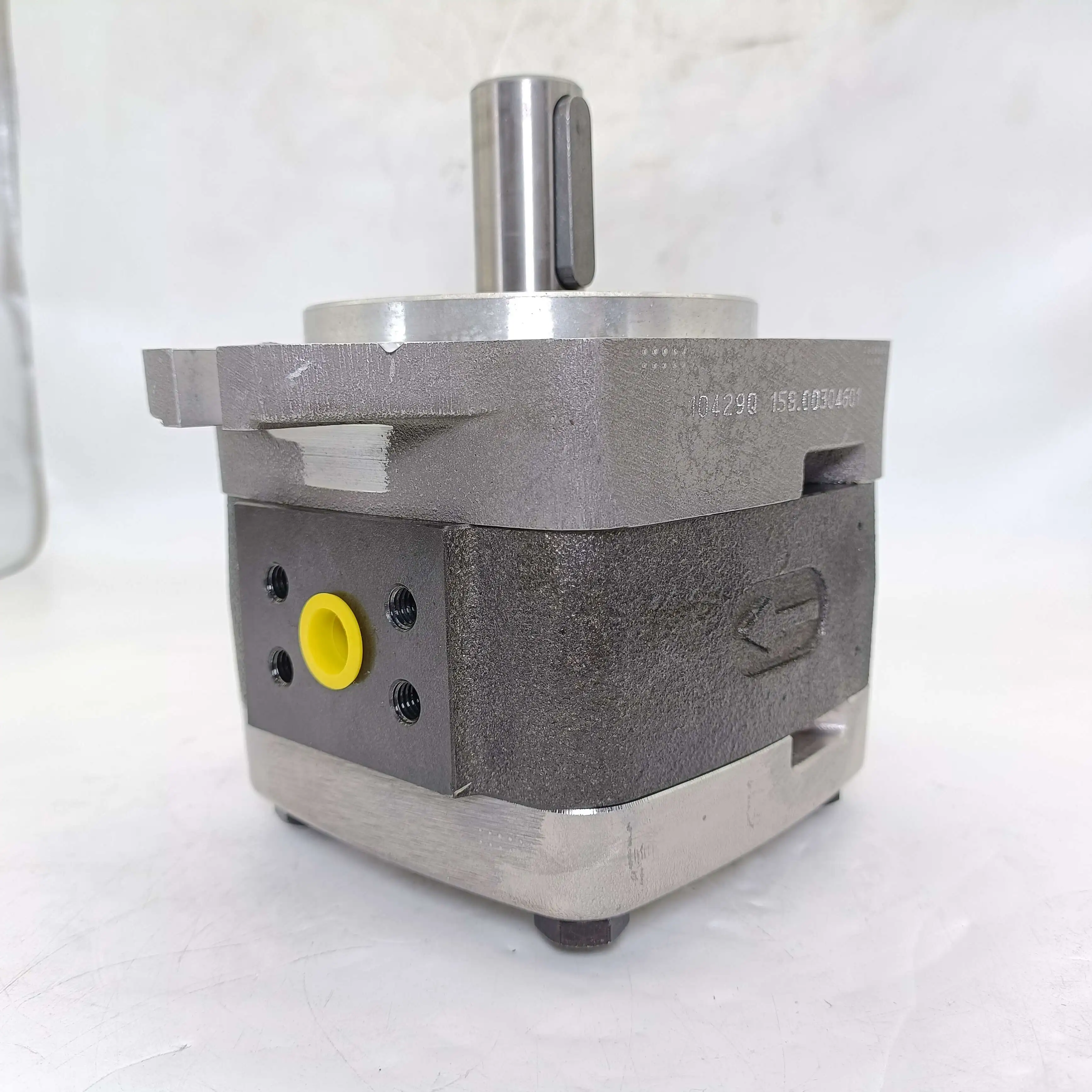
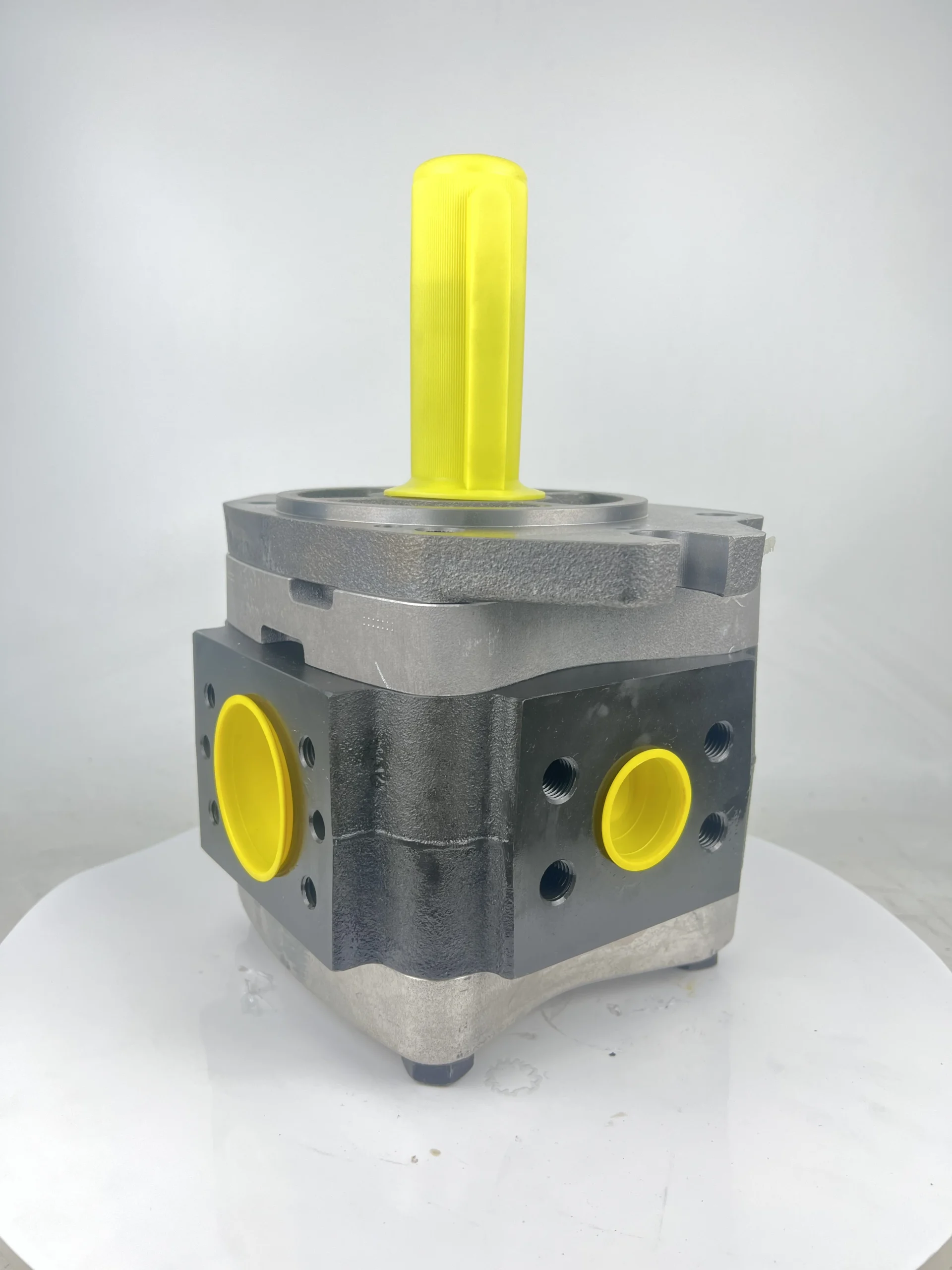
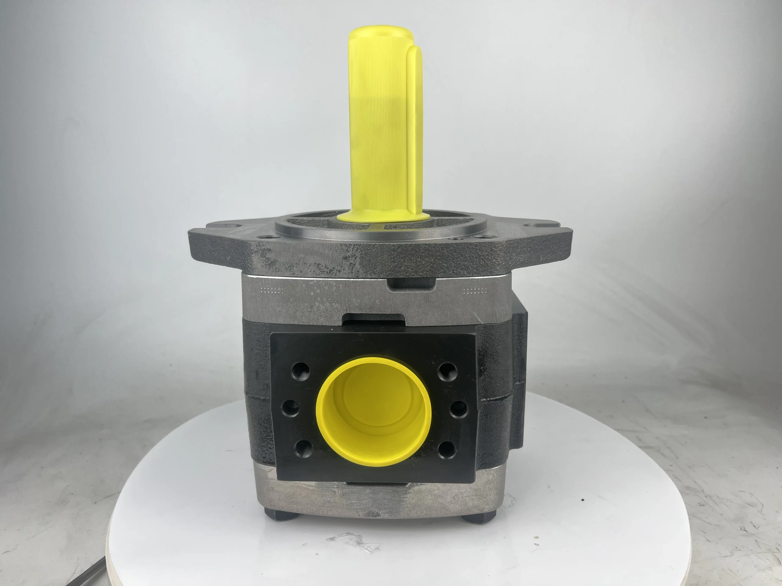
This gear pump is of internal meshing quantitative type and adopts an axial suction and discharge structure. The rated displacement is 80 cubic centimeters per revolution, with a volumetric efficiency of no less than 93% and a total efficiency of no less than 85%. The continuous working pressure can reach 280 bar, and the short-term peak pressure is 315 bar (with a cumulative duration not exceeding 100 hours). The rated speed is 1500 revolutions per minute, the maximum speed is 2400 revolutions per minute, and the minimum stable speed is 400 revolutions per minute. Within this speed range, the flow stability error is ≤1.5%. Under rated working conditions, the maximum output flow is approximately 121 liters per minute, corresponding to a continuous output power of about 45 kilowatts.Structurally, it adopts a cast iron housing, with a 6-tooth driving internal gear and a 7-tooth driven external gear inside. The high and low pressure chambers are separated by a crescent-shaped plate. The output shaft has a diameter of 38 millimeters and can withstand a radial force of no more than 1000 Newtons and an axial force of no more than 600 Newtons. It is installed with a square flange. The oil inlet has a G2 internal thread and the oil outlet has a G1½ internal thread. The overall weight is approximately 38 kilograms, and it is compact in size for easy installation.
This gear pump is of internal meshing quantitative type and adopts an axial suction and discharge structure. The rated displacement is 80 cubic centimeters per revolution, with a volumetric efficiency of no less than 93% and a total efficiency of no less than 85%. The continuous working pressure can reach 280 bar, and the short-term peak pressure is 315 bar (with a cumulative duration not exceeding 100 hours). The rated speed is 1500 revolutions per minute, the maximum speed is 2400 revolutions per minute, and the minimum stable speed is 400 revolutions per minute. Within this speed range, the flow stability error is ≤1.5%. Under rated working conditions, the maximum output flow is approximately 121 liters per minute, corresponding to a continuous output power of about 45 kilowatts.Structurally, it adopts a cast iron housing, with a 6-tooth driving internal gear and a 7-tooth driven external gear inside. The high and low pressure chambers are separated by a crescent-shaped plate. The output shaft has a diameter of 38 millimeters and can withstand a radial force of no more than 1000 Newtons and an axial force of no more than 600 Newtons. It is installed with a square flange. The oil inlet has a G2 internal thread and the oil outlet has a G1½ internal thread. The overall weight is approximately 38 kilograms, and it is compact in size for easy installation.
Compatible with L-HM 46/68 anti-wear hydraulic oil, the working temperature range is -20℃ to 80℃, and it can withstand 90℃ for a short time. The contamination degree of the oil should reach ISO 4406 17/14 grade, with a protection level of IP65, and it can adapt to industrial environments with a humidity of ≤95%.
Ii. Working Principle
It adopts the internal meshing positive displacement working principle, and the core is to achieve the conversion of hydraulic energy through the volume change generated by gear meshing. Inside the pump body, the driving internal gear and the driven external gear are eccentrically arranged. The crescent-shaped plate divides the space between the two gears into independent oil suction chambers and oil pressure chambers. When the prime mover drives the internal gear to rotate, the external gear rotates in the same direction. The teeth in the oil suction area gradually disengage from meshing, the volume of the sealed cavity increases to form a negative pressure, and the oil is sucked in and fills the gap between the teeth. As the gears continue to rotate, the space between the teeth carrying the oil moves to the oil pressure area. The teeth remesh, reducing the volume of the sealed cavity. The oil is then squeezed and discharged from the oil outlet, completing the conversion from mechanical energy to hydraulic energy.
The size of the flow rate is directly related to the rotational speed and displacement. The output flow rate per revolution is fixed, and the flow rate can be precisely controlled by adjusting the rotational speed. The output pressure is determined by the system load. The strength of the pump body and the sealing performance limit the maximum working pressure. The 7-tooth structure design keeps the flow pulsation rate at a relatively low level, effectively reducing system vibration and noise.
Iii. Product Features and Advantages
It has significant performance advantages. With a precise tooth profile design and a balanced thrust plate structure, its volumetric efficiency is as high as over 93%, saving 5-8% energy compared to ordinary gear pumps. The 7-tooth meshing combined with the optimized crescent plate design results in small flow pulsation and low operating noise. The noise value measured at 1 meter is ≤85 decibels. It has strong adaptability to the viscosity of oil and can convey media with a viscosity range of 10 to 300 square millimeters per second. Moreover, it has good self-priming ability and can achieve oil suction without an auxiliary pump.
The cast iron shell has high strength and strong impact resistance in structure. It is designed with roller bearings, and the average mean time between failures is ≥ 18,000 hours, making it suitable for harsh working conditions. The modular design enables key components such as gear pairs and distribution plates to be disassembled and replaced separately, making maintenance convenient and cost-effective. Compared with types such as plunger pumps, it is less sensitive to oil contamination and has a longer maintenance cycle.
In terms of control, it supports both forward and reverse rotation, with consistent output performance in both directions, and can be adapted to bidirectional driving scenarios. The pressure remains stable when the load changes, with a fast response speed. It is particularly suitable for variable-speed drive applications and can achieve precise flow control according to the working conditions.
Iv. Usage Functions and Purposes
The core function is to provide a stable high-pressure oil source for the hydraulic system and convert the mechanical energy of the prime mover into hydraulic energy. Precise flow control can be achieved by adjusting the rotational speed to meet the power requirements of different working conditions. It has the ability to supply oil in both directions and can drive the forward and reverse movements of the actuator. In addition, its structural characteristics enable it to be used as a transfer pump for transporting viscous media such as hydraulic oil and lubricating oil.
It is widely applied in multiple fields: in the industrial sector, it serves as the main pump for injection molding machines and die-casting machines to provide clamping and injection power, and as the power source for presses and machine tools to ensure processing accuracy. In the field of construction machinery, it is compatible with equipment such as excavators and loaders, providing hydraulic power for working devices such as booms and buckets. It can also be used in the lifting systems of municipal equipment such as dump truck and dump trailer, as well as in the hydraulic circuits of ship deck machinery and metallurgical equipment.
V. Applicable Machines and Scenarios
In industrial scenarios, it is compatible with injection molding machines (working pressure 200-280 bar, flow rate 80-100 liters per minute), used in mold locking and injection systems. The low pulsation feature enhances injection accuracy and product quality. Compatible with die-casting machines (working pressure 220-280 bar), it provides stable clamping force and injection power, ensuring the continuity of large-scale production. In the hydraulic system of machine tools (working pressure 140-200 bar), it drives the movement of the worktable and tool feed, and operates with low noise to improve the operating environment.
In the context of construction machinery, it is compatible with excavators (with a working pressure of 180-280 bar and a flow rate of 90-120 liters per minute), simultaneously driving multiple actuating elements to act in coordination. Under heavy load, it outputs high pressure and large flow rate, and under light load, energy conservation is achieved by adjusting the rotational speed. Compatible with loaders (working pressure 160-240 bar), it provides power for the lifting and tilting of the bucket. The anti-pollution design is suitable for the harsh environment of construction sites. In municipal equipment, for the dump body lifting system, remote operation can be achieved through pneumatic control or cable control.
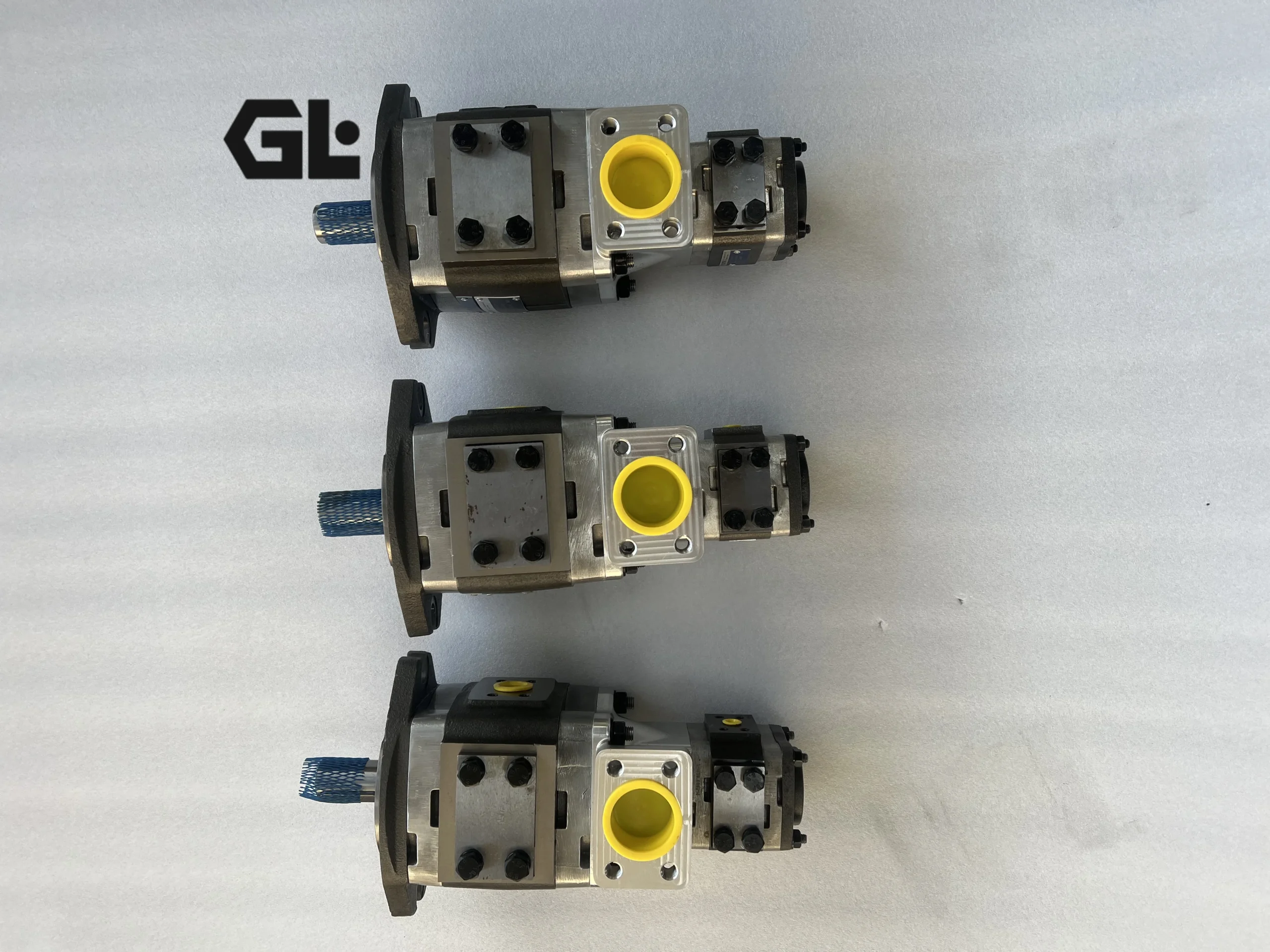
Six. Similar models
Among different specifications and models of the same series, the IPS 6-64 has a displacement of 64 cubic centimeters per revolution, a continuous working pressure of 300 bar, a flow rate of approximately 96 liters per minute, a power of 37 kilowatts, and a smaller volume (about 35 kilograms), making it suitable for medium-sized hydraulic systems. The IPS 6-100 has a displacement of 101.3 cubic centimeters per revolution, a continuous working pressure of 250 bar, a flow rate of approximately 152 liters per minute, and a power of 50 kilowatts. It is suitable for large-scale construction machinery and presses.
Among different series of the same type, the IPV 6-80 has the same displacement as the IPS 6-80. It is specially designed for constant-speed drive, with better stability, and is suitable for continuous and stable working conditions such as machine tools and fixed hydraulic power units. The IPVP 6-80 is a pressure-compensating variable type that can automatically adjust the displacement according to the system pressure, achieving an energy-saving effect of 20-30%. It is particularly suitable for scenarios with large load fluctuations such as excavators and injection molding machines. There are also fixed displacement models made of cast iron, integrating relief valves and pressure-holding valves, specially designed for municipal equipment lifting systems.
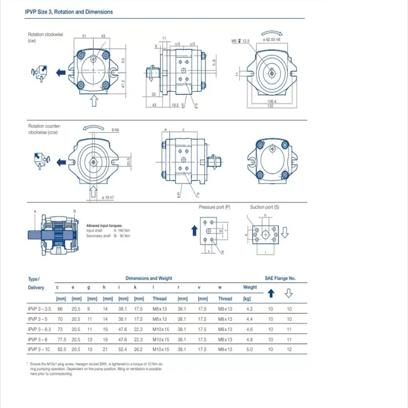
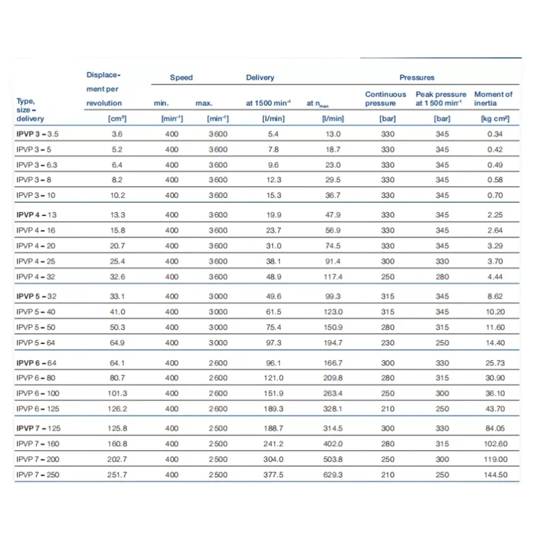
IPV3-3.5-101 、IPV3-5-101 、IPV3-6.3-101 、IPV3-8-101 、IPV3-10-101
IPV4-13-171 、IPV4-16-171 、IPV4-20-171 、IPV4-25-171 、IPV4-32-171
IPVP5-32-101 、IPVP5-40-101 、IPVP5-50-101 、IPVP5-64-101
IPVP6-64-101 、IPVP6-80-101 、IPVP6-100-101 、IPVP6-125-101
IPVP4-13-171 、IPVP4-16-171 、IPVP4-20-171 、IPVP4-25-171
IPV5-32-101 、IPV5-40-101 、IPV5-50-101 、IPV5-64-101、IPVP4-32-171
IPV6-64-101 、IPV6-80-101 、IPV6-100-101 、IPV6-125-101
IPV7-125-101 、IPV7-160-101 、IPV7-200-101 、IPV7-250-101
IPVP3-3.5-101 、IPVP3-5-101 、IPVP3-6.3-101 、IPVP3-8-101 、IPVP3-10-101
IPVP7-125-111 、IPVP7-160-111 、IPVP7-200-111 、IPVP7-250-111
Vii. Precautions for Use
When installing, it is necessary to ensure that the flatness of the installation plane is no more than 0.05 millimeters, and the coaxiality of the pump shaft and the drive shaft is no more than 0.08 millimeters. Elastic couplings must be used for connection, and rigid connections are strictly prohibited to avoid damaging the bearings. The suction pipe should be a short straight pipe with an inner diameter of no less than 50 millimeters and a length not exceeding 1.2 meters. A 100-mesh coarse filter should be installed. The distance between the suction port and the bottom of the oil tank should be no less than 250 millimeters to prevent excessive suction resistance and cavitation. The oil drain pipe must be connected to the oil tank separately, with a back pressure of no more than 0.05 megapascals, and must not be shared with other return oil pipes. The rotation direction must be strictly determined in accordance with the arrow marks on the pump body. Reverse rotation can lead to incorrect flow distribution and component damage.
Before starting, check the oil level in the oil tank, fill the pump with clean hydraulic oil, and manually rotate the pump 2 to 3 times to ensure there is no jamming. After confirming the correct rotation direction through jog start-up, run it no-load for 5 to 10 minutes until the oil temperature rises above 30℃. Then gradually load it, with each pressure increase not exceeding 50 bar and an interval of no less than 2 minutes. Sudden loading to the rated pressure is strictly prohibited. During operation, the oil temperature (normally 40-60℃, with a maximum not exceeding 70℃) and pressure (not exceeding 280 bar) need to be monitored. If abnormal noise, vibration or increased leakage (exceeding 1.5 milliliters per hour) occurs, the machine should be stopped immediately for inspection.
In terms of maintenance, check the oil level, oil temperature, oil pressure and leakage every 50 hours. Check the filter every 200 hours and clean or replace it if necessary. Change the hydraulic oil and thoroughly clean the oil tank every 1,000 hours to ensure that the oil contamination level meets the standards. Disassemble and inspect the wear of components such as gears and crescent plates every 2,000 hours. Compatibility tests should be conducted before mixing hydraulic oils of different brands. In cold regions, the oil should be preheated to above 10℃ before starting.
It is strictly prohibited to start or operate without oil. Even short-term dry running (more than 5 seconds) will cause severe wear on gears and distribution plates. To prevent cavitation caused by poor sealing of the oil suction pipeline or clogging of the filter, the suction pressure must not be lower than -0.02 megapascals. It is prohibited to operate simultaneously at the maximum pressure and the highest rotational speed for a long time. The cumulative duration of short-term peak pressure shall not exceed 100 hours. Before shutting down, the load should be unloaded to low pressure and run for 3 to 5 minutes. Only when the oil temperature drops below 60℃ should the power be cut off.
For short-term storage (≤30 days), the surface of the pump body should be cleaned, all oil ports should be sealed to prevent foreign objects from entering, and it should be stored in a dry and well-ventilated place. The pump should be turned by hand 1-2 times a month. For long-term storage (>30 days), anti-rust oil should be injected, and anti-rust grease should be applied to the output shaft. The anti-rust condition should be checked every quarter. Before reusing, the sealing parts should be replaced and a 2-hour no-load test run should be conducted.