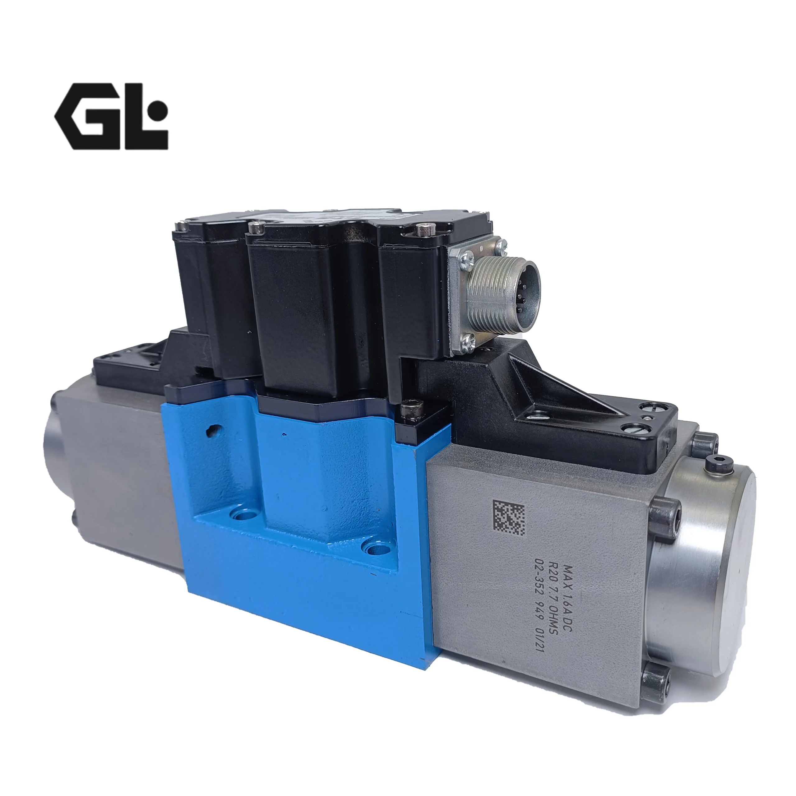
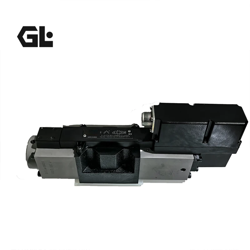
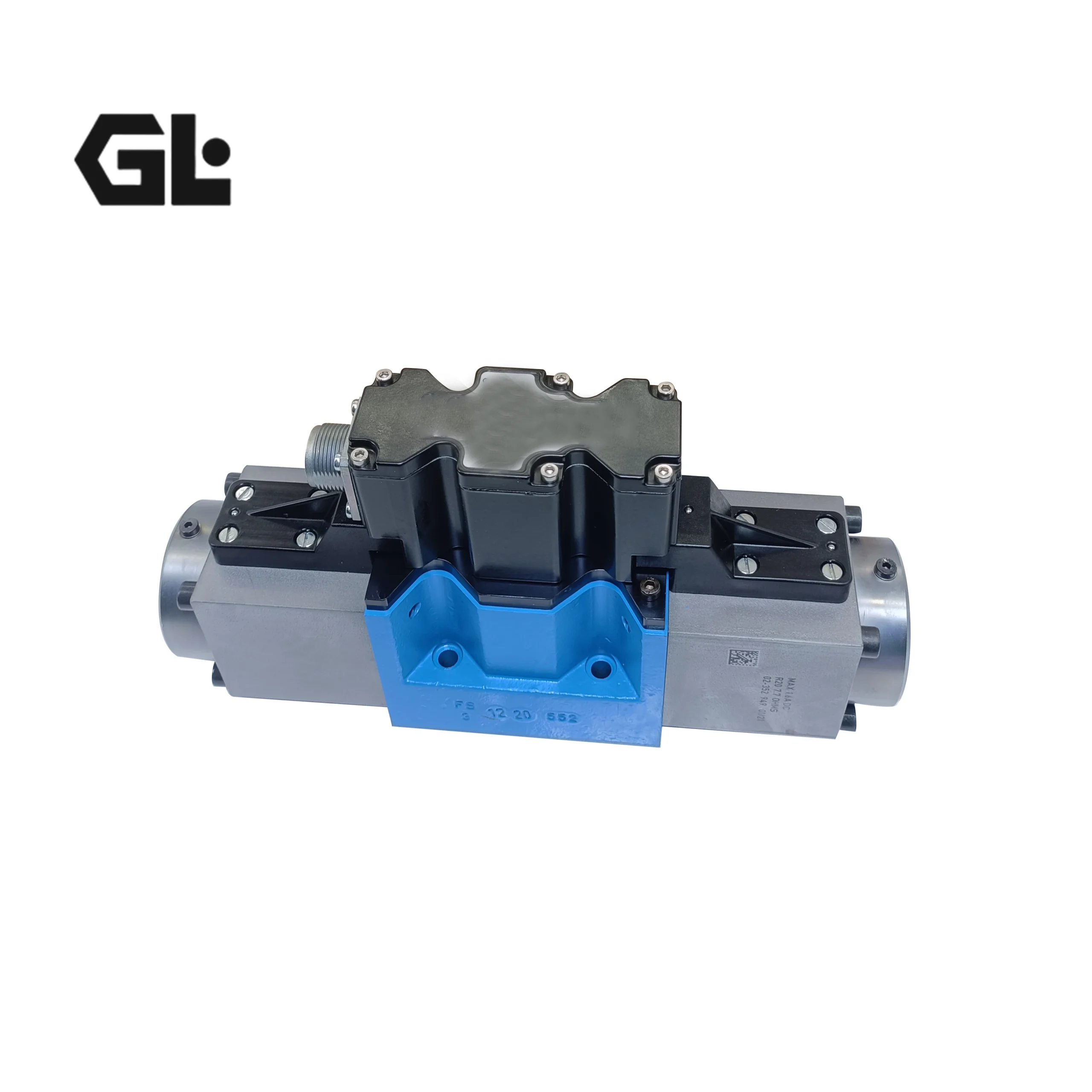

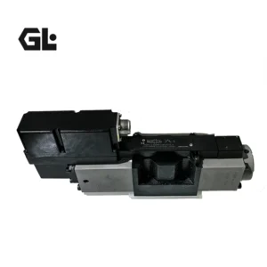
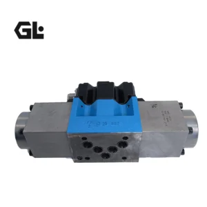

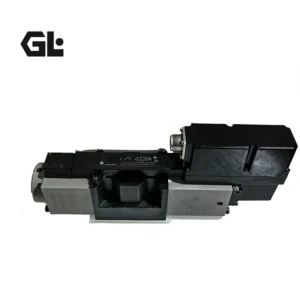

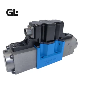
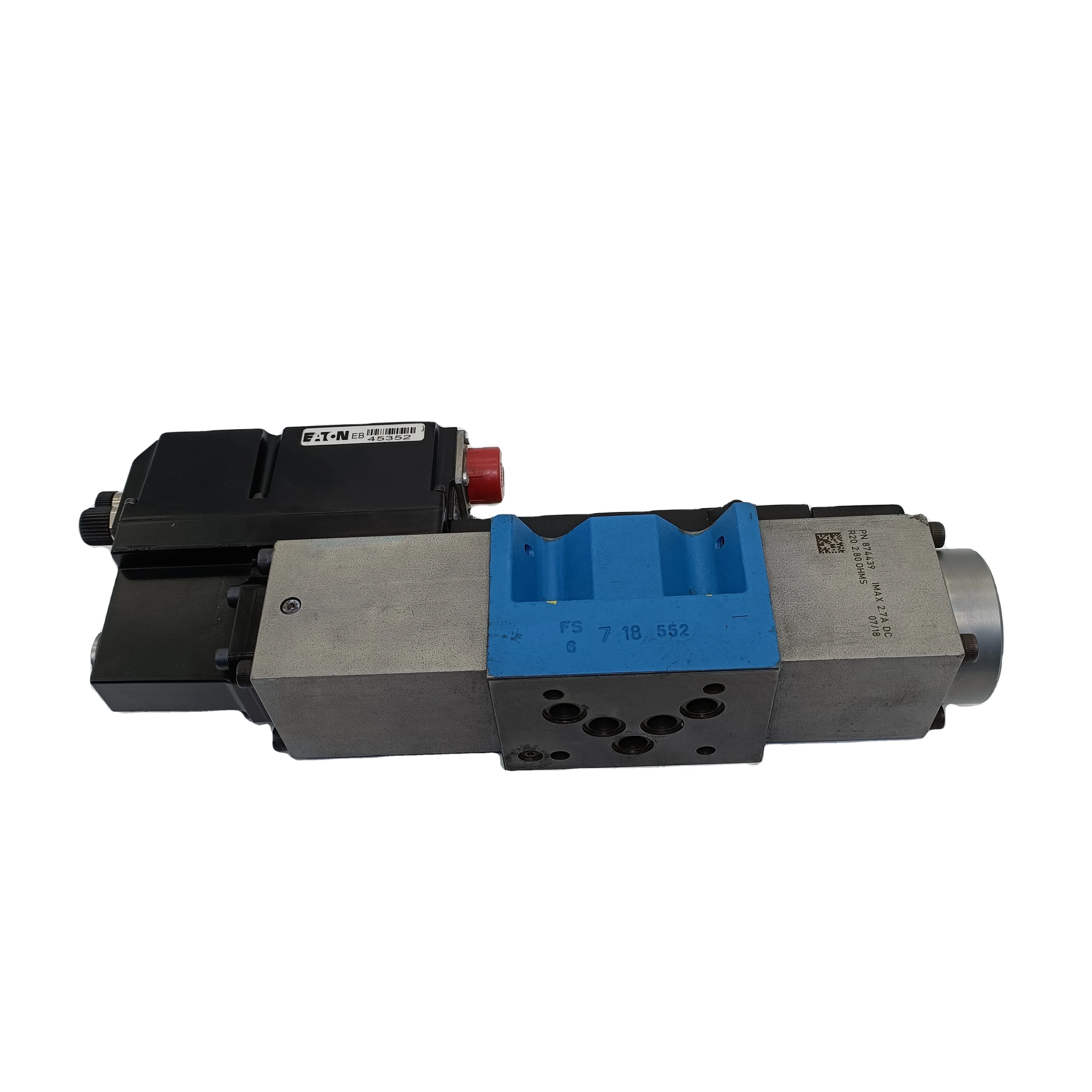
KBFDG4V Hydraulic Proportional Directional Valve KBFDG4V-5-2C50N25-Z-M1-PC7-H7-12 KBFDG4V-5-2C50N25-Z-PC7-H7-10 Hydraulic Valve
I. Model Analysis: KBFDG4V-5-2C50N25-Z-M1-PC7-H7-12
The model coding rules for the KBFD series proportional valves are clear. The meanings of each part are as follows (based on common standards, there may be minor differences from the latest version of the manual. It is recommended to refer to the official manual) :KBFD: Series of codes. Represents a pilot-operated electromagnetic proportional directional control valve with position feedback.
The model coding rules for the KBFD series proportional valves are clear. The meanings of each part are as follows (based on common standards, there may be minor differences from the latest version of the manual. It is recommended to refer to the official manual) :KBFD: Series of codes. Represents a pilot-operated electromagnetic proportional directional control valve with position feedback.
G: Valve core type/function. G represents the covering form and flow characteristics of the valve core. “G” usually stands for zero-cover/linear valve core, which has good linear control characteristics.
4V: Installation interface. 4V represents a four-port, base plate installation form that complies with the ISO 4401 standard.
5: Specifications/Dimensions. The interface size of the representative valve is CETOP 5 (approximately NG10, and the oil port thread is M18×1.5 or SAE-12).
2C: Coil type. 2C usually represents a double electromagnet proportional coil, which can be controlled proportionally in both directions.
50: Rated flow. At the rated pressure difference (usually 10 bar), the rated flow rate of the valve is approximately 50 L/min.
N: Valve core position feedback form. N stands for the built-in analog LVDT (Linear Variable Differential Transformer) displacement sensor, which is used for precise detection and closed-loop control of the valve core position.
25: Maximum working pressure. The maximum working pressure is 250 bar (25 × 10).
Z: Spring alignment form. Z represents double spring alignment. When there is no signal from either coil, the valve core automatically returns to the neutral position under the action of the spring.
M1: Center function of the valve core. It usually represents A specific transitional function, between O-type and H-type, and may be a variant of “Y-type” or “semi-O-type”. The specific connection relationship with ports A/B/T/P needs to be determined based on the sample.
PC7: Electrical connector form. PC7 is a standard multi-pin waterproof connector model (such as in compliance with DIN 43650 standard).
H7: Controller/Amplifier matching code. H7 refers to a specific amplifier model that is recommended or pre-calibrated and matched (such as one from Eaton’s EHP or EPL series).
12: Special options or version numbers. It may represent specific sealing materials, coatings, factory calibration codes or production batch identifiers.
A brief summary: This is a pilot-operated proportional directional valve of CETOP5 specification, with a rated flow rate of 50L/min, featuring LVDT position feedback, dual-spring centering, M1 median function, and compatible with a specific amplifier.
Ii. Product Attributes and Features
High performance: It adopts a pilot control structure, with a large driving force for the main valve core, fast response, and the ability to handle large flow rates.
High precision and controllability
LVDT position feedback: It realizes closed-loop control of valve core displacement, has strong anti-pollution ability, small hysteresis, high repeatability accuracy, and is not affected by oil temperature changes.
Zero-cover valve core (G type) : It offers excellent resolution and linearity, enabling precise speed and position control of the actuator.
Durable and sturdy: Suitable for harsh industrial and mobile device environments.
Flexibility
A variety of valve core functions (such as M1, etc.) are available to meet the median requirements of different systems.
It can be matched with various amplifiers (specified by H7 code) for parameter setting and fault diagnosis.
Modularization: Base plate installation, facilitating integration into the hydraulic system.
Iii. Working Principle
This valve is a two-stage pilot-operated proportional directional valve
Electrical signal input: An external controller (such as a PLC) sends an analog signal (typically ±10V or 4-20mA) to the valve’s dedicated amplifier (H7).
Pilot stage operation: The amplifier drives the corresponding proportional electromagnet (2C) to generate a thrust proportional to the electrical signal.
Pilot valve core drive: This thrust drives the small valve core of the pilot stage to move, thereby generating a pilot control pressure proportional to the input electrical signal.
Main valve core drive: The pilot pressure acts on the control piston at the end of the main valve core, overcoming the spring force to push the main valve core to move. The distance moved (the size of the opening) is proportional to the pilot pressure.
Position feedback and closed loop: The built-in LVDT sensor detects the actual displacement of the main valve core in real time and converts it into an electrical signal to be fed back to the amplifier. The amplifier compares the command signal with the feedback signal and continuously adjusts the current output to the electromagnet until the valve core precisely reaches the position required by the command, forming a position closed loop.
Flow control: The displacement of the main valve core determines the flow area from P to A/B and from A/B to T, thereby achieving continuous and proportional control of the speed and direction of the actuator (cylinder or motor).
Iv. Precautions for Installation and Operation
Oil cleanliness: Of vital importance! It is recommended that the cleanliness of the system oil reach ISO 4406 18/15/12 or better. A high-pressure filter (β₃≥75, recommended 10μm) must be installed before the oil inlet (P port) of the valve.
Base plate installation
The installation base plate must be flat and clean, and its flatness and surface roughness must meet the requirements.
The fastening bolts should be evenly tightened in a diagonal sequence to the specified torque to prevent the valve body from deforming and causing the valve core to get stuck.
Oil drain port (Y port) : The external oil drain port of the pilot valve must be directly and without back pressure connected back to the oil tank. Any back pressure will affect the performance of the valve and even cause malfunctions.
Electrical connection
Make sure to use the correct matching amplifier (H7 code) and connect the power supply, command signal and feedback signal correctly according to the wiring diagram.
The connector (PC7) should be locked tightly and protected from water and dust.
The amplifier must be properly grounded. The signal lines should use shielded cables and be arranged separately from the power lines to prevent interference.
First startup
Before starting, check the oil level and jog the motor to exhaust.
When powering on for the first time, it is recommended to perform it under zero input signal to allow the system to self-check or align the valve core.
Parameter Settings: Through the matched amplifier, it is usually necessary to set parameters such as dead zone compensation, gain, and ramp time to optimize the dynamic performance of the system.
Maintenance: Do not disassemble the valve core at will. Maintenance must be carried out in a super-clean environment.
V. Application Model (Without brand)
This series of valves are widely used in equipment that requires precise motion control due to their high performance and reliability
Construction machinery
Excavator: It is used for precise proportional control of the boom, bucket arm and bucket to achieve fine and flat operations.
Crane: It is used for smooth and anti-sway speed control of hoisting, luffing and telescopic boom.
Concrete pump truck: Used for precise position and speed control of the material rod.
Paver: Automatic leveling control for screed plates.
Industrial equipment
Injection molding machine: Used for speed and pressure control during injection and mold moving.
Metal press/bending machine: It is used for the synchronous control of the downward speed and position of the slider.
Testing machine: Servo control for load and displacement.
Robots and automated equipment: As the core control component of the hydraulic drive unit.
Vi. Complete Model List of KBFDG Series
1. Classified by path (NG3, NG6, NG10, NG16)
NG3 Series (diameter approximately 6mm) :
KBFDG4V-3-2C13N-Z-M1-PE7-H7-12
KBFDG4V-3-33C07N-Z-M1-PE7-H7-12
NG6 Series (diameter approximately 10mm) :
KBFDG4V-5-2C50N25-Z-M1-PC7-H7-12 (This model)
KBFDG4V-5-2C50N-Z-M1-PE7-H7-11
KBFDG4V-5-33C50N-Z-M1-PC7-H7-11
KBFDG4V-5-2C70N-Z-M1-PE7-H7-10
KBFDG4V-5-33C30N-Z-M2-PE7-H7-10
NG10 Series (diameter approximately 16mm) :
KBFDG4V-7-2C100N-Z-M1-PE7-H7-12
2. Classification by valve core type
2C type (Closed median)
KBFDG4V-5-2C50N25-Z-M1-PC7-H7-12
KBFDG4V-5-2C70N-Z-M2-PE7-H7-12
Type 33C (P port closed, A/B fuel tanks connected) :
KBFDG4V-5-33C50N25-Z-M1-PC7-H7-11
KBFDG4V-3-33C20N10-Z-V-PE7-H7-10
3. Classification by control type
With position feedback
KBFDG4V-5-2C50N25-Z-M1-PC7-H7-12 (PC7 = with LVDT feedback)
Without position feedback
KBFDG4V-5-2C50N-Z-M1-PE7-H7-11 (PE7 = Basic Type)
4. Special models
KBFDG5V-7-2C150N85-X-M1-PE7-H1-10 (High Flow Type)
KBFDG4V-3-2C28S-Z-M1-PC7-H6-11 (Special Sealing Type)
Vii. Differences between the KBFDG Series and Other Series
Compared with the common electromagnetic directional control valve (DG4V series) :
Control accuracy: KBFDG can continuously and proportionally control flow and direction, while DG4V can only be switched on and off
Response characteristics: KBFDG switches smoothly without shock, while DG4V switches with pressure fluctuations at the moment
Control mode: KBFDG can be remotely controlled simply by electrical signals, while DG4V requires a relay or PLC
Application scenarios: KBFDG is suitable for occasions requiring precise control, while DG4V is suitable for simple switch control
Compared with servo valves:
Cost-effectiveness: KBFDG is cheaper and easier to maintain, making it an economical alternative to servo valves
Precision range: Servo valves have higher precision (suitable for nano-scale control), and KBFDG meets industrial-grade precision control requirements
Anti-pollution capacity: KBFDG is superior to servo valves and has slightly lower requirements for oil cleanliness