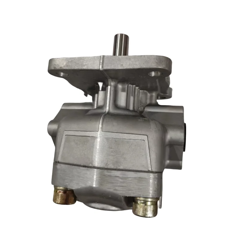


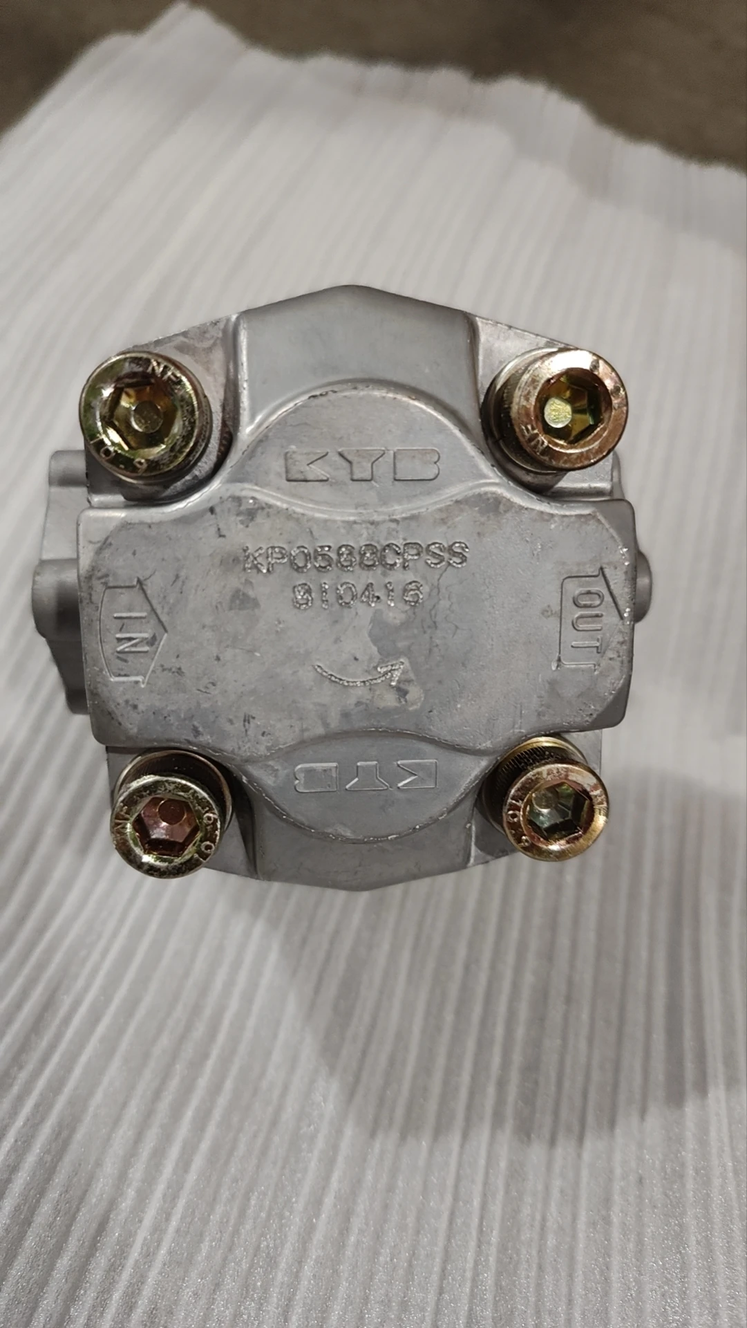
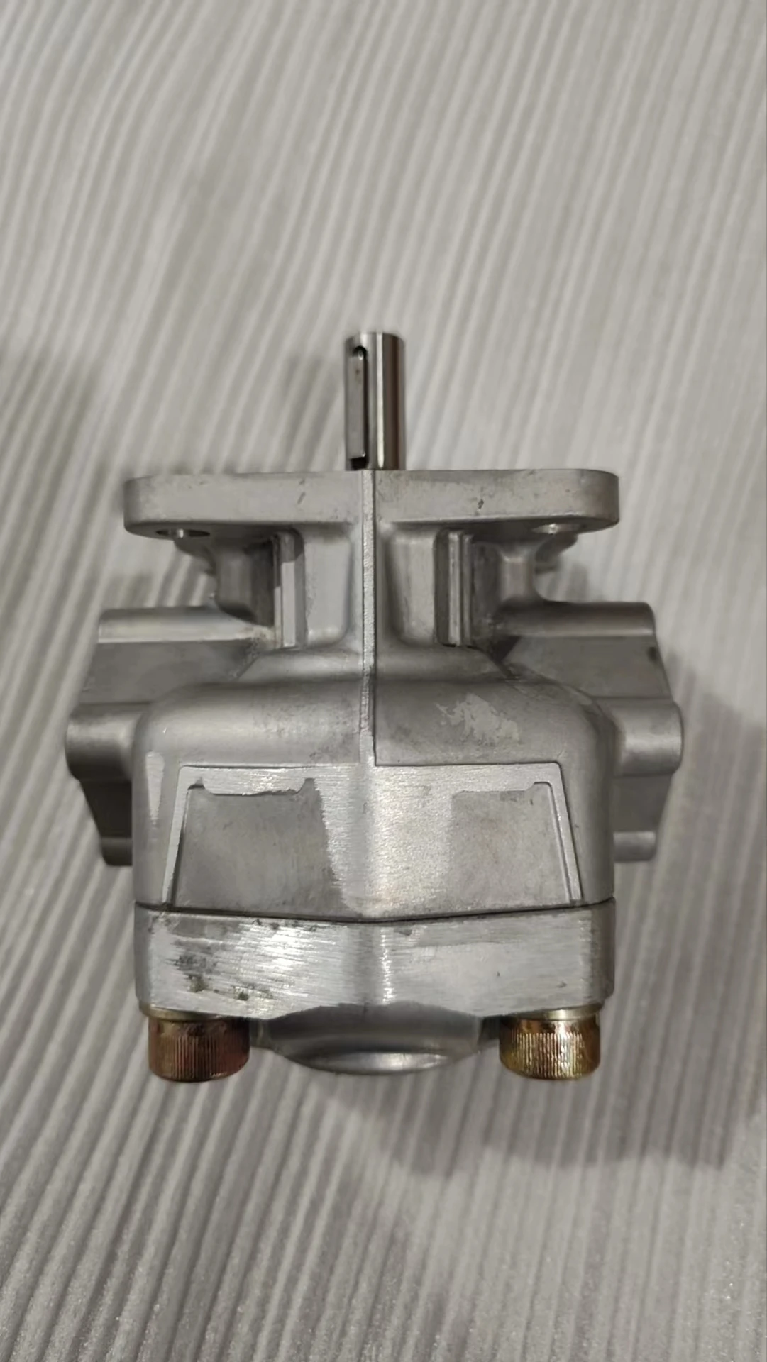
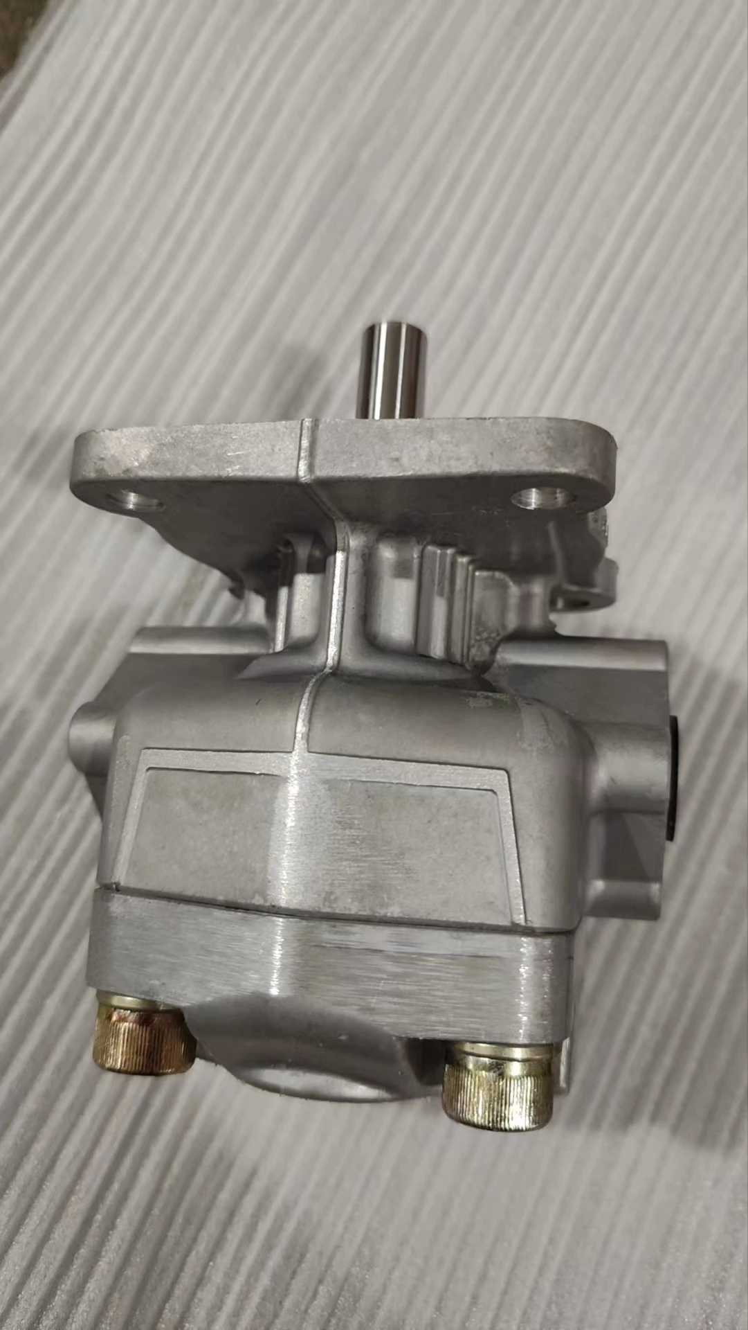


KP0588CPSS KYB KP05 Hydraulic Single Gear Oil Pump KP0530 KP0535 KP0540 KP0553 KP0560 KP0570 KP0588 High Pressure
| Model Number | KP0588CPSS |
|---|
SKU
N/A
Categories Gear Pump, Hydraulic Pump
Tags 12 volt oil pump, cooking oil pump, crude oil pump, electric oil pump, gear oil pump, hand oil pump, high pressure water pump, high volume water pump, hot oil pump, lube oil pump, manual oil pump, oil pump, pressure washer pump, waste oil pump, water pressure booster pump
Product Description
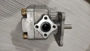
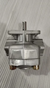
KP0588CPSS KYB KP05 Hydraulic Single Gear Pump KP0530 KP0535 KP0540 KP0553 KP0560 KP0570 KP0588 High Pressure Oil Pump
I. Core Technical Parameters
Basic specifications
Type: High-pressure external gear pump, belonging to the KP05 series, with a displacement of approximately 40ml/r (the “40” in the model corresponds to it)
Working pressure: Continuous operation 280bar (28MPa), short-term peak 300bar (30MPa) (cumulative not exceeding 10% of the total operating time)
Rated speed: 2000-2500r/min, maximum speed 3000r/min, minimum stable speed ≥300r/min
Theoretical flow rate: approximately 80-100L/min (at 100% efficiency, displacement × rated speed ÷1000)
Volumetric efficiency: ≥92%, total efficiency ≥85%, pressure pulsation ≤5%
Power requirement: approximately 38kW (under conditions of 280bar and 2500r/min), and the recommended motor power is ≥45kW
Torque: The theoretical output torque is approximately 179Nm (calculation formula: Displacement × pressure ÷(2π))
Structure and Connection
Housing: High-strength cast iron, with a pair of high-precision hard-toothed surface gears (module 2.5-3, number of teeth approximately 17) inside
Shaft end: Spline connection (DIN 5480 standard), diameter 42mm, can withstand radial force ≤5000N
Installation method: Flange type (ISO 3019 standard), internal thread G2 for oil inlet and return ports, internal thread G1 for oil drain port
Weight: Approximately 25kg (excluding accessories), dimensions: approximately 350×280×240mm
Hydraulic system adaptation
Applicable oil: L-HM 46/68 anti-wear hydraulic oil, viscosity range 15-400mm²/s, recommended 20-50mm²/s
Operating temperature: -20℃ to 80℃. It is recommended to control it within 40-65℃ for continuous operation
Oil cleanliness: ISO 4406 18/15 grade. A 200-mesh oil filter is required for return oil and a 100-mesh oil filter for inlet oil
Protection grade: IP65, suitable for dust and liquid jet environmentsIi. Working Principle
The basic working mechanism of an external gear pump:
Core structure: The pump is composed of a driving gear, a driven gear and a pump body. The two gears mesh with each other in a closely fitting housing to form a sealed working chamber
Oil absorption process
The driving gear is driven to rotate by the prime mover (motor or engine), which in turn drives the driven gear to rotate in the opposite direction
When two gears disengage from the meshing area, the volume between the teeth gradually increases, creating a local vacuum
Under the action of atmospheric pressure, the oil in the oil tank enters the pump chamber through the oil suction port and fills the gap between the teeth
Oil pressing process
The gears continue to rotate, and the oil is carried to the oil drainage area by the space between the teeth
In the oil discharge area, the gears enter the meshing state, the volume between the teeth decreases, and the oil is squeezed to form high pressure
High-pressure oil is output to the hydraulic system through the oil outlet, completing one working cycle
Sealing and unloading
The precise fit between the pump body and the gears (with a clearance of 0.03-0.05mm) forms multiple seals, reducing leakage
It adopts a special unloading groove design to balance axial and radial pressures, reduce bearing load and extend service life
Work characteristics
The flow rate is directly proportional to the rotational speed, and the pressure is directly proportional to the load. The flow rate can be steplessly controlled by adjusting the rotational speed
It features a simple structure, reliable operation, low sensitivity to oil contamination and low maintenance cost
The output flow is continuous and stable without pulsation (compared with plunger pumps), making it suitable for systems that require smooth movement
It can work in both forward and reverse directions. Just switch the connection of the oil inlet and outlet ports to adapt to bidirectional hydraulic systems
Iii. Product Features and Advantages
1. Advantages in high-pressure performance
High working pressure: 280bar continuous working pressure, 300bar peak pressure, meeting the requirements of high-pressure systems, with high output power density
Stable high-pressure output: Special bearing design and housing structure can withstand high radial and axial forces, ensuring long-term stable operation under high-pressure conditions
Low noise: Optimized gear parameters and structural design keep noise below 80dB, improving the working environment
2. Structural and efficiency advantages
Compact and lightweight: With the same power, it is 30% smaller in volume and 20% lighter in weight than a plunger pump, making it convenient for installation and use in space-constrained environments
High efficiency: Volumetric efficiency ≥92%, total efficiency ≥85%, low energy loss, and energy conservation
Long service life: The gears are made of high-quality alloy steel and undergo surface quenching treatment (hardness HRC58-62), with an average mean time between failures of ≥ 12,000 hours
Strong self-priming ability: No additional oil drawing device is required. It starts up quickly and the oil drawing height can reach 500mm (recommended ≤300mm).
3. Reliability and adaptability
Strong anti-pollution ability: The requirement for oil cleanliness is lower than that of plunger pumps (ISO 18/15 vs 17/14), reducing the frequency of filter replacement
Wide adaptability
Wide temperature adaptability range: -20℃ to 80℃, suitable for different environmental working conditions
The viscosity adaptability range is wide: 15-400mm²/s, and hydraulic oils of different viscosity grades can be used
The speed adaptation range is wide: 300-3000r/min, and it can be matched with various prime movers
Easy maintenance: Simple structure, easy to disassemble and assemble, low maintenance cost, and can be maintained and serviced by general maintenance personnel
Iv. Usage Functions and Purposes
Core functions
Convert the mechanical energy of the prime mover (motor, engine) into hydraulic energy to provide high-pressure oil for the hydraulic system
Precisely control the output flow and pressure to meet the working requirements of different actuating elements (hydraulic cylinders, hydraulic motors)
As the power source of the hydraulic system, it realizes various actions of mechanical equipment (linear motion, rotational motion, clamping, etc.)
Main application fields
Construction machinery
The hydraulic systems of the working devices (boom, bucket arm, and bucket) of excavators and loaders provide high-pressure power
The vibration system of the roller provides stable vibration energy
The forklift lifting and tilting system ensures smooth transportation of goods
Industrial hydraulic system
The injection molding machine clamping and injection system provides high-pressure clamping force and precise injection control
Hydraulic press (100-500 ton class), providing high-pressure liquid to achieve material pressing and forming
Metal processing equipment (pipe benders, shearing machines), providing stable working pressure
Agricultural machinery
The hydraulic suspension system of the tractor controls the lifting of agricultural tools and the depth of operation
The header and conveying system of the harvester ensure smooth and efficient harvesting and conveying
Combine harvester threshing and separation device, providing stable hydraulic power
Other applications
Ship deck machinery (such as anchor winches and winches), suitable for harsh Marine environments
Mining machinery (such as underground drilling RIGS) provides high-torque hydraulic power
Hydraulic tools (hydraulic wrenches, hydraulic jacks), providing portable high-pressure sources
V. Applicable Machines and Scenarios
1. Typical applicable machines
10-20 ton excavators: Working pressure 180-280bar, flow rate 60-100L/min, control excavation actions, response time < 10ms, ensuring precise and efficient operation
For 200-500 ton injection molding machines: The clamping pressure should be 200-280bar and the flow rate 30-80L/min, providing stable high pressure to ensure tight mold closure and prevent melt leakage
Medium-sized hydraulic press: Working pressure 250-280bar, flow rate 50-100L/min. It is used in metal forming and pressing processes, requiring stable pressure and high repeatability accuracy
3-5 ton forklifts: The lifting system pressure is 160-200bar, and the flow rate is 40-60L/min, ensuring the rapid and smooth lifting of goods. The tilting system pressure is 120-160bar to prevent the goods from toppling over
Agricultural tractors (over 100 horsepower) : The hydraulic suspension system has a pressure of 140-180bar and a flow rate of 30-50L/min. It controls the lifting of agricultural machinery and the depth of tillage, adapting to different soil conditions
2. Characteristics of applicable scenarios
Systems requiring stable high-pressure output: pressure ≥160bar, flow ≥30L/min, such as hydraulic presses and large injection molding machines
Equipment with limited space but high power demands, such as small excavators and compact hydraulic workstations, require pumps to be small in size, light in weight and have high output power
Applications with high requirements for flow stability: such as precision processing equipment and textile machinery, flow fluctuation ≤±2%, ensuring processing accuracy
In harsh environmental conditions:
Dust environment (mines, construction sites) : Protection grade IP65, preventing dust from entering
Large temperature fluctuation (-20℃ to 80℃) : Suitable for use in different seasons and regions
Damp environments (ships, underwater equipment) : Excellent sealing performance to prevent moisture from entering
Systems that require frequent start-stop and load changes, such as construction machinery and injection molding machines, should respond quickly and adapt to changes in working conditions
Six. Similar models
1. Different displacement models of the same series
KP0530CPSS: Displacement approximately 30ml/r, continuous pressure 280bar, rated speed 2500-3000r/min, flow rate approximately 75L/min, power approximately 28kW, weight approximately 22kg. It is suitable for small hydraulic systems, small injection molding machines, and agricultural machinery
KP0553CPSS: Displacement approximately 53ml/r, continuous pressure 280bar, rated speed 2000r/min, flow rate approximately 106L/min, power approximately 45kW, weight approximately 28kg. It is suitable for large-scale construction machinery, heavy-duty hydraulic presses, and large injection molding machines
KP0523CPSS: Displacement approximately 23ml/r, continuous pressure 280bar, rated speed 3000r/min, flow rate approximately 69L/min, power approximately 23kW, weight approximately 20kg. It is suitable for small hydraulic tools and auxiliary hydraulic systems
2. High-pressure gear pumps of the same type but different series
KFP Series: Also a high-pressure gear pump, it features a cast iron housing, a compact and lightweight design, a displacement range of 16-125ml/r, and a maximum working pressure of 300bar. It is suitable for forklifts, small excavators, etc
KFS series: High-pressure gear pumps, featuring a special sealing design, can withstand higher back pressure (≤10MPa) and are suitable for systems that require strict leakage control
KRACHT KP series: German brand high-pressure gear pumps, displacement 1.4-300cm³/rev, maximum working pressure 400bar, temperature range -20 ℃ to 150℃, suitable for industrial systems with high precision and high reliability requirements
3. Hydraulic pumps of different types but with similar functions
Plunger pump series
A2F series axial piston pumps: They have a wide range of displacement, with pressure up to over 400bar, higher efficiency (≥95%), and are suitable for ultra-high pressure and high-precision systems. However, they are relatively expensive and have high requirements for oil cleanliness
YCY series axial piston pumps: They can achieve a pressure of up to 31.5MPa, have a wide flow range, and are suitable for construction machinery, metallurgical equipment, etc. However, they have a complex structure and high maintenance costs
Vane pump series
PV2R series vane pumps: They feature uniform flow, low noise, and compact size. The pressure is generally ≤210bar. They are suitable for systems with high requirements for noise and flow stability. However, they have poor anti-pollution ability and are not suitable for harsh environments
KP0530AHSS, KP0540AGSS, KP0540CGSS, KP0540AHSS, KP0540CHSS, KP0540CQSS, KP0553AGSS,
KP0553CGSS, KP0553AHSS, KP0553CHSS, KP0553CJSS, KP0553-53CSES, KP0553ASSS, KP0553CTS, KP0560AGSS,
KP0560CGSS, KP0560AHSS, KP0560ARSS, KP0560ASSS, KP0560CSSS, KP0570AGSS, KP0570CGSS, KP0570AHFS,
KP0570AHSS, KP0570CHSS, KP0570AJSS, KP0570CJSS, KP0570ANSS, KP0570ASSS, KP0570CSSS, KP0570ATSS,
Vii. Precautions for Use
1. Installation points
Fixed foundation
The flatness of the installation plane should be ≤0.1mm to ensure the stability of the pump body and reduce vibration and noise
The fixing bolts should be tightened evenly (with a torque of approximately 50-70N · m) to prevent the housing from deforming and affecting the gear meshing
Axis alignment
The coaxiality with the shaft of the drive equipment (motor, engine) should be ≤0.05mm. It is recommended to use an elastic coupling (rigid connection is prohibited).
After the coupling is installed, the pump shaft should be able to rotate easily without any jamming or imbalance
Oil port connection
The diameter of the inlet and return oil pipes is ≥32mm and the length is ≤3m to reduce pressure loss
The oil drain pipe must be connected to the oil tank separately and not in parallel with the return oil pipe. The back pressure should be ≤0.3MPa to prevent damage to the oil seal
All pipelines must be thoroughly cleaned to ensure there are no iron filings, welding slag or other impurities
Confirmation of rotation direction
Before starting, check that the motor’s rotation direction is consistent with the arrow marked on the pump. Connecting it in reverse will cause incorrect suction and discharge directions, fail to establish pressure, and may also damage the oil seal
2. Startup and Operation management
Startup program
Check the oil level in the fuel tank (more than 200mm above the suction port) to ensure that the suction pipe is submerged
Manually turn the wheel 2 to 3 times to ensure there is no jamming
Loosen the plug of the oil drain port, expel all the air inside the pump, and then tighten it
Start the system under no-load conditions (set the system relief valve to the minimum pressure) and run it for 5 to 10 minutes until the oil temperature rises above 30℃
Gradually increase the pressure (each increase ≤30% of the rated pressure, with an interval of ≥2 minutes). It is strictly prohibited to directly load the cold machine at full load
Key points of operation monitoring
Oil temperature: Normal 40-65℃, not exceeding 80℃ at the maximum. (If the temperature exceeds the limit, stop the machine to check whether the cooling system or the viscosity of the oil is appropriate.)
Pressure: Not exceeding the rated 280bar, peak value ≤300bar and cumulative time ≤10 minutes per hour
Noise: ≤80dB during smooth operation. Abnormal noise (>85dB) indicates possible wear, cavitation or loosening. The machine should be stopped immediately for inspection
Leakage: Normal allowable trace leakage (less than 5 drops per hour). If the leakage increases, the sealing parts should be inspected and repaired in time
3. Maintenance and care
Daily inspection
Check the oil level, temperature, noise and leakage conditions every shift, and record the operating parameters
Check if the connecting bolts are loose and tighten them in time
Regular maintenance
Every 250 hours: Check the filter and replace the filter element if necessary (the return oil filter must be replaced when the pressure difference is greater than 0.15MPa).
Every 800 hours: Conduct a comprehensive inspection of the seals and replace any aged or damaged sealing rings
Every 1500 hours: Check the contamination level of the oil. Replace the hydraulic oil if necessary (while cleaning the oil tank and pipelines).
Every 2500 hours: Disassemble and inspect the wear of gears and bearings, and measure the fit clearance (gear meshing clearance ≤0.15mm, bearing clearance ≤0.08mm)
Oil Product management
Hydraulic oils of different brands must not be mixed to prevent the reaction of additives and the formation of sediment
In cold regions (ambient temperature ≤-10℃), L-HV low-temperature hydraulic oil should be used to improve low-temperature fluidity
When changing the oil, the system should be thoroughly cleaned to prevent the mixture of new and old oil from affecting performance
Regularly (every 500 hours) check the viscosity and contamination of the oil to ensure they meet the requirements
4. Special Precautions
It is strictly prohibited to operate without oil: Even a short period of dry running (>5 seconds) will cause the gears and pump body to sinter, resulting in irreversible damage
Prevent cavitation
Make sure the oil suction pipe is well sealed to prevent air from entering the system
The oil suction height should be ≤500mm, and it is recommended to be ≤300mm to reduce the oil suction resistance
When the oil temperature is too low (<10℃), it should be run without load for 10 to 15 minutes first to raise the oil temperature before loading
The pressure drop of the oil suction port filter is less than 0.03MPa to prevent cavitation caused by excessive oil suction resistance
Load matching
It is not allowed to operate simultaneously at the maximum pressure and maximum speed for a long time (as this will cause overheating and excessive wear).
When designing the system, the pump should operate within the range of 70-85% of the rated pressure to increase its service life
Shutdown protection
Before shutting down, the load should be unloaded to low pressure (≤50bar) and run for 3 to 5 minutes. Only when the oil temperature drops below 60℃ should the power be cut off
Before long-term shutdown, it should be run without load for 10 minutes to completely relieve the system pressure and prevent the oil from oxidizing
For long-term storage, all oil ports should be sealed to prevent dust and it should be placed in a dry and well-ventilated area
Company Profile


Frequently Asked Questions
1.What ls our Main Products?
1.Hydraulic pump
2.Hydraulic valve
3.Hydraulic motor
4.Hydraulic cylinder
5.Hydraulic parts
2. What about the MOQ?
3.What are your advantages?
- Adhere to quality first.
- Support customization, ODM & OEM service.
- 1-year warranty and complete after-sales support.
- Safe and fast shipping worldwide.
- 24-hour online service for your inquiries.
4.Are you a manufacturer? What’s your delivery time?
Yes, we are a manufacturer with our own factory.
Common models are in stock, and orders are usually shipped within 1–3 days.
5.Which payment methods are accepted?
We accept T/T, L/C, PayPal, VISA, Western Union, Apple Pay, Google Pay, Afterpay (Clearpay), Klarna, and Trade Assurance.
For full orders: 30% deposit, balance before shipment.
For small/sample orders: full payment in advance.
6.How will you deliver my goods?
We offer flexible shipping options: DHL, UPS, FedEx, TNT, EMS, as well as air or sea freight.
All deliveries ensure door-to-door fast and safe service.
7.How do you inspect and guarantee your products?
All products are tested before shipment to ensure perfect working condition.
We offer a 12-month warranty — if a product fails due to quality issues, we provide free spare parts or repair support.
8.What about after-sales service?
If you encounter any problem during use, please contact your sales manager or our support team at any time.
We will respond quickly and help solve the issue efficiently.
9.What are your main applications?
- Hydraulic systems
- Agricultural machinery
- Construction machinery
- Automobile industry
- Local distributors and maintenance centers
10.Can I get a discount for bulk orders?
Yes. We offer competitive wholesale prices and try our best to give benefits to long-term partners.
Shoot Us An Email
Professional Manufacturer