


MMF044DAF1ABNNN Sauer Danfoss Series 40 Motor 44cc 380Bar
| Model Number | MMF044DAF1ABNNN |
|---|
SKU
N/A
Categories Hydraulic Motor, Piston Motor
Tags char-lynn motor, danfoss hydraulic motor, eaton hydraulic motor, gerotor motor, high speed hydraulic motor, hydraulic gear motor, hydraulic wheel motor, orbit hydraulic motor, parker hydraulic motor, parker motor, poclain hydraulic motor, rexroth hydraulic motor, sai hydraulic motor, staffa hydraulic motor, vickers hydraulic motor
Product Description
Product Overview
The Series 40 MMF fixed displacement axial piston motor represents a field-proven hydraulic drive solution within the Sauer Danfoss Series 40 platform, engineered specifically for closed-circuit hydrostatic transmission systems of medium power. The motor features a parallel axial piston/slipper design with a fixed swashplate, delivering a constant ratio between pump input flow and shaft output speed. Its robust, compact construction has made it a benchmark solution for mobile machinery hydrostatic drives worldwide.
The specific model covered in this document — MMF044DAF1ABNNN — is the M44 frame size configuration with 44 cm³/rev displacement, standard SAE flange mounting, and a 15-tooth 16/32 pitch spline output shaft. It is manufactured to original Sauer Danfoss specifications with 100% drop-in interchangeability, requiring no modification to mounting interfaces, port positions, or hydraulic connections. Every unit undergoes 100% simulated operating condition testing at the factory, including rated pressure loading, volumetric efficiency verification, case pressure validation, and seal integrity assessment prior to shipment.
The model code MMF044DAF1ABNNN follows the standard Sauer Danfoss coding convention: MMF designates the fixed displacement motor series; 044 indicates a theoretical displacement of 44 cm³/rev; D denotes the 35cc & 44cc product type; A specifies the standard shaft seal group; F identifies the 15-tooth 16/32 pitch spline output shaft; 1 indicates the end cap configuration; A specifies the mounting flange and port configuration; B denotes the rotation direction; and NNN indicates no special hardware features.
Technical Specifications
MMF044DAF1ABNNN:
Series / Type: Sauer Danfoss Series 40 MMF fixed displacement axial piston motor
Displacement: 44 cm³/rev (2.65 in³/rev)
Design: Parallel axial piston/slipper with fixed swashplate, swashplate design
Rated pressure: 34.5–38 MPa (345–380 bar / 5,000–5,510 psi)
Maximum pressure: 38.5–41.5 MPa (385–415 bar)
Rated speed: 3,300–4,000 rpm
Speed range: 3,300–5,300 rpm
Direction of rotation: Bidirectional (either A or B port as inlet)
Output shaft: 15-tooth 16/32 pitch spline
Mounting flange: Standard SAE flange mount
Ports: Radial ports with loop flush (2 x 1.2 mm orifice)
Shaft seal: Standard nitrile rubber
Housing material: High-strength cast iron
Circuit type: Closed-loop hydrostatic
Approximate weight: 18 kg
Series 40 MMF/MMV displacement range (for reference):
MMF025: 25 cm³/rev (fixed displacement)
MMF035: 35 cm³/rev (fixed displacement)
MMF044: 44 cm³/rev (fixed displacement)
MMF046: 46 cm³/rev (fixed displacement)
MMV035: 35 cm³/rev (variable displacement)
MMV044: 35.0–43.5 cm³ (variable displacement)
MMV046: 46 cm³/rev (variable displacement)
The Series 40 MMF motor shares a substantial number of components with the Series 40 MMV variable motor and the M35/M44 pump line, including pistons, slippers, cylinder block, valve plate, and bearings. This parts-unification strategy simplifies spare parts management and reduces lead times for repair components.
Key Technical Advantages
1. Parallel Axial Piston/Slipper Design with Fixed Swashplate
The MMF044DAF1ABNNN employs a parallel axial piston and slipper arrangement operating against a fixed-angle swashplate. The fixed displacement architecture eliminates the control mechanism response lag and regulation deviations inherent in variable displacement designs, delivering superior operating stability and repeatability under sustained load conditions. Precision-matched piston-slipper pairs maintain a consistent oil film under high pressure, preserving high volumetric efficiency and minimizing internal leakage. For applications requiring constant output speed, this design achieves an optimal balance of system simplicity, cost, and reliability.
2. High Pressure Rating and Structural Load Capacity
The motor is rated for continuous operation at 345–380 bar, with a maximum pressure capability of 415 bar. The high-strength cast iron housing and reinforced bearing assembly enable the motor to withstand the frequent pressure spikes and vibration loads characteristic of construction and agricultural duty cycles. For applications involving cyclic shock loading — such as vibratory roller travel systems and transit mixer drum drives — this structural design margin significantly extends service life under demanding field conditions.
3. Bidirectional Operation with Symmetrical Port Design
Both main ports (A and B) are functionally symmetrical, allowing either port to serve as inlet or outlet without internal reversing mechanisms. In hydrostatic travel drives, vehicle direction is controlled solely by the pump swashplate angle — the motor requires no adjustment or valving to change direction. This simplifies system control logic and eliminates a potential failure point in the hydraulic circuit.
4. Integrated Loop Flushing Provision
The motor is equipped with radial ports featuring integrated loop flushing through 2 x 1.2 mm orifice restriction. In closed-circuit operation, the flushing flow continuously draws a small volume of hot oil from the low-pressure side of the loop, routing it through the motor case to the reservoir. This feature removes heat and wear debris from the motor interior, helping to maintain case oil temperature within acceptable limits and preserve fluid cleanliness — particularly important for agricultural and construction equipment operating continuously under load.
5. Component Commonality with Series 40 Platform
The Series 40 MMF044D motor shares critical rotating group components — including pistons, slippers, cylinder block, valve plate, and bearings — with the MMV044D variable motor and M35/M44 pump platform. The engineering value of this commonality is twofold: repair parts can be sourced from the same inventory as other Series 40 components, reducing spare parts complexity; and reliability validation accumulated across the Series 40 platform transfers directly to the MMF motor, enhancing fleet-level maintenance economics.
Application Areas
Construction equipment: Vibratory roller travel drives (Bomag BW211/BW213/BW220), wheel loader travel systems, rotary drilling rig auxiliary drives
Agricultural machinery: Combine harvester ground drives, tractor hydraulic transmission systems, self-propelled sprayer travel drives
Material handling: Forklift travel drives, industrial drive systems
Mobile machinery: Hydrostatic transmission systems for medium-power mobile equipment
Industrial applications: Constant-speed hydraulic drive systems requiring reliable torque output
Expert Maintenance Tips
1. Fluid Cleanliness Is the Primary Service Life Determinant
The MMF044 Series operates with micron-level clearances between pistons and cylinder bores and between the valve plate and cylinder block face. Systems must be equipped with filtration rated to ISO 4406 18/16/13 or better. Replace filter elements at the first 500-hour interval, then every 1,000–2,000 hours or based on oil analysis results. In high-contamination environments such as agricultural or construction job sites, consider shortening the fluid change interval accordingly.
2. Case Pressure and Loop Flushing Control
The motor features radial ports with integrated loop flushing through orifice restriction. During installation, verify that the flushing circuit is unobstructed and that case pressure remains within specified limits. Excessive case pressure will damage the shaft seal; insufficient pressure will reduce flushing effectiveness. Monitor case oil temperature periodically, particularly under high-ambient-temperature or sustained heavy-duty operating conditions.
3. Pre-Start Case Filling and Air Purging
Before first startup after installation or repair, the motor case must be filled with clean hydraulic fluid through the highest case port until fluid overflows. Starting an un-purged motor can cause dry friction between piston-slipper pairs and bearings, leading to premature wear. For units equipped with loop flushing, verify that the flushing circuit establishes normal circulation after filling.
4. Spline Shaft and Mounting Flange Alignment
When installing with SAE flange mounting, verify that the motor’s 15-tooth spline output shaft is properly aligned with the mating component. Spline engagement length should meet design requirements, and angular misalignment must be avoided to prevent abnormal spline wear and bearing side loading. Tighten mounting bolts in stages to the specified torque value, and re-check torque after 500 operating hours. Always use the correct O-ring seal at the flange interface.
5. Monitor Case Drain Flow and Temperature as Wear Indicators
Case drain flow rate and oil temperature are sensitive indicators of internal motor condition. A progressive increase in case drain flow or sustained elevated case oil temperature may indicate piston-slipper wear, valve plate sealing degradation, or bearing deterioration. Record a baseline case flow and temperature under normal operating conditions quarterly to enable trend-based condition monitoring.
6. Restart Procedure After Extended Shutdown
If the motor has been idle for more than three months, manually rotate the output shaft to confirm freedom of movement, and inspect the case oil level and shaft seal for leakage before restarting. Extended shutdown can cause oil film drainage from piston-slipper interfaces, creating a dry-start risk. Before restarting, replenish clean hydraulic fluid through the case fill port and operate at low speed and reduced load for 10–15 minutes before returning to normal duty.


Company Profile

Frequently Asked Questions
1.What ls our Main Products?
1.Hydraulic pump
2.Hydraulic valve
3.Hydraulic motor
4.Hydraulic cylinder
5.Hydraulic parts
2. What about the MOQ?
3.What are your advantages?
- Adhere to quality first.
- Support customization, ODM & OEM service.
- 1-year warranty and complete after-sales support.
- Safe and fast shipping worldwide.
- 24-hour online service for your inquiries.
4.Are you a manufacturer? What’s your delivery time?
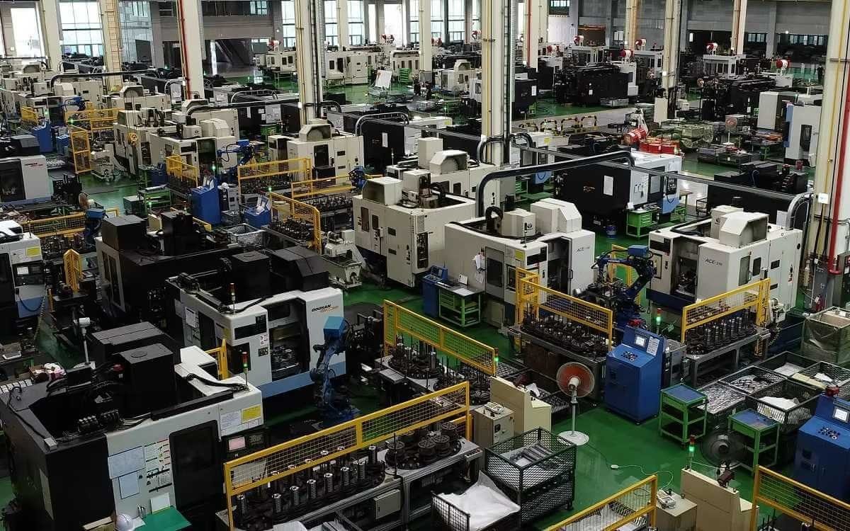
Yes, we are a manufacturer with our own factory.
Common models are in stock, and orders are usually shipped within 1–3 days.
5.Which payment methods are accepted?
We accept T/T, L/C, PayPal, VISA, Western Union, Apple Pay, Google Pay, Afterpay (Clearpay), Klarna, and Trade Assurance.
For full orders: 30% deposit, balance before shipment.
For small/sample orders: full payment in advance.
6.How will you deliver my goods?
We offer flexible shipping options: DHL, UPS, FedEx, TNT, EMS, as well as air or sea freight.
All deliveries ensure door-to-door fast and safe service.
7.How do you inspect and guarantee your products?
All products are tested before shipment to ensure perfect working condition.
We offer a 12-month warranty — if a product fails due to quality issues, we provide free spare parts or repair support.
8.What about after-sales service?
If you encounter any problem during use, please contact your sales manager or our support team at any time.
We will respond quickly and help solve the issue efficiently.
9.What are your main applications?
- Hydraulic systems
- Agricultural machinery
- Construction machinery
- Automobile industry
- Local distributors and maintenance centers
10.Can I get a discount for bulk orders?
Yes. We offer competitive wholesale prices and try our best to give benefits to long-term partners.
Shoot Us An Email
Professional Manufacturer