Product Overview
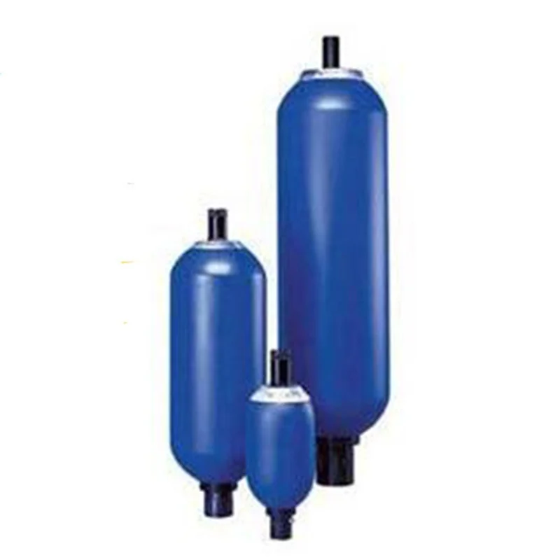
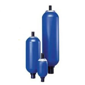
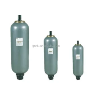
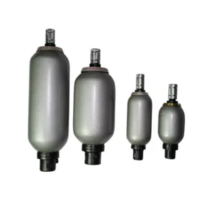
The NXQAB-80/10-L-Y, NXQAB-80/20-L-Y and NXQAB-80/31.5-L-Y are 80-liter NXQAB bladder accumulators designed for hydraulic energy storage and transient-flow management.
All three models share the same basic configuration:
- NXQAB: bladder accumulator with AB large-opening structure
- 80: 80 L nominal volume
- L: threaded hydraulic connection
- Y: hydraulic oil
The key difference is the nominal pressure:
- NXQAB-80/10-L-Y: 10 MPa / 100 bar
- NXQAB-80/20-L-Y: 20 MPa / 200 bar
- NXQAB-80/31.5-L-Y: 31.5 MPa / 315 bar
Public NXQ documentation lists all three configurations as standard NXQAB products. The model-code system defines structure, volume, pressure, connection and working medium.
The NXQ family originates from China’s standardized bladder-accumulator pressure-vessel system. GB/T 20663-2006 has been replaced by GB/T 20663-2017, so current product documentation should reference the current accumulator pressure-vessel standard rather than presenting the 2006 edition as the current standard.
Our replacement accumulators are matched according to the complete model code, nominal volume, pressure class, AB hydraulic structure and threaded connection, with 100% simulated operating-condition testing for pressure integrity, sealing, pre-charge stability and charge/discharge performance.
Technical Specifications
NXQAB-80/10-L-Y
- Product Type: Bladder Accumulator
- Series: NXQAB
- Complete Model: NXQAB-80/10-L-Y
- Structure: AB Type / Large Opening
- Nominal Volume: 80 L
- Nominal Pressure: 10 MPa
- Pressure Equivalent: 100 bar
- Hydraulic Connection: Threaded
- Connection Code: L
- Working Medium: Hydraulic Oil
- Gas Medium: Nitrogen
- Operating Principle: Gas-liquid separation by bladder
- Displacement: Not applicable
- Rotational Speed: Not applicable
The complete model is listed in public NXQAB product documentation.
NXQAB-80/20-L-Y
- Product Type: Bladder Accumulator
- Series: NXQAB
- Complete Model: NXQAB-80/20-L-Y
- Structure: AB Type / Large Opening
- Nominal Volume: 80 L
- Nominal Pressure: 20 MPa
- Pressure Equivalent: 200 bar
- Hydraulic Connection: Threaded
- Connection Code: L
- Working Medium: Hydraulic Oil
- Gas Medium: Nitrogen
- Operating Principle: Gas-liquid separation by bladder
- Displacement: Not applicable
- Rotational Speed: Not applicable
This configuration is listed in the published NXQAB model range.
NXQAB-80/31.5-L-Y
- Product Type: Bladder Accumulator
- Series: NXQAB
- Complete Model: NXQAB-80/31.5-L-Y
- Structure: AB Type / Large Opening
- Nominal Volume: 80 L
- Nominal Pressure: 31.5 MPa
- Pressure Equivalent: 315 bar
- Hydraulic Connection: Threaded
- Connection Code: L
- Working Medium: Hydraulic Oil
- Gas Medium: Nitrogen
- Operating Principle: Gas-liquid separation by bladder
- Displacement: Not applicable
- Rotational Speed: Not applicable
The complete model is included in the public NXQAB series model list.
Reference Dimensions for the 80 L / 31.5 MPa Configuration
Public NXQ technical documentation reports the following reference configuration for an 80 L / 31.5 MPa NXQ accumulator:
- Nominal Volume: 80 L
- Main Diameter: approximately 299 mm
- Threaded Overall Length: approximately 1810 mm
- Flanged Overall Length: approximately 1825 mm
- Approximate Weight: 213 kg
- Connection: Threaded or flanged depending on configuration
These are reference dimensions for the standard NXQ 80 L / 31.5 MPa configuration, not an independently verified OEM drawing for every manufacturer of the NXQAB model. Final dimensions should therefore be confirmed against the actual manufacturer’s drawing and nameplate.
For the 10 MPa and 20 MPa versions, the enclosure dimensions should not be copied from the 31.5 MPa version without verification because pressure class can affect vessel construction and dimensions.
Engineering Interpretation of the Model Code
NXQAB
Identifies the NXQ bladder accumulator family with the AB large-opening structure.
Public NXQ documentation distinguishes:
- A: Small Opening
- AB: Large Opening
Therefore, NXQA and NXQAB are not merely different abbreviations; they represent different hydraulic opening configurations.
80
Indicates:
80 L Nominal Volume
This is the geometric nominal volume of the accumulator and should not be interpreted as the amount of usable hydraulic oil available in a pressure cycle.
10 / 20 / 31.5
These identify the pressure class:
- 10 MPa = 100 bar
- 20 MPa = 200 bar
- 31.5 MPa = 315 bar
The three pressure classes should not be treated as interchangeable.
L
Indicates:
Threaded Hydraulic Connection
Y
Indicates:
Hydraulic Oil
Therefore:
NXQAB-80/31.5-L-Y = 80 L / 31.5 MPa / AB Large Opening / Threaded Connection / Hydraulic Oil.
Key Technical Advantages
80 L High-Capacity Energy Storage
The 80-liter nominal volume provides a large hydraulic energy-storage capacity suitable for larger hydraulic power units and systems with high transient-flow requirements.
Actual usable hydraulic volume depends on:
- Minimum operating pressure
- Maximum operating pressure
- Nitrogen pre-charge
- Operating temperature
- Gas compression process
- Cycle characteristics
AB Large-Opening Structure
The AB configuration uses the large-opening design defined in the NXQ model system. This structure is suitable for applications requiring higher transient hydraulic flow, subject to the actual port, piping and valve configuration.
Three Standard Pressure Classes
The same 80 L platform is available in:
- 10 MPa
- 20 MPa
- 31.5 MPa
This allows equipment designers to select the pressure-vessel configuration according to the actual hydraulic-system pressure.
Gas-Liquid Separation
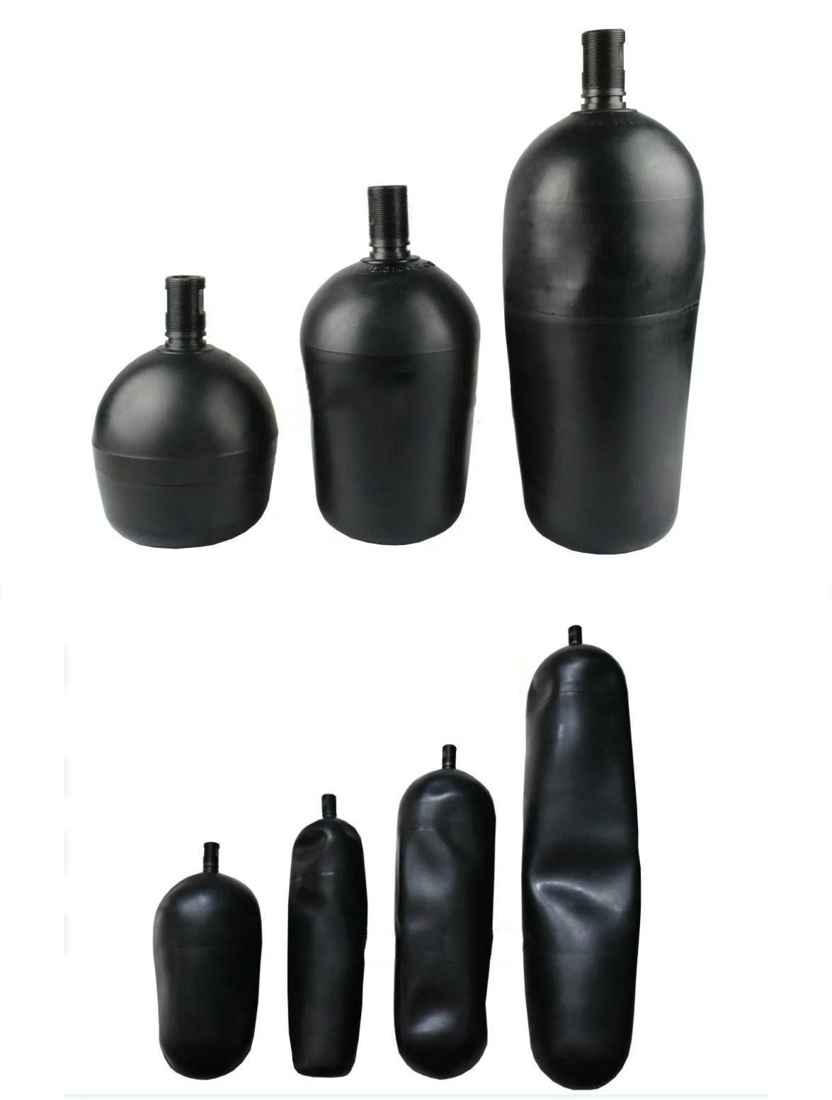
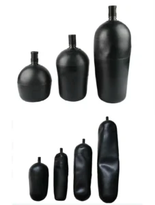
The bladder separates hydraulic oil from nitrogen.
During charging:
Oil Enters → Nitrogen Compresses → Energy Stored
During discharge:
Nitrogen Expands → Oil Returns → Stored Energy Released
This provides rapid hydraulic energy exchange during transient system conditions.
Multi-Function Hydraulic Control
NXQ technical literature identifies applications including:
- Energy storage
- Emergency operation
- Force equilibrium
- Leakage compensation
- Volume compensation
- Shock absorption
- Pulsation damping
- Flow-fluctuation reduction
Standardized Model Identification
The NXQ model code directly identifies the basic engineering configuration, helping buyers distinguish volume, pressure class, hydraulic connection and working medium during procurement.
Application Areas
- Hydraulic Power Units
- Hydraulic Presses
- Steel Processing Machinery
- Metal Forming Systems
- Large Machine Tools
- Hydraulic Test Benches
- Construction Machinery
- Mining Equipment
- Material Handling Machinery
- Agricultural Machinery
- Forestry Equipment
- Emergency Hydraulic Power Systems
- Peak-Flow Compensation Circuits
- Pressure Maintenance Systems
- Hydraulic Shock Absorption
- Pump Pulsation Damping
Expert Maintenance Tips
Match the Pressure Class Exactly
The three models are not interchangeable:
- NXQAB-80/10-L-Y: 10 MPa
- NXQAB-80/20-L-Y: 20 MPa
- NXQAB-80/31.5-L-Y: 31.5 MPa
Even with the same 80 L nominal volume, the pressure-vessel design requirements differ.
Calculate Nitrogen Pre-Charge for the Actual Application
Do not set pre-charge simply as a percentage of the accumulator’s nominal pressure.
The calculation should consider:
- Minimum system pressure
- Maximum system pressure
- Required usable oil volume
- Cycle time
- Operating temperature
- Isothermal or adiabatic compression
Published NXQ technical documentation notes that slower cycles may be treated as approximately isothermal while fast cycles require consideration of adiabatic compression behavior.
Charge with Nitrogen Only
Use nitrogen (N₂) for the gas side.
Do not use oxygen or compressed air.
Provide Independent Mechanical Support
An 80 L accumulator should be mechanically secured with suitable clamps, brackets and structural supports. Hydraulic piping should not be used as the primary mechanical support.
Fully Depressurize Before Service
Recommended service sequence:
Isolate → Depressurize → Verify Zero Pressure → Discharge Gas → Service
The accumulator may retain significant stored hydraulic energy after the pump has stopped.
Inspect the Bladder and Gas Valve
Inspect the bladder and gas-side components if:
- Pre-charge pressure drops rapidly
- Hydraulic pressure oscillation increases
- Stored-energy performance decreases
- Shock absorption becomes weaker
- Charge/discharge response changes
- Gas leakage is observed
Verify the Hydraulic Connection
The L code specifies a threaded connection. It should not be replaced by an F-code flanged configuration without checking the complete hydraulic installation.
Perform Full Replacement Testing
Recommended validation includes:
- Pressure-vessel inspection
- Hydraulic pressure test
- Leakage test
- Gas-valve sealing test
- Bladder integrity check
- Nitrogen pre-charge verification
- Connection dimensional inspection
- Charge/discharge simulation
- Final safety inspection
Our replacement units can be subjected to 100% simulated operating-condition testing to verify pressure integrity, sealing performance and hydraulic response before shipment.