

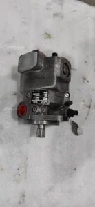


Product Overview
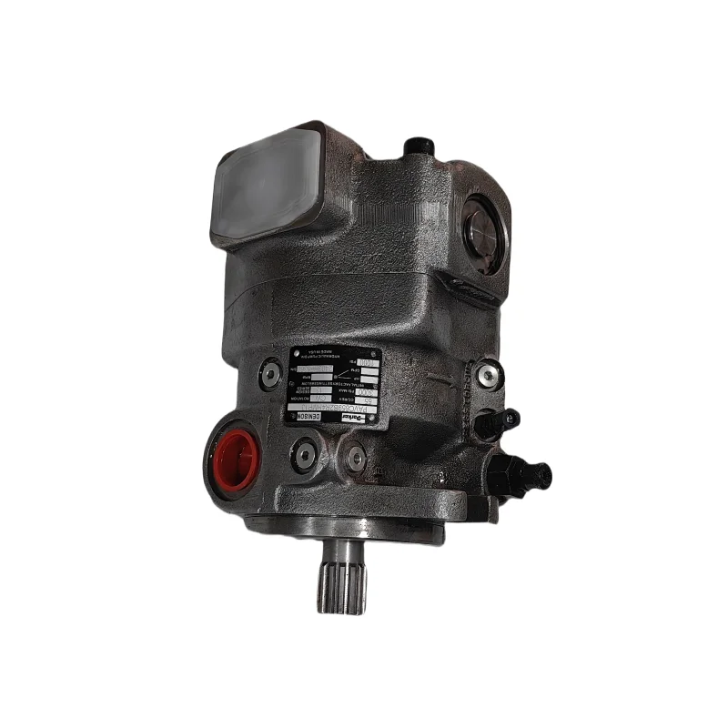
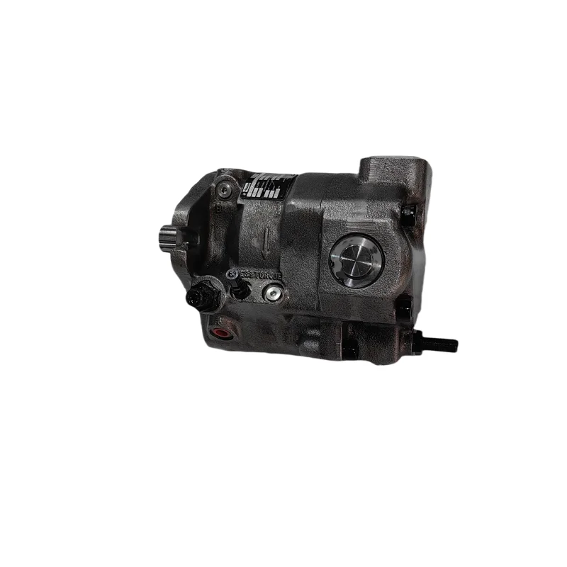
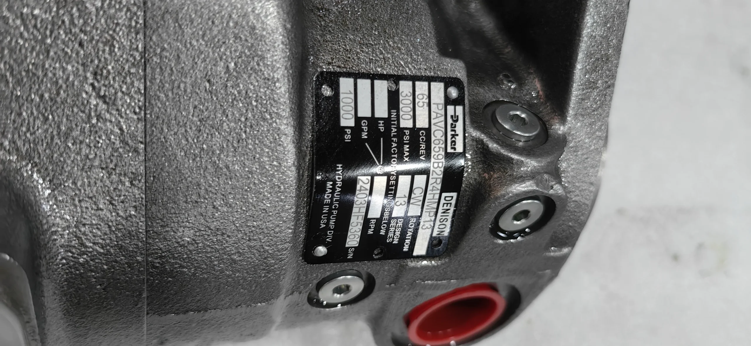
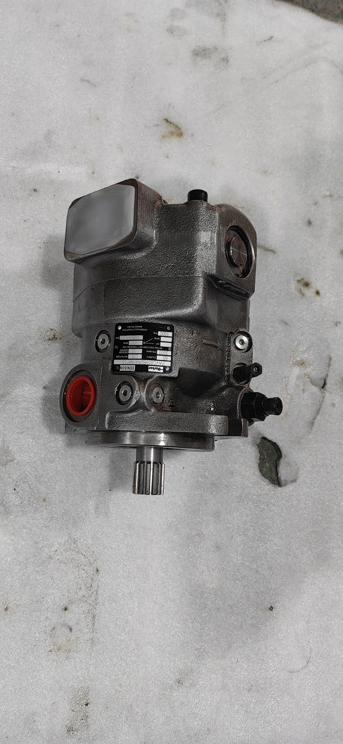
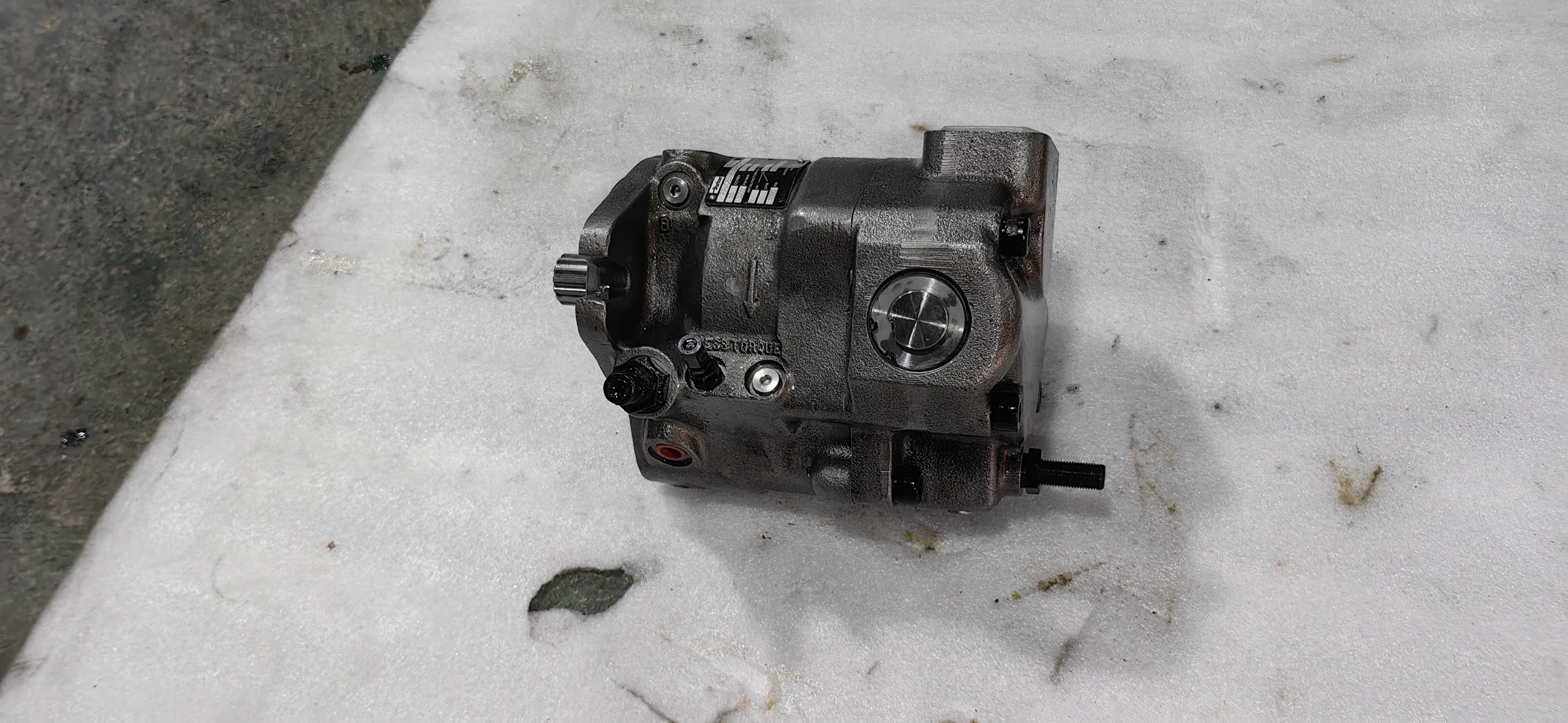
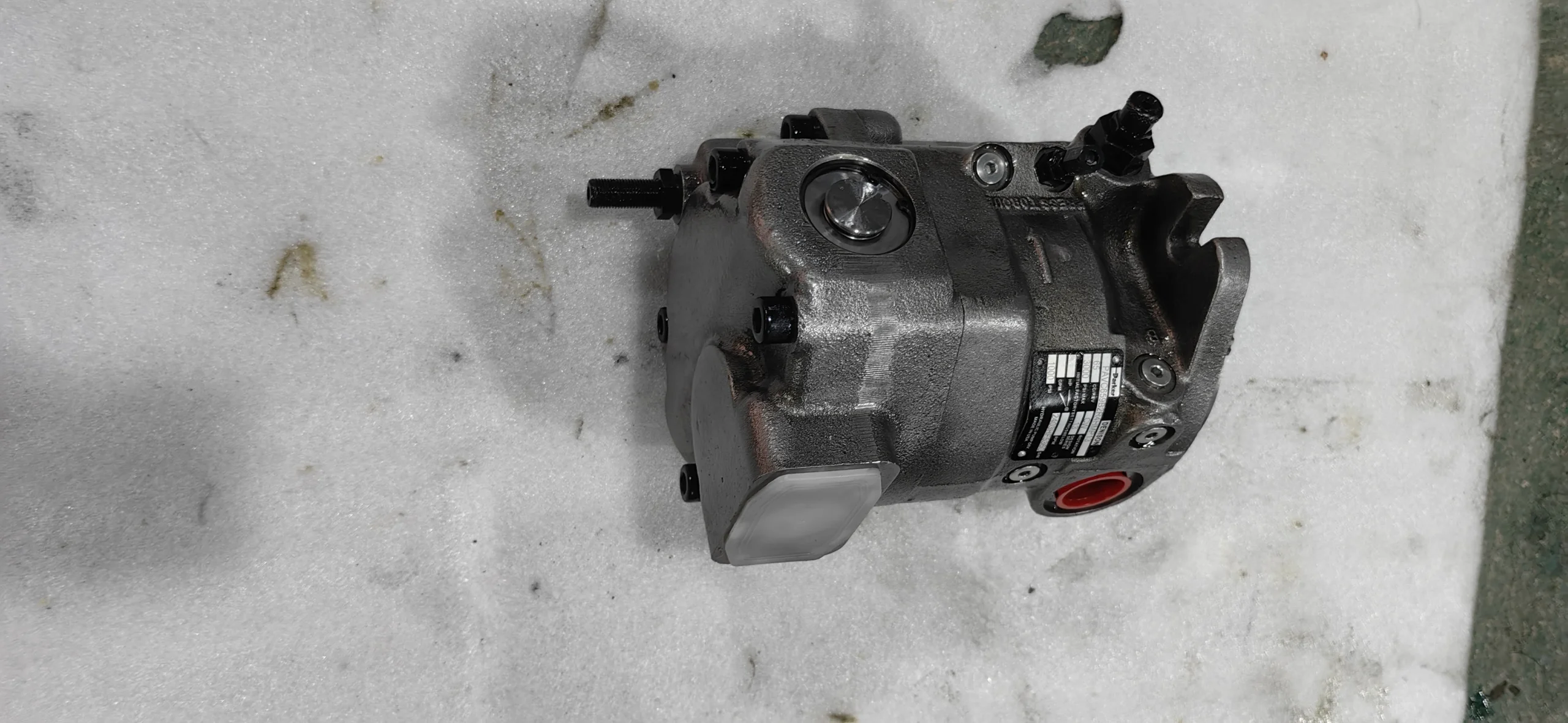
The PAVC659B2R4HMP13 is a Parker Hannifin PAVC65 variable displacement axial piston pump and a historical PAVC65 Series 13 configuration. Parker’s official PAVC65 documentation specifies a 65 cm³/rev displacement, 207 bar / 3000 psi continuous outlet pressure, 248 bar / 3600 psi peak pressure, and a 600–3000 rpm speed rating. At 1800 rpm and maximum displacement, Parker publishes 118.1 L/min reference pump delivery and 43.1 kW / 57.8 hp reference input power at 207 bar.
The model code is particularly important because this is not merely a generic PAVC65:
PAVC659B2R4HMP13
identifies a specific historical configuration with dual bearings, SAE C 14-tooth spline shaft, side-flange inlet, clockwise rotation, adjustable differential, HM remote pressure and power control, paint, and Series 13 identification. Parker’s official PAVC conversion documentation also confirms PAVC65 Series 13 as a legacy series.
For aftermarket replacement, compatibility should therefore be verified against the complete model code rather than the PAVC65 family number alone. Our replacement program is based on in-place interchangeability supported by 100% simulated working-condition testing.
Technical Specifications
PAVC659B2R4HMP13
- Brand: Parker Hannifin
- Series: PAVC
- Historical Series: PAVC65 Series 13
- Complete Model: PAVC659B2R4HMP13
- Product Type: Variable Displacement Axial Piston Pump
- Displacement: 65 cm³/rev
- Displacement: 4.0 in³/rev
- Continuous Outlet Pressure: 207 bar / 3000 psi
- Peak Outlet Pressure: 248 bar / 3600 psi
- Speed Rating: 600–3000 rpm
- Reference Delivery at 1800 rpm: 118.1 L/min / 31.2 GPM
- Reference Input Power at 1800 rpm, Maximum Displacement and 207 bar: 43.1 kW / 57.8 hp
- Operating Temperature: −40°C to +71°C
- Housing: Cast iron
- Reference Weight: 28 kg / 62 lb
- Mounting: SAE C 2-bolt flange or diagonal SAE C 4-bolt flange.
Model Code Interpretation
The historical ordering code can be read as:
- PAVC — Parker axial piston variable controllable pump family
- 65 — 65 cm³/rev
- 9 — Dual bearing
- B — SAE C 14-tooth splined shaft, 12/24 pitch
- 2 — PAVC65 inlet option, side-flange arrangement
- R — Right-hand / clockwise rotation, viewed from the shaft end
- 4 — Adjustable differential
- HM — Remote Pressure & Power control
- P — Painted
- 13 — Historical PAVC65 Series 13 identification
- Seal code omitted — Nitrile standard seal configuration.
Shaft Configuration
The B shaft option is:
- SAE C spline
- 14 teeth
- 12/24 pitch
- Maximum published torque: 641 N·m / 5680 in-lb
The 9 dual-bearing option is intended for applications where side loading may occur, with Parker specifying a maximum side load of 113.4 kg / 250 lb.
Differential Adjustment
The 4 code identifies an Adjustable Differential configuration. Parker specifies a sensitivity of 13.8 bar / 200 psi per turn for PAVC33/38/65 pumps.
HM Control Configuration
The most significant engineering feature of PAVC659B2R4HMP13 is the HM control.
Parker defines HM as:
Remote Pressure & Power
This combines:
Remote Pressure Compensation + Power/Torque Limiting
Parker’s H control uses mechanical feedback from the servo-piston position to reduce pump displacement and therefore reduce hydraulic output power as the power-control condition is reached.
The M control allows remote control of output pressure through the low-signal B port.
The combined HM architecture therefore allows:
- Remote pressure control
- Power/torque limitation
- Mechanical displacement feedback
- Automatic destroking when the corresponding control condition is reached
This makes HM substantially different from a standard pressure-compensated PAVC65.
HM Power-Setting Clarification
Parker’s ordering notes are important for this exact configuration.
For power-controlled pumps using H, C, HM or CM, Parker requires the maximum input power specification to be defined together with drive speed and compensator pressure. When no special power limit is specified, the published default for HM/CM is:
60 hp at 1800 rpm and 3000 psi. (
Therefore, the correct product-page statement is:
HM remote pressure and power control; final power setting is application/configuration dependent. Parker’s catalog default for HM/CM without a specified power limit is 60 hp at 1800 rpm and 3000 psi.
It should not be presented as a fixed 60 hp rating for every physical PAVC659B2R4HMP13 unit.
Key Technical Advantages
1. 65 cm³/rev High-Speed Variable Displacement Platform
The PAVC65 provides 65 cm³/rev displacement and a 600–3000 rpm speed rating. Parker notes that applications above 2700 rpm should consider a dual-inlet configuration and the applicable inlet-characteristics curve.
2. Built-In Supercharger
A built-in supercharger is one of Parker’s listed PAVC design features and supports the pump’s high-speed capability. Actual high-speed performance remains dependent on inlet pressure, inlet restriction, fluid condition and installation geometry.
3. Dual-Bearing Shaft Configuration
The 9 option provides dual bearings for applications where side loading may occur. Parker specifies a maximum side load of 113.4 kg / 250 lb for this option.
4. SAE C 14-Tooth Spline Shaft
The B shaft option provides a 14-tooth SAE C spline, 12/24 pitch, with a published maximum torque of 641 N·m. This creates a standardized coupling interface for industrial drive systems.
5. HM Remote Pressure and Power Control
The HM configuration combines remote pressure control through the low-signal B port with mechanical power-control feedback. Parker’s documentation describes both control mechanisms as influencing the servo and swash-plate position.
This allows the pump to respond to both:
Hydraulic pressure demand + prime-mover power limitation
6. Field-Changeable Cartridge Controls
Parker identifies PAVC cartridge controls as field changeable, supporting service and configuration flexibility in legacy industrial hydraulic systems.
7. Replaceable Bronze-Clad Port Plate
Parker specifies a replaceable bronze-clad port plate, a serviceable component at a critical hydraulic distribution/sliding interface within the axial piston rotating group.
8. Hydrodynamic Cylinder-Barrel Bearing
The hydrodynamic cylinder-barrel bearing supports stable rotation of the cylinder barrel under operating loads and is listed as a standard PAVC65 design feature by Parker.
9. Low Flow Ripple and Controlled Noise
Parker’s published PAVC65 performance data provides reference flow, efficiency and noise information. At 1800 rpm, the published A-weighted reference sound-pressure levels across the stated 500–3000 psi range are approximately 77–81 dB(A). Parker notes that actual field noise depends on mounting, tank construction and plant layout.
10. Service-Friendly Two-Piece Housing
The two-piece housing, field-changeable controls, replaceable port plate and dedicated service information make the PAVC platform suitable for professional rebuild and replacement programs.
Application Areas
The PAVC659B2R4HMP13 configuration should be selected based on its actual control and mechanical configuration rather than on displacement alone.
Typical application environments include:
- Industrial hydraulic power units
- Hydraulic systems requiring remote pressure control
- Constant-speed prime-mover systems requiring power limitation
- Belt-driven hydraulic pumps
- Chain-driven hydraulic pumps
- Universal-joint drive systems
- Foot-mounted pump installations
- Heavy-duty industrial hydraulic circuits
- High-speed variable-flow hydraulic systems
Parker’s ordering documentation specifically identifies belt/chain drive, universal-joint drive, massive couplings and foot-mount installations as typical applications for the dual-bearing option.
Expert Maintenance Tips
1. Do not treat 248 bar as continuous pressure
PAVC65 is specified at:
- 207 bar continuous
- 248 bar peak
The peak rating is not a continuous-duty setting.
2. Distinguish 1800-rpm reference performance from 3000-rpm operation
The PAVC65 speed rating reaches 3000 rpm, but Parker specifically points to inlet-characteristics data and recommends consideration of dual-inlet porting for applications above 2700 rpm.
3. Control inlet pressure and vacuum
Parker specifies:
- Maximum inlet pressure: 1.72 bar / 25 psi
- Minimum inlet condition at 1800 rpm: 0.17 bar / 5 in.Hg vacuum
Higher-speed operation should be checked against the inlet characteristics.
4. Keep control-drain back pressure low
The PAVC control-drain limit is 7 bar / 100 psi. Parker also specifies a much lower 0.28 bar / 4 psi limit for the built-in airbleed drain line.
5. Reconfirm the HM power setting
For PAVC659B2R4HMP13, verify:
- Drive speed
- Compensator pressure
- Maximum input power
- Remote pressure signal
- Swash-plate response
- Destroking point
Parker requires power-controlled pumps to be specified by drive speed, compensator pressure and maximum input-power limit.
6. Verify shaft coupling torque
The B shaft is rated at 641 N·m maximum published torque. Check spline engagement, alignment, coupling geometry and peak startup torque before commissioning.
7. Do not interpret dual bearings as unlimited side-load capacity
The 9 bearing option has a stated maximum side load of 113.4 kg / 250 lb. Belt and chain applications should therefore be checked against the actual pulley/sprocket geometry.
8. Control fluid viscosity and temperature
Parker specifies:
- Recommended viscosity at 38°C: 30–50 cSt
- Normal operating viscosity: 17–180 cSt
- Maximum startup viscosity: 1000 cSt
- Consult Parker above 71°C operating temperature.
9. Maintain hydraulic cleanliness
Parker recommends protection to SAE Class 4 / ISO 16/13, with ISO 18/15 as the maximum recommended reference. Parker also recommends a correctly sized in-tank suction strainer rather than an unnecessarily restrictive suction-line filter.
10. Prime and bleed before startup
Parker’s startup procedure calls for:
- Filling the case with oil
- Reducing pressure
- Opening the circuit or bleeding the pump outlet
- Using the built-in airbleed during initial startup
The airbleed is standard on the PAVC33/38/65/100 families.
11. Verify shaft alignment
Parker specifies a maximum pump/motor shaft alignment of 0.010 TIR when using a standard floating coupling and warns against end thrust on the pump shaft.
12. Apply 100% simulated working-condition testing
For a verified replacement PAVC659B2R4HMP13, final testing should include:
- Low-speed startup
- 1800-rpm reference test
- High-speed inlet-condition verification
- 65 cm³/rev displacement verification
- Reference-flow verification
- 207-bar continuous-pressure test
- 248-bar peak-pressure verification
- Remote-pressure control response
- Power/torque-control response
- HM interaction test
- Shaft/rotation verification
- Control-drain leakage
- Temperature rise
- Sustained-load stability
For this configuration, the essential acceptance logic is:
Remote Pressure + Power Limitation + Swash-Plate Response
rather than a single static pressure measurement.
Related Models:
PARKER PARKER plunger pump model has: 16, 23, 32, 46, 76, 100, plunger pump model PV016, PV020, PV080, PV032, PV046, PV092,
PV0140, PV180, PV270, and other series models
PV180R1K4T1NUPG, PV180R1K4T1N100, PV180R1K4T1N2LB, PV180R1L1T1NFFC, PV180R1L1T1NFPV, PV180R1L1T1NSLB, PV180R1L1T1NUPG,
PV180R1L1T1NZLC, PV180R1L4T1NFFC, PV180R1L4T1N100, PV180R2K1T1NFWS, PV270L1K1T1NFHS, PV270L1K1T1NFRC, PV270L1K1T1V2LC,
PV270L1L1T1NFRC, PV270R1K1A1NTLB, PV270R1K1B1NFFC, PV270R1K1B1NFRC, PV270R1K1B1NYLC, PV270R1K1T1NFFC, PV270R1K1T1NFFP,
PV270R1K1T1NFF1, PV270R1K1T1NFHS, PV270R1K1T1NFPV, PV270R1K1T1NFRC, PV270R1K1T1NFRD, PV270R1K1T1NFRP, PV270R1K1T1NFR1,
PV270R1K1T1NFT1, PV270R1K1T1NFWS, PV270R1K1T1NTCC, PV270R1K1T1NTLA, PV270R1K1T1NTLC PV270R1K1T1NUCC, PV270R1K1T1NULA,
PV270R1K1T1NULC, PV270R1K1T1NUPE, PV270R1K1T1NUPG, PV270R1K1T1NWLA, PV270R1K1T1NWLB, PV270R1K1T1NWLC, PV270R1K1T1NWLD,
PV270R1K1T1NYCB, PV270R1K1T1NYCC, PV270R1K1T1NYLA, PV270R1K1T1NYLB, PV270R1K1T1NYLC, PV270R1K1T1NZCC, PV270R1K1T1NZCD,
PV270R1K1T1NZLC, PV270R1K1T1N001, PV270R1K1T1N2CC, PV270R1K1T1N2CD, PV270R1K1T1N2LB, PV270R1K1T1N2LC, PV270R1K1T1N2LD,
PV270R1K1T1N3LC, PV270R1K1T1VYLC, PV270R1K1T1V2LC, PV270R1K1T1WFDS, PV270R1K1T1, PV270R1K1T1WYLD, PV270R1L1T1NFFC,
PV270R1L1T1NFF1, PV270R1L1T1NFPV, PV270R1L1T1NUPG, PV270R1L1T1NWCC, PV270R1L1T1NZLC, PV270R1L1T1N2LB, PV270R1L1T1N3LC,