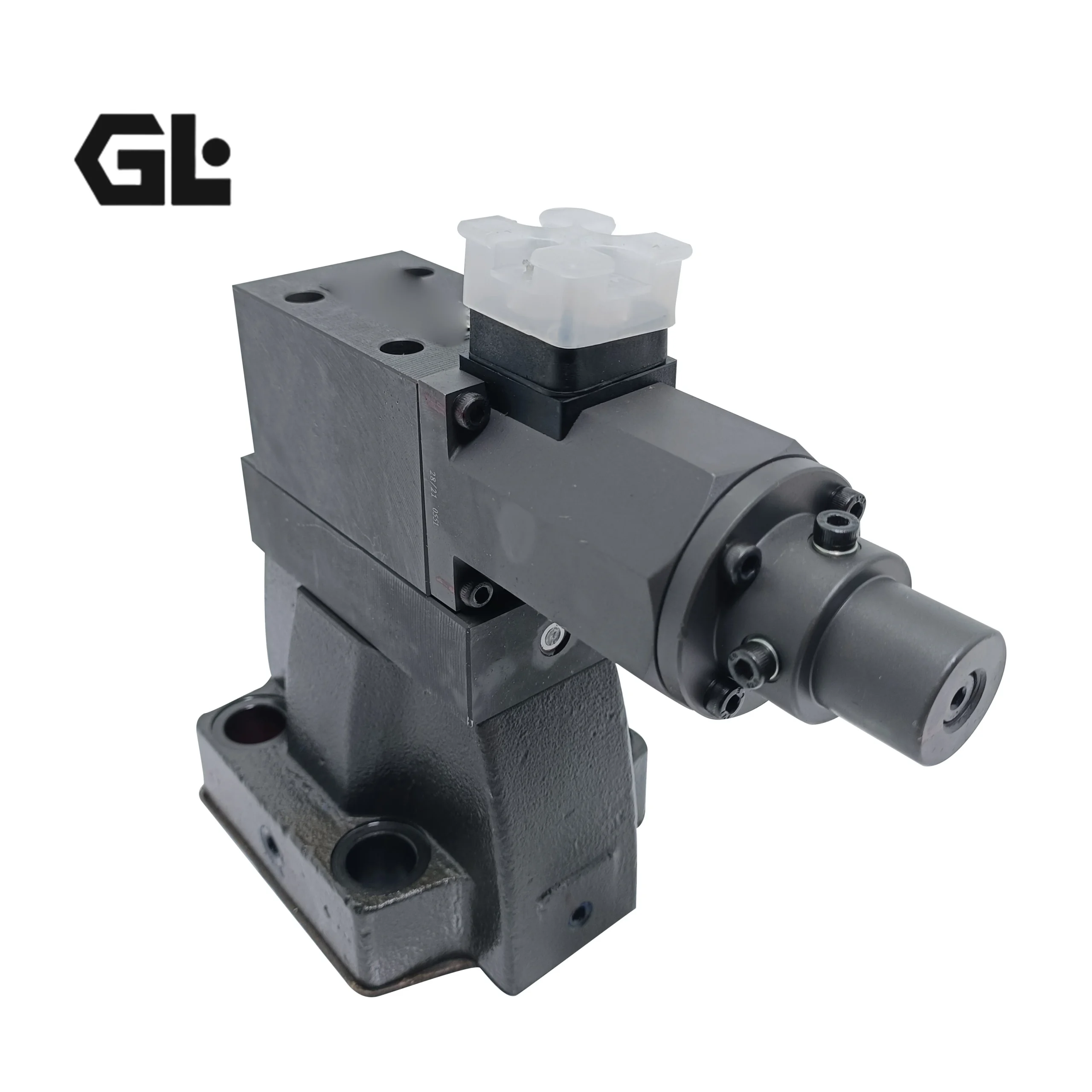


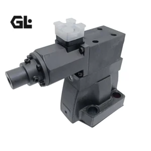
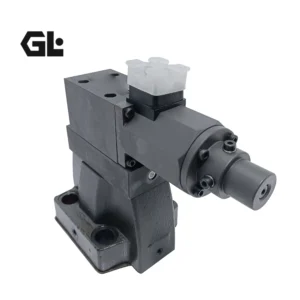
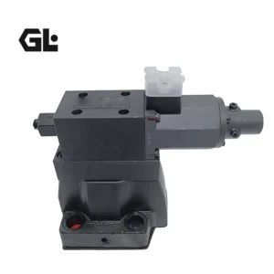
PROPORTIONAL ELECTRO-HYDRAULIC PRESSURE CONTROL VALVE EBG-03-C-R-20 EBG-03-H-R-20 EBG-06-C/H-R-20 HYDRAULIC VALVE
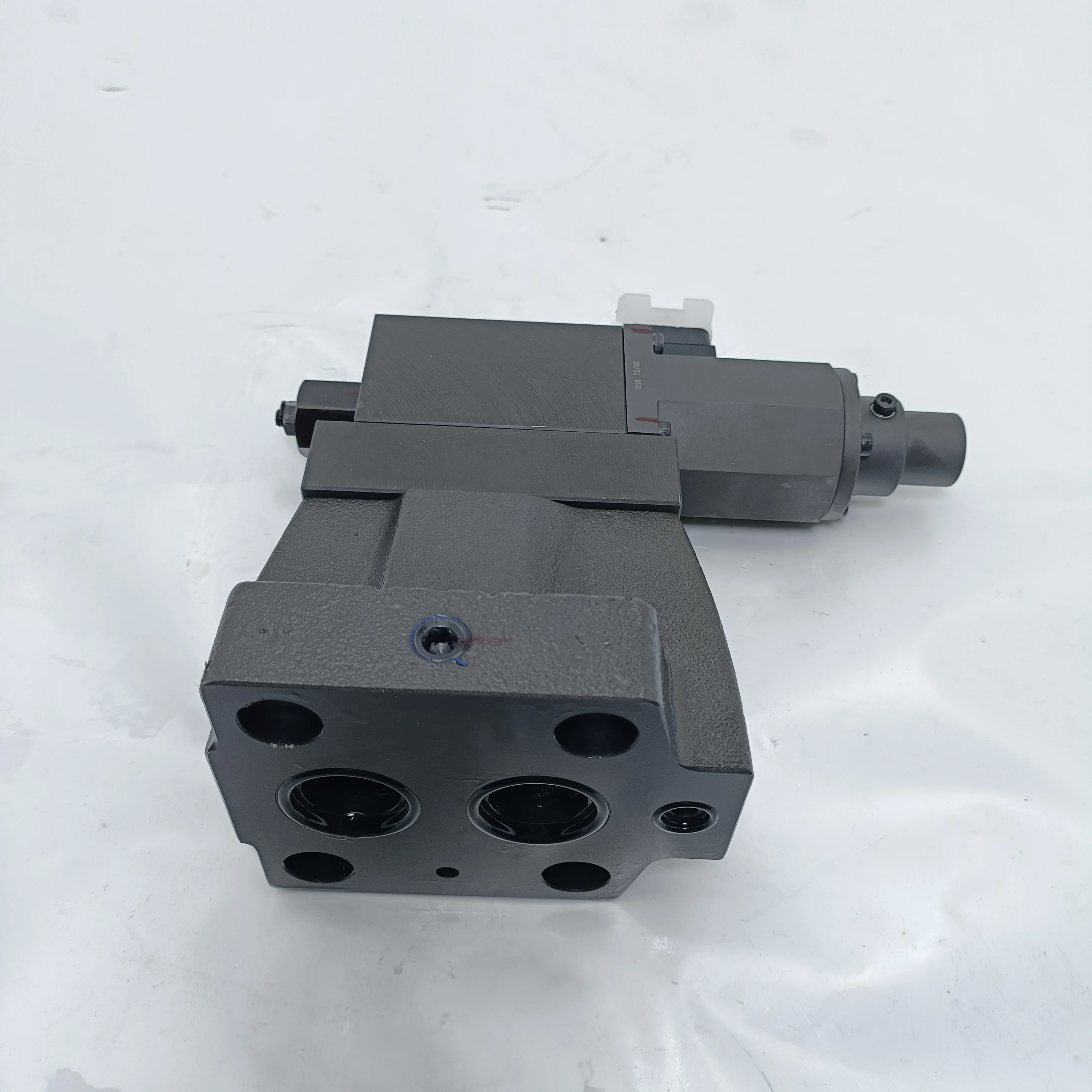
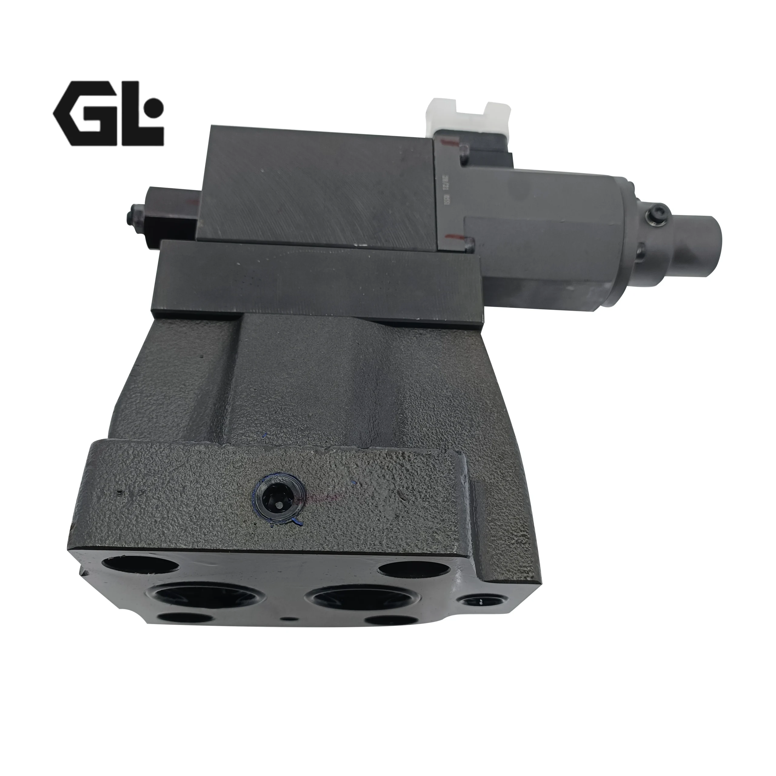
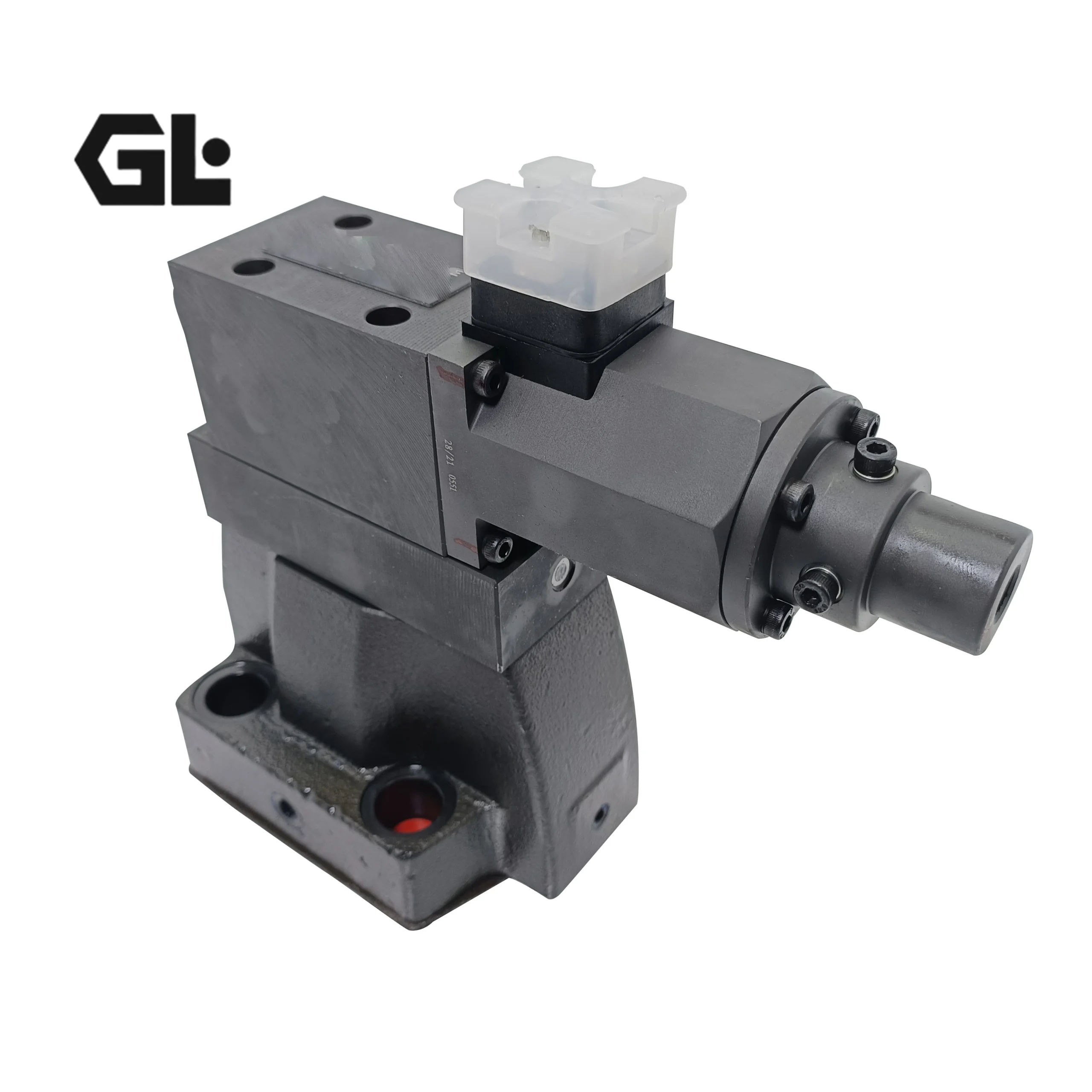
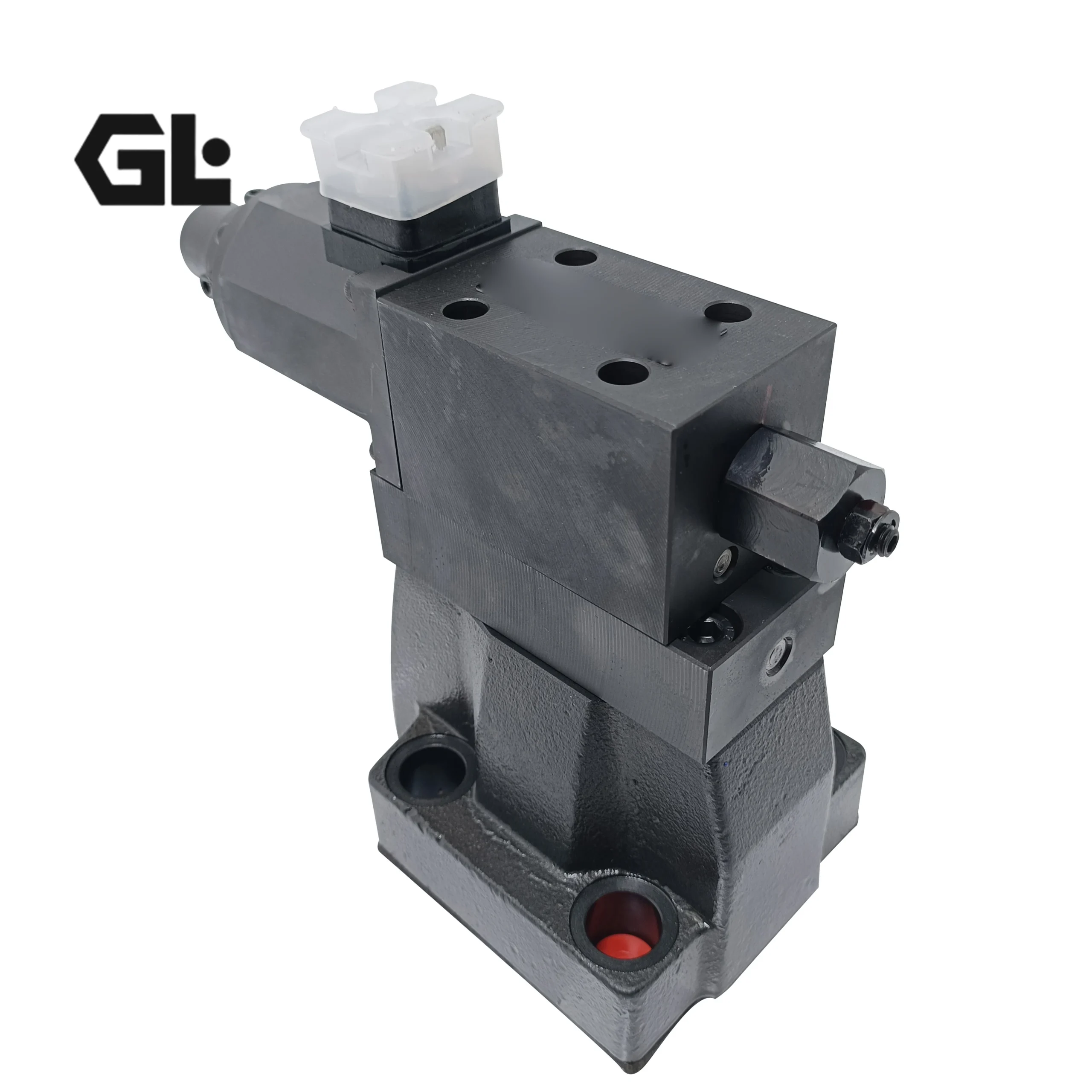
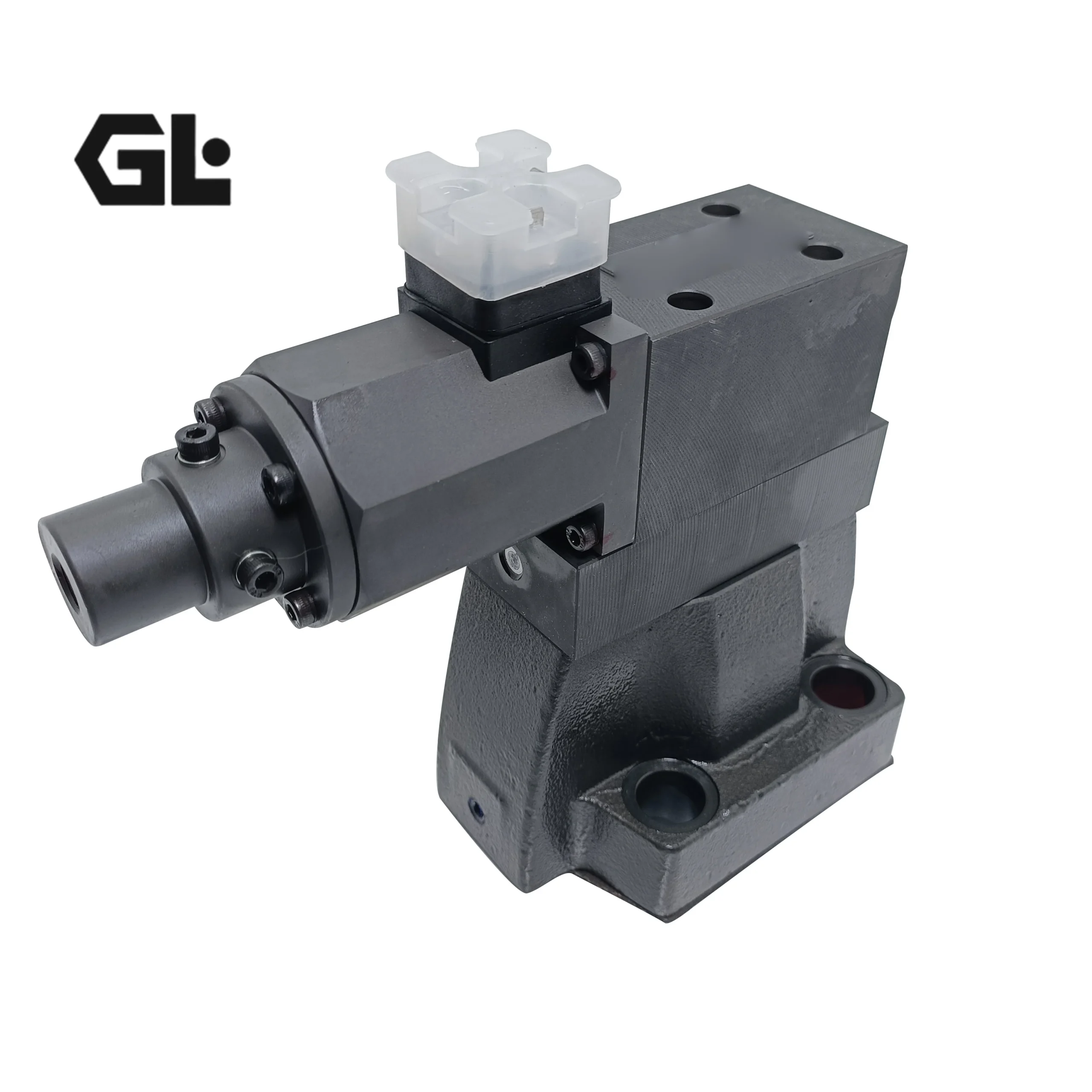
EBG-03-C-R-20 is a pilot-operated electro-hydraulic proportional relief valve, often used for high-precision pressure regulation in hydraulic systems. It is suitable for various medium and low-pressure hydraulic operating conditions. The following is a detailed explanation from multiple dimensions and lists the complete models of this series:
Model Analysis
EBG: Series code, representing pilot-operated electro-hydraulic proportional relief valve, which belongs to the category of hydraulic pressure control valves
03: Diameter specification code, corresponding to the valve’s diameter specification of the 03 series, determines the valve’s basic flow capacity and is suitable for medium and small flow hydraulic systems
C: Control mode or valve core type code, representing the conventional control type valve core, suitable for pressure regulation requirements under standard working conditions, and distinguished from other codes such as H for scenarios with different pressure response characteristics
R: Installation or interface form code, referring to a specific plate-type installation adaptation structure that can be attached to the corresponding standard installation base plate to ensure sealing and stability after installation
20: Pressure parametry-related code, representing the valve’s suitable pressure regulation range or rated pressure-related parameters. The maximum suitable pressure is approximately 20 mpa for hydraulic systems (fine-tuned according to actual working conditions).
Core attribute
The type is pilot-operated electro-hydraulic proportional relief valve. The main body material is mostly cast iron, which has good pressure resistance and resistance to hydraulic oil corrosion, and is suitable for mainstream hydraulic media such as petroleum-based hydraulic oil.
The nominal pressure can generally reach 31.5MPa, and the working temperature range is usually -20 to 60℃, making it suitable for hydraulic systems in normal temperature and general industrial environments.
The installation form is mainly plate installation, which meets the adaptation requirements of the standardized installation base plate in the hydraulic system and is convenient for integration and replacement.
The drive mode is electromagnetic drive and it needs to be used in conjunction with a power amplifier to achieve precise conversion between electrical signals and hydraulic pressure.
Function and Role
Core function: Receive electrical signals and convert them into corresponding hydraulic control pressures. Adjust the opening degree of the main valve through the pilot mechanism to precisely control the maximum working pressure of the hydraulic system. It also has a pressure overflow function. When the system pressure exceeds the set value, it will automatically start the overflow to drain the excess oil back to the oil tank.
The main functions are as follows: Firstly, it provides stable pressure control for the hydraulic system, ensuring the smooth operation of the actuating elements and preventing abnormal equipment operation caused by pressure fluctuations. Second, it serves to provide overload protection, preventing the system pressure from being too high and damaging core components such as the pump body and pipelines. Thirdly, it can achieve stepless pressure regulation by adjusting the input electrical signal, adapting to the pressure requirements under different working conditions of the system.
Working principle
This valve adopts a pilot control structure and is divided into two parts: the pilot valve and the main valve. When in operation, an external electrical signal is input to the electromagnetic control terminal of the valve. The electromagnetic force drives the valve core of the pilot valve to act, thereby changing the pressure of the pilot oil circuit. The pressure change in the pilot oil circuit will drive the main valve core to move, adjusting the size of the overflow opening of the main valve. The system pressure is compared with the pressure corresponding to the set electrical signal through the feedback mechanism to form a closed-loop control. When the system pressure reaches the set value, the main valve remains stably open to achieve overflow pressure stabilization. If the system pressure is lower than the set value, the opening of the main valve will be reduced to decrease the overflow until the system pressure returns to the set range, thereby achieving precise and stable pressure control.
Installation Precautions
Before installation, the pipeline must be thoroughly flushed to remove iron filings, sealing residues and other impurities. At the same time, the cleanliness of the hydraulic oil should be checked to reach NAS level 7 or above. It is recommended to install a filter with a mesh size of ≥60 before the valve to prevent impurities from getting stuck in the valve core and affecting the regulation accuracy.
When installing the plate type, it is necessary to ensure that the surface finish of the installation is ≤4μm and the straightness is ≤0.01mm/mm. The bolts should be tightened with a rated torque wrench, and the force should be evenly distributed to avoid deformation of the installation surface and leakage.
When making electrical connections, a suitable power amplifier should be matched. The lead length should be controlled within 5 meters as much as possible. Check the voltage parameters and distinguish the positive and negative poles. The signal lines should be kept away from strong current circuits to prevent electromagnetic interference from causing signal distortion.
When connecting pipelines, avoid using sealing materials that are prone to fall off, such as sealing tapes. Instead, give priority to using suitable sealing gaskets. Keep the pipelines as short as possible and minimize the use of hoses to ensure system rigidity and reduce pressure response delay.
The installation position should preferably be close to the actuator or the pump outlet. It can be installed in any direction, but it is necessary to avoid the valve core axis being parallel to the acceleration direction of the equipment to prevent vibration from affecting the valve core’s operation.
Application scenarios and models used
Application scenarios: Widely used in hydraulic systems that require precise pressure regulation, such as injection molding, metal die-casting, machine tool processing, and hydraulic transmission equipment, etc. It is suitable for working environments with high requirements for pressure stability and the need to switch between multiple pressure conditions.
The types of machines used: Commonly found in injection molding machines, die-casting machines, CNC milling machines, hydraulic punch presses, small hydraulic testing machines, hydraulic baling machines and other equipment. It is also compatible with the auxiliary hydraulic circuits in some small construction machinery, such as the hydraulic control circuits of small loaders.
A complete list of EBG series models
This series of models forms multiple sub-models based on diameter, control mode, installation form, etc. The common complete models are as follows:
EBG – 03 – C – R – 20
EBG – 03 – H – 10
EBG – 03 – B – 50
EBG – 03 – C – T
EBG – 03 – H – T
EBG – 06 – C – 60T
EBG – 06 – H – 51
EBG – 06 – B – L
EBG – 10 – C – S – 30
EBG – 10 – H
EBG – 06 – C – R – 30
EBG – 10 – C – T
EBG – 06 – H – 61Y
EBG – 03 – A – 20
EBG – 10 – H – T
EBG-03 series
Ebg-03-c, EBG-03-H, EBG-03-C-T, EBG-03-H-T, EBG-03-C-R, EBG-03-H-R, EBG-03-C-L, EBG-03 -H-L, EBG-03-A45-R, EBG-03-B-50, EBG-03-H-10, EBG-03-C-R-20
EBG-06 series
EBG-06-C, EBG-06-H, EBG-06-C-T, EBG-06-H-T, EBG-06-C-L, EBG-06-H-R, EBG-06-B, EBG-06-BH -L, EBG-06-H-51, EBG-06-H-60T, EBG-06-H-61Y, EBG-06-C-T-51, EBG-06-C-R-30
EBG-10 series
EBG-10-C, EBG-10-H, EBG-10-C-T, EBG-10-H-T, EBG-10-H-R, EBG-10-C-S-30