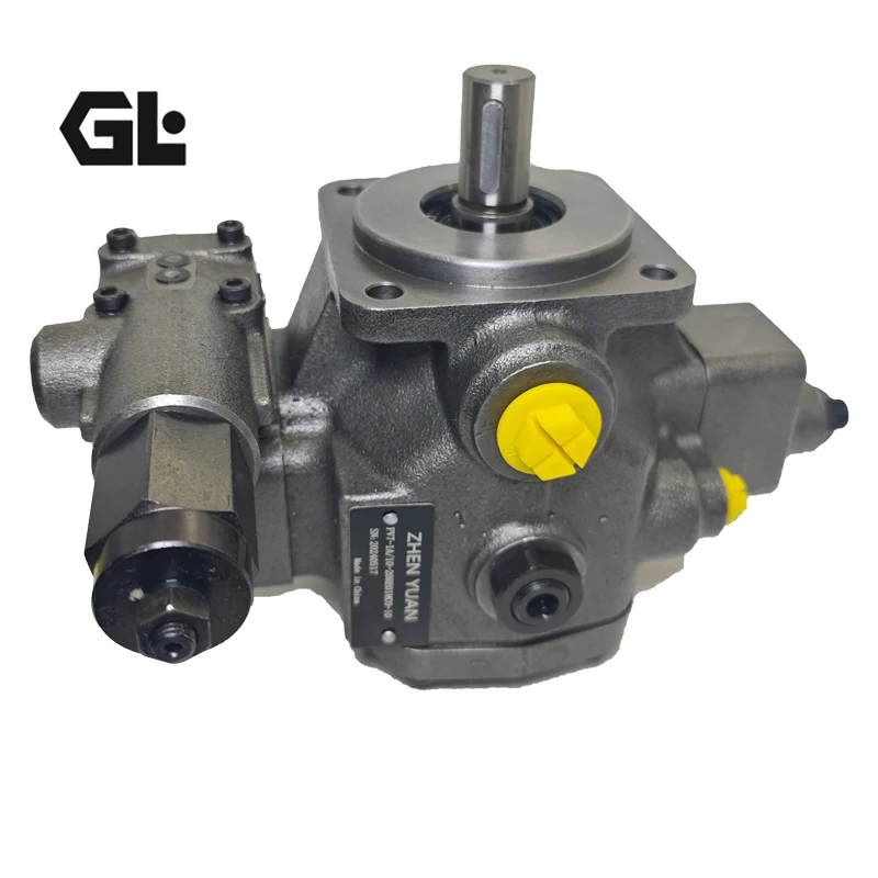

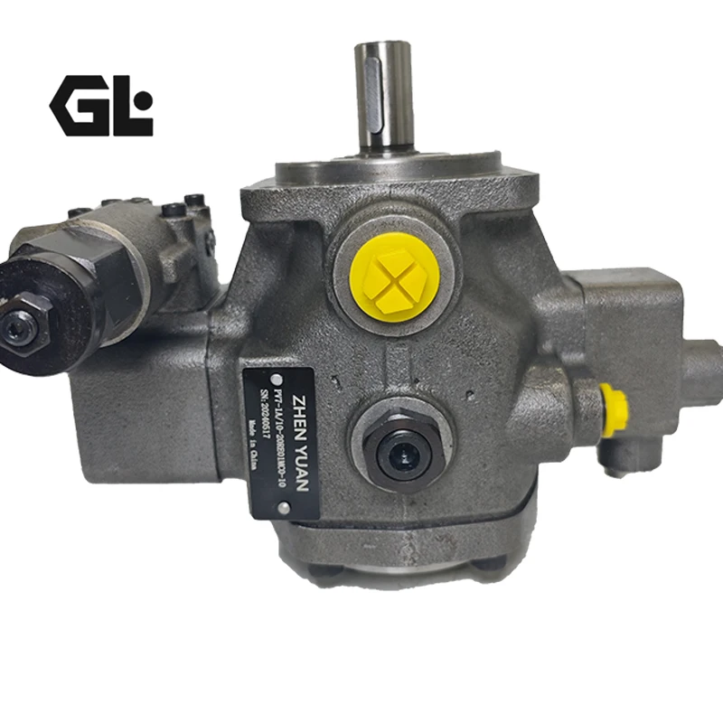
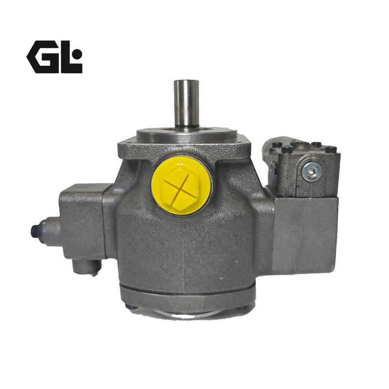

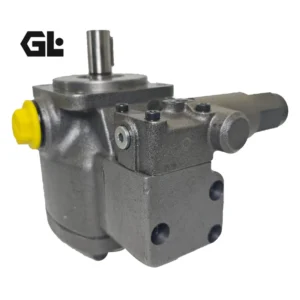
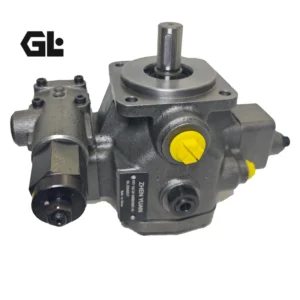


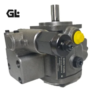
Original PV7-11 PV7 series PV7-11/6-14RA01MA0-07 power steering transfer vane pump and pump parts


Features
▶▶ Variable displacement
▶▶ Low operating noise
▶▶ Extended bearing life cycle thanks to hydrodynamically
lubricated plain bearings
▶▶ Pressure and flow can be controlled
▶▶ Low hysteresis
▶▶ Very low control up times and down control times
▶▶ Mounting dimensions according to ISO 3019-2.
▶▶ Connection dimensions according to ISO 6162-1 and
ISO 228-1
▶▶ Suitable for HLP, HETG, HEES and HFD-U hydraulic
fluids
▶▶ Standard Series PV7 single pumps can be combined
with multiple pumps as well as internal gear, external
gear, axial piston and radial piston pumps.
▶▶ Used for drives in continuous operation with variable
flow requirement and a high share in the pressure
holding function, e.g.:
–– machine tools
–– hydrostatic bearings
–– constant pressure systems
Model Analysis
PV7: Series code, indicating that this product belongs to the pilot-operated variable vane pump series
11: Structure and control type coding, used to distinguish different control structure designs within the same series, to adapt to specific control logic and installation layout requirements
The frame size parameters of the pump determine the core physical specifications such as the foundation installation dimensions and shell size of the pump, and are the key parameters for matching the installation station
14: Disposition-related adaptation parameters are associated with the basic flow output range during pump operation, indirectly affecting the power supply capacity of the hydraulic system
RA01: Control mode and pilot structure code, indicating the pilot control type of the pump and the structural specifications of key components such as internal valve cores, ensuring the accuracy of control actions
MA0: Installation and interface specification code, clearly indicating the connection method of the pump, oil port layout, etc., to ensure compatibility with the hydraulic system pipeline and base
07: Detailed specifications and adaptation numbers are used to distinguish minor configuration differences under the same basic parameters, facilitating fine-tuning requirements for adapting to different working conditions and traceability of spare parts
Core attribute
The type is pilot-operated variable vane pump, with cast steel as the main material to ensure the structural strength of the pump body under high-pressure working conditions.
The working pressure can reach up to 100bar, and it is suitable for a working temperature range of -20 ℃ to 80℃ (with slight differences depending on the sealing material). It is compatible with various hydraulic oils such as HLP and HETG.
It features low operating noise and a long service life. The installation dimensions comply with relevant industry standards and can be used in combination with various types of pumps.
Function and Role
Core functions: It can achieve variable displacement adjustment, quickly adjust the output flow through the pilot control structure, and has the ability of self-adaptive pressure regulation. Under some working conditions, it can also achieve pressure holding function. It also features short control time and low lag, enabling a rapid response to changes in system flow and pressure requirements.
Main function: Provide a stable and adjustable hydraulic power source for the hydraulic system, and control the action speed and output force of the hydraulic actuator. During the system pressure-holding stage, the displacement can be adjusted to reduce energy consumption, adapt to the power requirements of different working conditions of the hydraulic system, and ensure the efficient and stable operation of the entire hydraulic system.
Working principle
When the motor drives the rotor of the pump to rotate, the blades in the rotor slots are tightly attached to the inner surface of the stator under the action of centrifugal force and the pressure oil at the blade root. The special structure of the stator and rotor forms a sealed working chamber. During the rotation of the rotor, the volume of the sealed chamber alternately changes: when the volume increases, a negative pressure is formed to draw in hydraulic oil. When the volume shrinks, pressurize the hydraulic oil and then discharge it. By receiving the pressure or flow signals from the system through the pilot structure, the relative positions of the stator and rotor are adjusted, thereby changing the volume variation range of the sealed cavity, achieving stepless regulation of the displacement and output flow, and ultimately adapting to the dynamic requirements of the hydraulic system.
Installation Precautions
When installing, it is necessary to ensure that the coaxiality between the pump shaft and the motor is less than 0.1mm. It is recommended to use an elastic coupling to avoid abnormal operation or component wear caused by excessive coaxiality deviation.
The diameter of the suction pipe must not be less than the pump inlet specification, and the length of the oil pipe should be controlled within 1.5 meters. The connection points of the pipelines must be tightly sealed to prevent air leakage and cavitation problems.
The oil distribution plate and the stator need to be precisely positioned with locating pins. Components such as blades and rotors must not be installed in reverse. Before installation, all working surfaces should be cleaned to prevent impurities from entering the pump body and causing wear.
Before starting, loosen the exhaust screw of the pump body, jog the motor to exhaust until there are no bubbles in the oil coming out. Then, run it no-load for 5 to 10 minutes. When the oil temperature rises above 30℃, load it again for operation.
Application scenarios and models used
Application scenarios: Widely used in machine tool processing, injection molding and die-casting, construction machinery operations, automated production lines, ship deck machinery and other scenarios, especially suitable for hydraulic systems that require continuous operation, variable flow and pressure holding functions, and can adapt to various environments such as industrial workshops and outdoor construction sites.
The types of equipment used: Commonly found in CNC machining centers, grinders, injection molding machines, die-casting machines, excavators, cranes, hydraulic supports, ship steering gears, hydraulic winches and other devices that rely on hydraulic power.
A complete list of PV7 series models
This series is rich in models, covering different frame sizes, displacements and control specifications. The following are some common complete models:
PV7 – 1X/06 – 10RA01KA0 – 05
PV7 – 1X/06 – 10RA01MA0 – 10
PV7 – 1X/06 – 14RA01MA0 – 04
PV7 – 1X/06 – 14RA01MA0 – 07 – A399
PV7 – 1X/10 – 14RE01MC0 – 16
PV7 – 1X/10 – 14RE01MC5 – 16
PV7 – 1X/10 – 20RE01MC0 – 10
PV7 – 1X/16 – 20RE01MC0 – 16
PV7 – 1X/16 – 30RE01MC0 – 08
PV7 – 1X/25 – 30RE01MC3 – 16
PV7 – 1X/25 – 45RE01MC0 – 08
PV7 – 1X/100 – 118RE07MC0 – 16
PV7 – 17/10 – 14RE01MC0 – 16
PV7 – 17/10 – 20RE01MC0 – 10
PV7 – 20/20 – 25RA01MA0 – 10