


PVH141R13AF30A230000002001AB010A Vickers Eaton Axial Piston Pump 141cc 250bar
| Model Number | PVH131R13AF70B252000002001000102-466743 |
|---|
SKU
N/A
Categories Hydraulic Pump, Piston Pump
Tags air pump, axial piston pump, cnp pump, gas pump, hydraulic piston pump, jet pump, ksb pump, lpg pump, mud pump, oil pump, pcp pump, pneumatic piston pump, radial piston pump, yuken piston pump
Product Description
Product Overview
The PVH141R13AF30A230000002001AB010A is an Eaton Vickers PVH Series variable displacement inline axial piston pump with a geometric displacement of 141.1 cm³/rev, representing the largest frame size in the PVH series. Designed for open-circuit systems, this pump features a pressure compensator (constant pressure control) and delivers high flow output with stable pressure regulation for heavy-duty hydraulic applications.
The PVH series pump utilizes a swashplate-type axial piston design with nine pistons arranged in the cylinder block. The pistons reciprocate parallel to the axis of rotation, with displacement determined by the swashplate angle. The swashplate is mounted in a movable yoke, enabling stepless displacement adjustment from 0 to 141 cm³/r.
Manufactured to exact original specifications, this pump offers drop-in interchangeability—mounting flange, shaft, and port dimensions fully match original Vickers specifications. Every unit undergoes 100% simulated-condition bench testing covering rated pressure, peak pressure, and flow characterization.
Technical Specifications
Full Model Code: PVH141R13AF30A230000002001AB010A
Series: Eaton Vickers PVH Series
Pump Type: Variable displacement inline axial piston, open circuit
Geometric Displacement: 141.1 cm³/r (8.60 in³/r)
Rated Continuous Pressure: 250 bar (3625 psi)
Peak Pressure (Intermittent): 280 bar (4060 psi)
Pressure Compensator Setting: 230 bar (3300 psi)
Pressure Adjustment Range: 160–250 bar
Rated Speed (0.48 bar inlet): 2000 rpm
Maximum Speed (zero inlet pressure): 2500 rpm
Minimum Speed: 1200 rpm (at 127 mmHg inlet pressure)
Control Type: Pressure compensator (constant pressure), no load sensing/torque limiting
Mounting Flange: SAE C, 4-bolt
Input Shaft: 38.1 mm (1.50 in) dia., straight key, SAE C flange
Rotation: Right hand (clockwise, viewed from shaft end)
Inlet Port: SAE 2.5″ 1/2 C (flange type)
Outlet Port: SAE 1.25″ 1/2 C (flange type)
Drain Port: Bottom 0.875-14 SAE O-ring port
Shaft Seal: Fluorocarbon (FKM)
Housing Material: Cast iron, blue primer finish
Volumetric Efficiency: ≥95% (rated conditions)
Overall Efficiency: ≥91% (rated conditions)
Theoretical Flow (@2000 rpm): Approx. 272 L/min
Weight: Approx. 52 kg (dry)
Model Code Breakdown: PVH = variable inline piston pump (open circuit); 141 = nominal displacement 141 cm³/r; R = right hand rotation; 13 = control type & design code (pressure compensator, standard design); A = mounting flange (SAE C, 4-bolt); F30 = input shaft specification (1.50 in dia., 2.44 in length, straight key); A = standard housing, no integral relief valve; 23 = pressure compensator setting 230 bar; 0000 = no additional controls; 2001 = design version & performance level; AB010A = seal, paint & detail configuration.
Key Technical Advantages
1. High Volumetric Efficiency Piston-Cylinder Fit
The cylinder block is constructed from high-strength alloy steel, with nine pistons precision-lapped to micron-level clearance with cylinder bores. At 250 bar continuous pressure and 2000 rpm rated speed, volumetric efficiency reaches 95% or higher, with overall efficiency exceeding 91%. The cylinder block-valve plate friction pair is optimized for both sealing performance and wear life.
2. Pressure Compensator Constant Pressure Control
This model features a single “A” type pressure compensator. When system pressure reaches the set value (factory 230 bar), the compensator automatically drives the swashplate back, reducing displacement to maintain constant system pressure—preventing overload and energy waste. The pressure adjustment range is 160–250 bar, allowing flexible tuning to system requirements. On startup, the swashplate automatically returns to zero, enabling zero-pressure start with reduced starting torque shock.
3. Heavy-Duty Bearings and Swashplate Support Structure
The input shaft is supported by heavy-duty bearings capable of handling combined radial and axial loads. The swashplate is mounted in a movable yoke supported by pivots, providing low friction and fast response during displacement changes. L10 bearing life meets long-duration continuous operation requirements. The pump design accommodates through-drive configurations for tandem-mounted auxiliary pumps.
4. Standardized Interfaces and Maintenance Accessibility
The pump features standard SAE port configurations: SAE C 4-bolt mounting flange, SAE flange-type inlet and outlet ports, and SAE O-ring drain port. All interface dimensions match original Vickers specifications exactly, enabling direct replacement without piping modification. The rotating group utilizes a modular design, with critical components replaceable through rotating group kits.
Application Areas
Large Hydraulic Presses & Forging Equipment: High-flow constant-pressure power source for actuators
Metallurgical & Mining Equipment: Sustained high-pressure oil supply for heavy-load conditions
Injection Molding Machines: High-flow hydraulic power unit for clamp and injection circuits
Construction Machinery: Main hydraulic pump for large excavators and cranes
Heavy Machine Tools: Primary oil supply pump for hydraulic power stations
Marine Hydraulic Systems: Deck machinery and steering gear hydraulic power source
Expert Maintenance Tips
Pre-Installation Check: Verify shaft-to-drive alignment within 0.05 mm tolerance. Use flexible couplings to compensate for minor angular misalignment. Tighten SAE C 4-bolt flange bolts in diagonal sequence to specified torque. Confirm suction line diameter meets pump inlet flow requirements to avoid excessive suction resistance.
First Start-Up: Fill the pump housing with clean hydraulic fluid to the overflow port level before starting—dry running is strictly prohibited. Run at no-load for 5–10 minutes during initial start-up, checking suction line sealing and case drain line flow. Displacement adjustment must be performed at full displacement and low operating pressure.
Pressure Compensator Adjustment: Factory pressure compensator setting is 230 bar. To adjust, turn the adjustment screw counterclockwise to increase setting pressure, clockwise to decrease. Use a pressure gauge to monitor system pressure during adjustment. Adjustment increments should not exceed 10 bar per step, with stability verification after each adjustment.
Hydraulic Fluid Maintenance: ISO VG32/46/68 anti-wear hydraulic fluid is recommended, with cleanliness level not lower than ISO 4406 18/16/13. Normal operating temperature range: -20°C to +80°C. Check fluid cleanliness every 500 hours; replace filter elements when differential pressure exceeds 3 bar. Inlet pressure should be maintained within 0.07–0.48 bar (absolute) to prevent cavitation.
Storage Requirements: During storage, the pump interior should remain filled with rust-preventive oil, with all ports sealed. Storage temperature range: -20°C to +60°C, avoiding direct sunlight and humid environments. After 12 months of storage, re-bench testing is recommended.


Company Profile

Frequently Asked Questions
1.What ls our Main Products?
1.Hydraulic pump
2.Hydraulic valve
3.Hydraulic motor
4.Hydraulic cylinder
5.Hydraulic parts
2. What about the MOQ?
3.What are your advantages?
- Adhere to quality first.
- Support customization, ODM & OEM service.
- 1-year warranty and complete after-sales support.
- Safe and fast shipping worldwide.
- 24-hour online service for your inquiries.
4.Are you a manufacturer? What’s your delivery time?
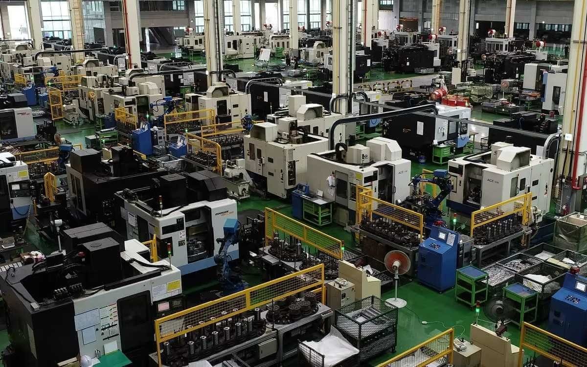
Yes, we are a manufacturer with our own factory.
Common models are in stock, and orders are usually shipped within 1–3 days.
5.Which payment methods are accepted?
We accept T/T, L/C, PayPal, VISA, Western Union, Apple Pay, Google Pay, Afterpay (Clearpay), Klarna, and Trade Assurance.
For full orders: 30% deposit, balance before shipment.
For small/sample orders: full payment in advance.
6.How will you deliver my goods?
We offer flexible shipping options: DHL, UPS, FedEx, TNT, EMS, as well as air or sea freight.
All deliveries ensure door-to-door fast and safe service.
7.How do you inspect and guarantee your products?
All products are tested before shipment to ensure perfect working condition.
We offer a 12-month warranty — if a product fails due to quality issues, we provide free spare parts or repair support.
8.What about after-sales service?
If you encounter any problem during use, please contact your sales manager or our support team at any time.
We will respond quickly and help solve the issue efficiently.
9.What are your main applications?
- Hydraulic systems
- Agricultural machinery
- Construction machinery
- Automobile industry
- Local distributors and maintenance centers
10.Can I get a discount for bulk orders?
Yes. We offer competitive wholesale prices and try our best to give benefits to long-term partners.
Shoot Us An Email
Professional Manufacturer