
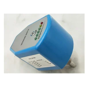
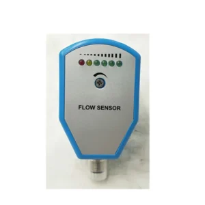

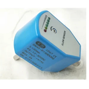

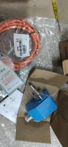
Product Overview
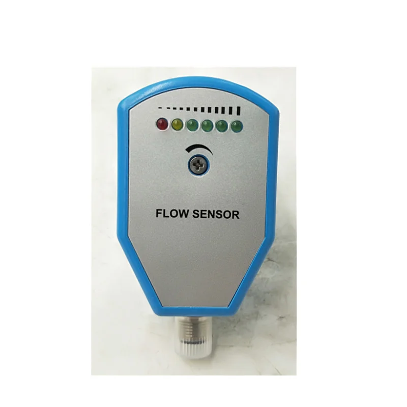
The SN45 / SN50 / SN55 series are thermal dispersion electronic flow sensor switches — the core sensing elements for pipeline flow velocity monitoring, flow-loss alarm, and pump dry-run protection in industrial hydraulic and fluid control systems. The SN45 represents the classic generation (with select models upgraded to the FS110 series), the SN55 is the current mainstream production model, and the SN50 serves as an intermediate specification. All three share a unified thermal sensing platform with consistent core performance parameters, differing only in thread interface, output configuration, and probe length combinations.
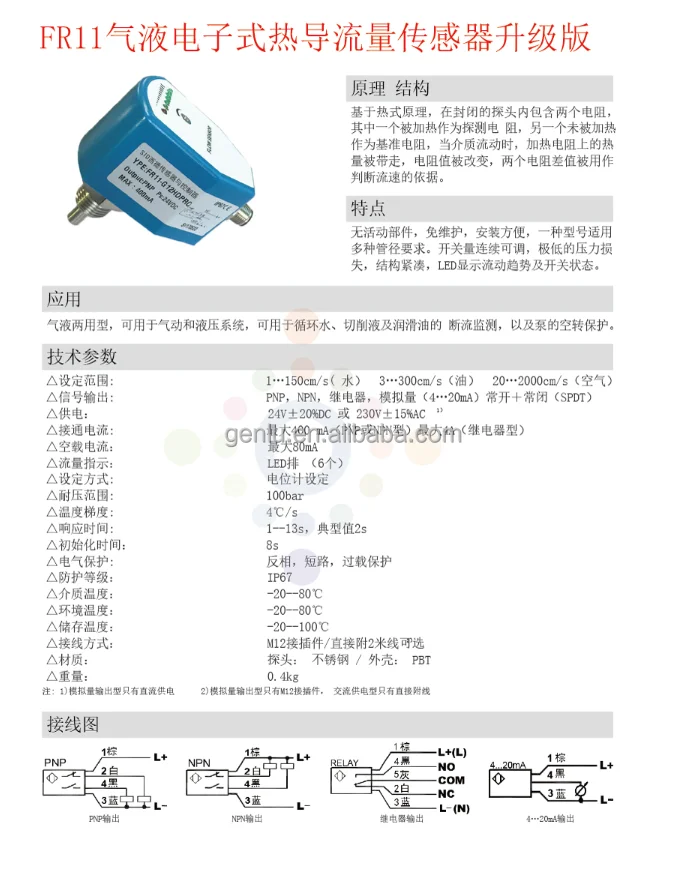
These products operate on the thermal dispersion principle: the sealed probe houses two precision resistive elements — one continuously heated as the sensing resistor and one unheated as the reference resistor. When fluid flows past the probe, it carries heat away from the heated element, altering its resistance value. The circuit continuously monitors the temperature differential between the two resistors and converts it into a flow velocity determination. When flow reaches or drops below the user-set threshold, a switching signal is output immediately.
All models feature gas-liquid dual-use capability, detecting water, hydraulic oil, cutting fluid, lubricating oil, and compressed air. The entire series undergoes 100% factory functional testing, guaranteeing drop-in interchangeability with existing systems — ready to install and operate out of the box.
Technical Specifications (Bulleted List)
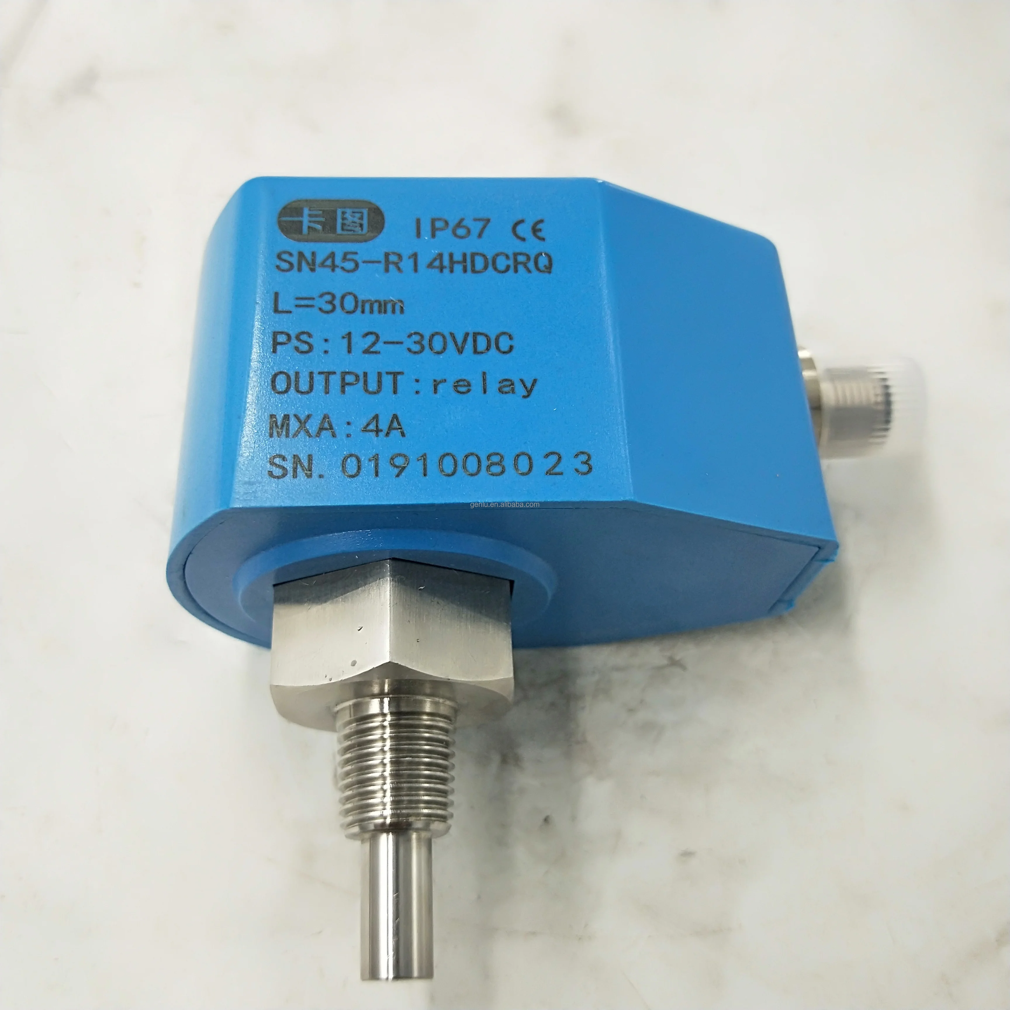
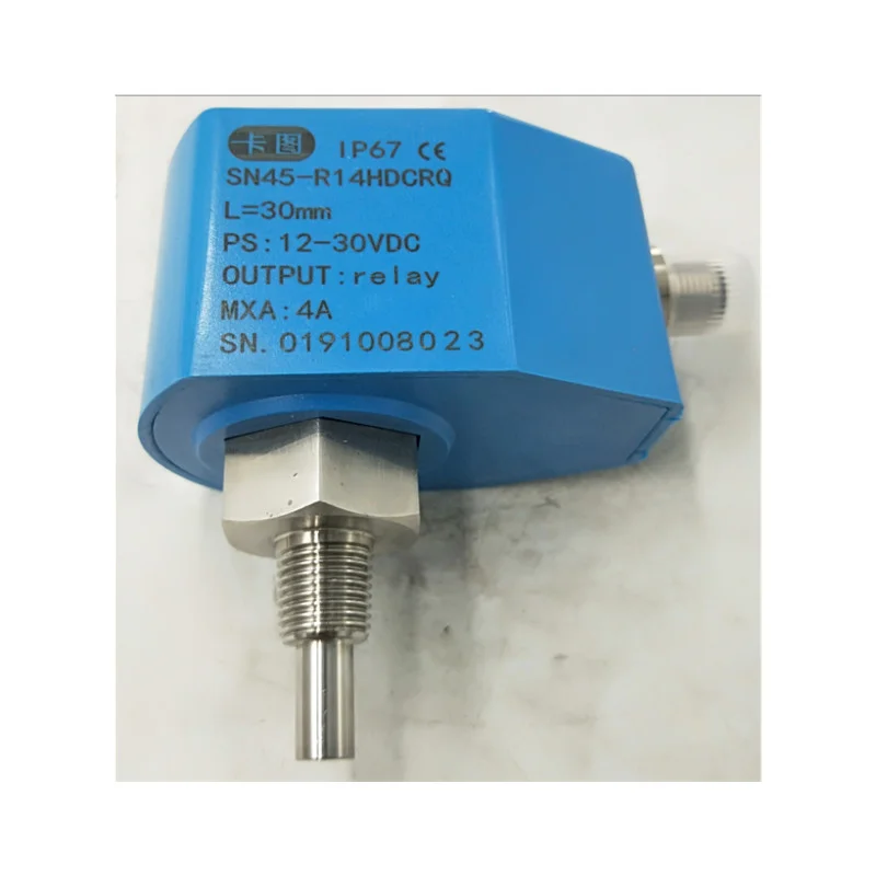
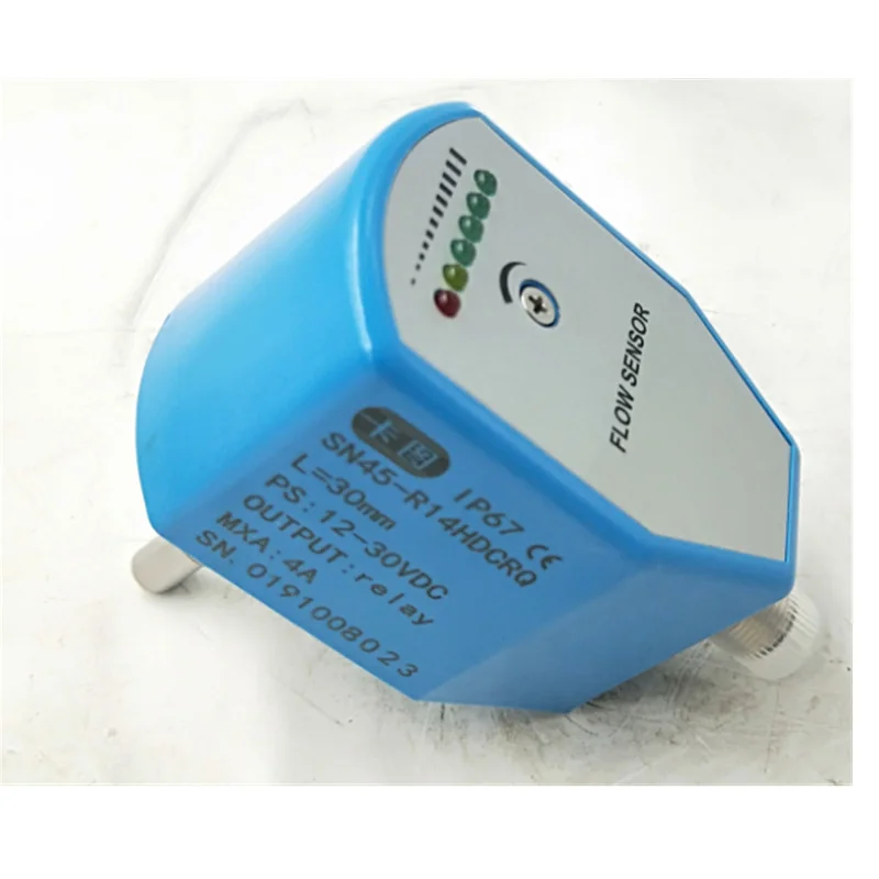
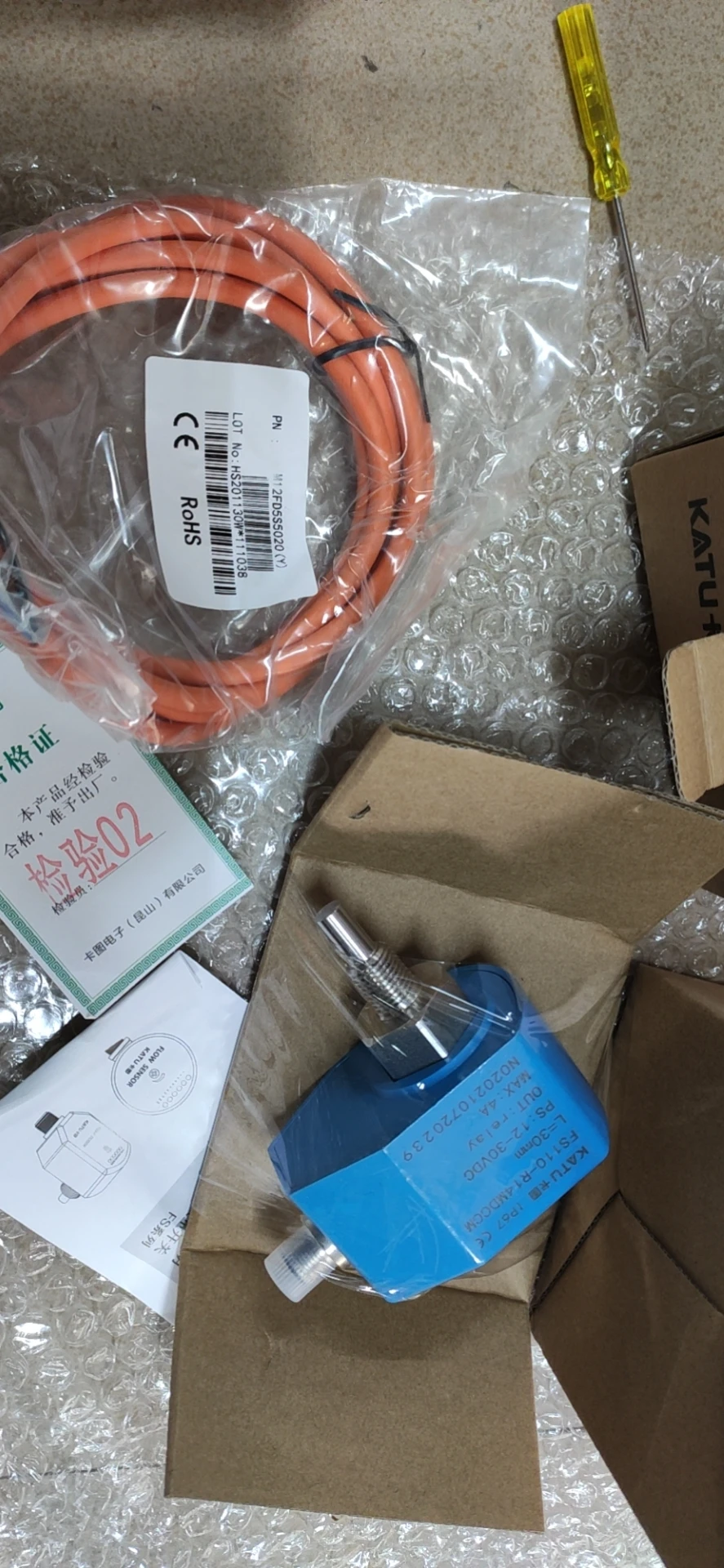
SN45-R14HDCRQ (Upgraded Model: FSK6-FS110-R14MDCCM)
- Product Series: SN45 (Classic, upgraded to FS110 series)
- Operating Principle: Thermal Dispersion
- Thread Connection: R1/2 (PT1/2 NPT taper external thread)
- Power Supply: DC 24V ±20%
- Output Type: PNP transistor output
- Contact Configuration: Relay SPDT (NO + NC)
- Wiring: Q = Direct cable (standard 2 m pigtail)
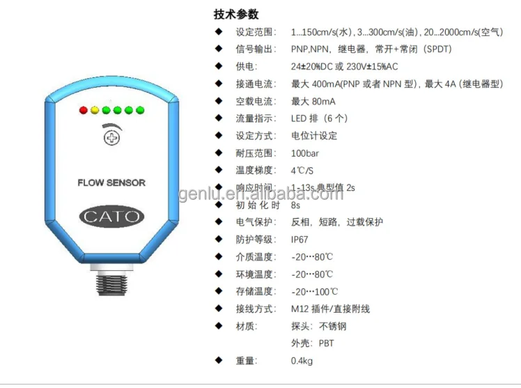
- Flow Setting Range (Water): 1–150 cm/s
- Flow Setting Range (Oil): 3–300 cm/s
- Flow Setting Range (Air): 20–2000 cm/s
- Signal Output Options: PNP / NPN / Relay / Analog (4–20 mA) / NO+NC (SPDT)
- Switching Current: Max. 400 mA (PNP/NPN); Max. 4 A (Relay)
- No-Load Current: Max. 80 mA
- Flow Indication: LED array (6 LEDs)
- Setting Method: Potentiometer adjustment
- Pressure Rating: 100 bar
- Temperature Gradient: ≤4°C/s
- Response Time: 1–13 s, typical 2 s
- Initialization Time: Approx. 8 s
- Electrical Protection: Reverse polarity, short circuit, overload protection
- Ingress Protection: IP67
- Media Temperature: -20 to +80°C
- Ambient Temperature: -20 to +80°C
- Storage Temperature: -20 to +100°C
- Probe Material: Stainless steel (SUS 304/316L)
- Housing Material: PBT
- Weight: Approx. 0.4 kg
SN45-G12HDCRQ (Upgraded Model: FS110-G12MDCCM)
- Product Series: SN45 (Classic, upgraded to FS110 series)
- Operating Principle: Thermal Dispersion
- Thread Connection: G1/2 (external thread)
- Power Supply: DC 24V ±20%
- Output Type: PNP transistor output
- Contact Configuration: Relay SPDT (NO + NC)
- Wiring: Q = Direct cable (standard 2 m pigtail)
- Flow Setting Range (Water): 1–150 cm/s
- Flow Setting Range (Oil): 3–300 cm/s
- Flow Setting Range (Air): 20–2000 cm/s
- Pressure Rating: 100 bar
- Temperature Gradient: ≤4°C/s
- Response Time: 1–13 s, typical 2 s
- Initialization Time: Approx. 8 s
- Electrical Protection: Reverse polarity, short circuit, overload protection
- Ingress Protection: IP67
- Media Temperature: -20 to +80°C
- Ambient Temperature: -20 to +80°C
- Storage Temperature: -20 to +100°C
- Probe Material: Stainless steel
- Housing Material: PBT
- Weight: Approx. 0.4 kg
SN55-G12HDCRQ (Current Mainstream Model)
- Product Series: SN55 (Current mainstream production model)
- Operating Principle: Thermal Dispersion
- Thread Connection: G1/2 (external thread)
- Power Supply: DC 24V ±20%
- Output Type: PNP transistor output
- Contact Configuration: Relay SPDT (NO + NC)
- Wiring: Q = Direct cable (standard 2 m pigtail)
- Flow Setting Range (Water): 1–150 cm/s
- Flow Setting Range (Oil): 3–300 cm/s
- Flow Setting Range (Air): 20–2000 cm/s
- Signal Output Options: PNP / NPN / Relay / Analog (4–20 mA) / NO+NC (SPDT)
- Switching Current: Max. 400 mA (PNP/NPN); Max. 4 A (Relay)
- No-Load Current: Max. 80 mA
- Flow Indication: LED array (6 LEDs)
- Setting Method: Potentiometer adjustment
- Pressure Rating: 100 bar
- Temperature Gradient: ≤4°C/s
- Response Time: 1–13 s, typical 2 s
- Initialization Time: Approx. 8 s
- Electrical Protection: Reverse polarity, short circuit, overload protection
- Ingress Protection: IP67
- Media Temperature: -20 to +80°C
- Ambient Temperature: -20 to +80°C
- Storage Temperature: -20 to +100°C
- Wiring Options: M12 connector / Direct cable (standard 2 m pigtail)
- Probe Material: Stainless steel
- Housing Material: Stainless steel / PBT
- Weight: Approx. 0.4 kg
SN55 Series Model Code Decoding
- SN55: Product series designation (Electronic flow sensor switch)
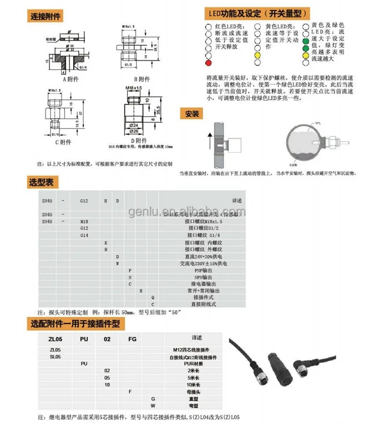
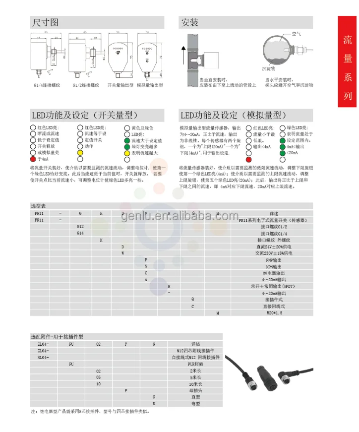
- Thread Interface: M18K = M18×1.5 internal thread / G12H = G1/2 external thread / G14H = G1/4 external thread
- Power Supply: H = DC 24V ±20%
- Output Type: P = PNP / N = NPN / C = Relay / R = NO+NC (SPDT)
- Wiring Method: C = M12 connector / Q = Direct cable (standard 2 m pigtail)
- Probe Length: Trailing numeric value in mm, default 30 mm
Key Technical Advantages
1. Thermal Dispersion — Zero Moving Parts Design
The entire SN45/SN50/SN55 series employs thermal dispersion detection technology with absolutely no mechanical moving parts inside the probe. Compared to traditional paddle-type or piston-type flow switches, this design fundamentally eliminates the risk of jamming caused by particulates, oil sludge, or scale deposits in the media. Zero wear, zero fatigue — truly maintenance-free operation with service life far exceeding mechanical alternatives.
The entire SN45/SN50/SN55 series employs thermal dispersion detection technology with absolutely no mechanical moving parts inside the probe. Compared to traditional paddle-type or piston-type flow switches, this design fundamentally eliminates the risk of jamming caused by particulates, oil sludge, or scale deposits in the media. Zero wear, zero fatigue — truly maintenance-free operation with service life far exceeding mechanical alternatives.
2. Gas-Liquid Dual-Use — One Model, Multiple Pipe Sizes
A single model covers flow velocity detection across three media types: water (1–150 cm/s), oil (3–300 cm/s), and air (20–2000 cm/s) — no sensor swap required when changing media. One model accommodates multiple pipe diameters, dramatically simplifying spare parts management and procurement inventory while reducing total cost of ownership.
A single model covers flow velocity detection across three media types: water (1–150 cm/s), oil (3–300 cm/s), and air (20–2000 cm/s) — no sensor swap required when changing media. One model accommodates multiple pipe diameters, dramatically simplifying spare parts management and procurement inventory while reducing total cost of ownership.
3. 100 bar Pressure Rating · IP67 Full-Seal Protection
The entire series is rated for 100 bar (10 MPa) operating pressure, allowing direct installation in high-pressure hydraulic circuits without additional pressure-reducing devices. The IP67 ingress protection rating ensures reliable long-term operation in harsh industrial environments with moisture, dust, and water splash. The housing is manufactured from PBT engineering plastic or stainless steel, with SUS stainless steel probes providing excellent corrosion resistance.
The entire series is rated for 100 bar (10 MPa) operating pressure, allowing direct installation in high-pressure hydraulic circuits without additional pressure-reducing devices. The IP67 ingress protection rating ensures reliable long-term operation in harsh industrial environments with moisture, dust, and water splash. The housing is manufactured from PBT engineering plastic or stainless steel, with SUS stainless steel probes providing excellent corrosion resistance.
4. 6-Stage LED Real-Time Flow Trend Display
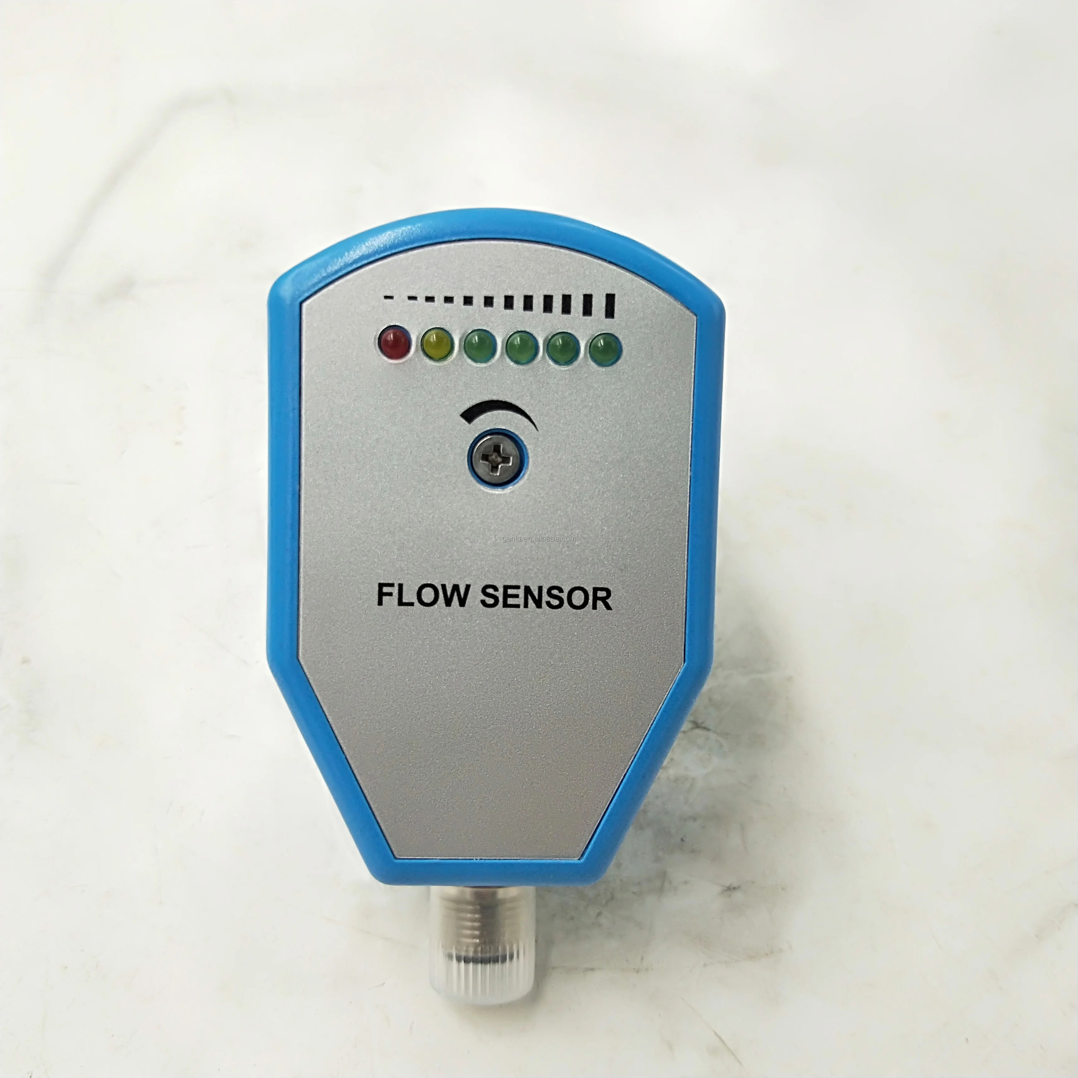
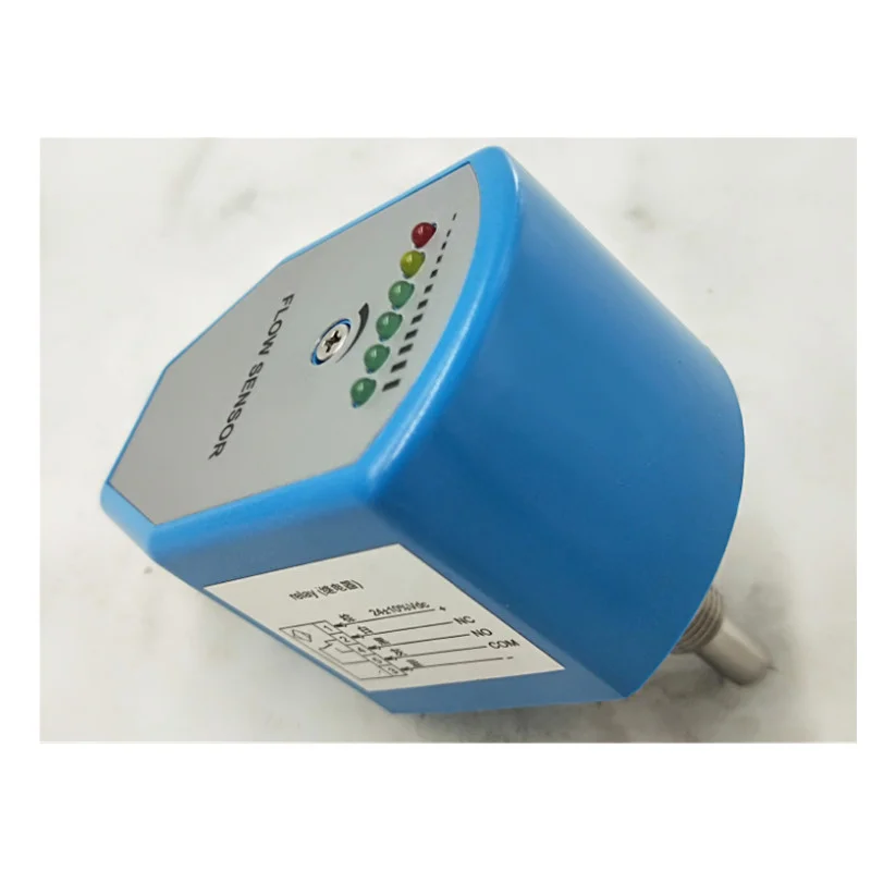
Equipped with 6 high-brightness LED indicators providing intuitive flow trend and switching status visualization: Red LED indicates flow loss or velocity below setpoint; Yellow LED indicates velocity at setpoint with switch actuation; Green LEDs illuminate progressively as velocity exceeds setpoint — more green LEDs = higher flow rate. On-site maintenance personnel can assess system status at a glance without instruments.
Equipped with 6 high-brightness LED indicators providing intuitive flow trend and switching status visualization: Red LED indicates flow loss or velocity below setpoint; Yellow LED indicates velocity at setpoint with switch actuation; Green LEDs illuminate progressively as velocity exceeds setpoint — more green LEDs = higher flow rate. On-site maintenance personnel can assess system status at a glance without instruments.
5. Multiple Output Signal Formats · Flexible Integration
Supports PNP, NPN, relay (SPDT NO+NC), and analog (4–20 mA) output configurations, enabling seamless interface with PLCs, DCS, relay modules, alarm beacons/buzzers, and other industrial control devices — no additional signal conversion modules required. The relay output supports up to 4 A switching current, capable of directly driving small solenoid valves or alarm devices.
Supports PNP, NPN, relay (SPDT NO+NC), and analog (4–20 mA) output configurations, enabling seamless interface with PLCs, DCS, relay modules, alarm beacons/buzzers, and other industrial control devices — no additional signal conversion modules required. The relay output supports up to 4 A switching current, capable of directly driving small solenoid valves or alarm devices.
6. Ultra-Fast Response · Precision Protection
Typical response time of just 2 seconds (adjustable range 1–13 s) with approximately 8 s initialization time. In emergency scenarios such as cooling water loss or lubricating oil interruption, the switch triggers an interlock shutdown signal within seconds, effectively protecting pumps, hydraulic power units, and compressors from dry-run damage — preventing catastrophic equipment failure and costly repairs.
Typical response time of just 2 seconds (adjustable range 1–13 s) with approximately 8 s initialization time. In emergency scenarios such as cooling water loss or lubricating oil interruption, the switch triggers an interlock shutdown signal within seconds, effectively protecting pumps, hydraulic power units, and compressors from dry-run damage — preventing catastrophic equipment failure and costly repairs.
Application Areas
- Hydraulic Power Unit Cooling Circuits: Monitor cooling water/oil circulation flow; interlock shutdown when flow drops below setpoint, preventing hydraulic oil overheating, seal degradation, and system failure
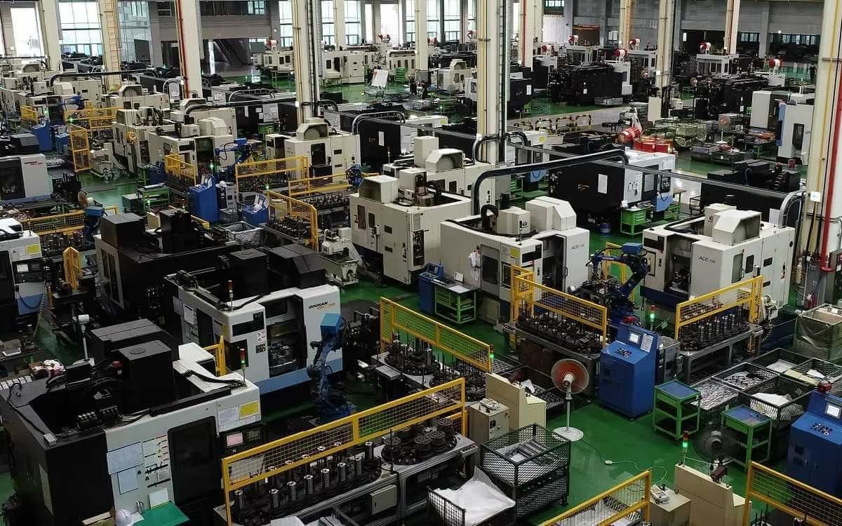
- CNC Machine Tool Spindle Cooling: Monitor cutting fluid and spindle coolant flow status; immediate alarm and spindle stoppage upon flow loss to prevent spindle bearing overheating
- Water Pump / Hydraulic Pump Dry-Run Protection: Installed at pump suction or discharge piping; immediately cuts pump motor power upon flow loss due to blockage, valve mis-closure, or low tank level
- Centralized Lubrication Systems: Installed downstream of lubrication distributors to verify adequate oil delivery to each lubrication point
- Compressed Air Pipeline Monitoring: Detect air supply loss in pneumatic systems caused by pipe rupture or fitting disconnection
- Injection Molding Machine Mold Temperature Control: Monitor mold cooling channel flow to maintain mold temperature within process window, preventing product sink marks and warpage
- Laser Cutting Equipment Cooling: Protect laser optical components from thermal damage by monitoring cooling water flow
- Chemical & Pharmaceutical Processing: Reactor jacket cooling water monitoring and clean fluid flow interlock protection
Expert Maintenance Tips
- Installation Location Selection: Install on a straight pipe section away from elbows, valves, pump outlets, and other flow disturbance sources. Upstream straight run should be no less than 10× pipe diameter; downstream straight run no less than 5× pipe diameter to ensure stable flow profile and accurate measurement.
- Installation Orientation: When mounting on vertical piping, install only on sections with upward flow — never mount with the probe pointing downward, as trapped air bubbles will compromise detection accuracy. On horizontal piping, orient the probe upward or sideways, avoiding the pipe bottom where air pockets and sediment accumulate.
- Initial Setting Calibration: After first power-up, allow approximately 8 seconds for initialization to complete. With media flowing at the minimum velocity to be monitored, adjust the potentiometer until the first yellow LED just illuminates — this is your setpoint. Always perform calibration under actual operating conditions, never in static state.
- Seal & Connection Inspection: After each removal and reinstallation, inspect the probe O-ring for damage, deformation, or aging — replace immediately if compromised. R1/2 taper thread connections require appropriate sealing tape or liquid sealant; G1/2 external thread connections must verify gasket integrity. Do not over-torque during installation to avoid probe damage.
- Periodic Probe Cleaning: Although the thermal probe is maintenance-free with no moving parts, long-term operation may result in scale, oil film, or media deposits on the probe surface, degrading thermal transfer efficiency. Recommended cleaning interval: every 6–12 months. Remove the probe and gently wipe with a soft cloth or neutral cleaner. Never use abrasive tools that could scratch the stainless steel probe surface.
- Media Compatibility Verification: Standard stainless steel probes are suitable for water, mineral oils, emulsions, and compressed air. For strong acids, strong alkalis, or high-chloride media, confirm whether 316L stainless steel probes or special anti-corrosion coating versions are required for your application.