
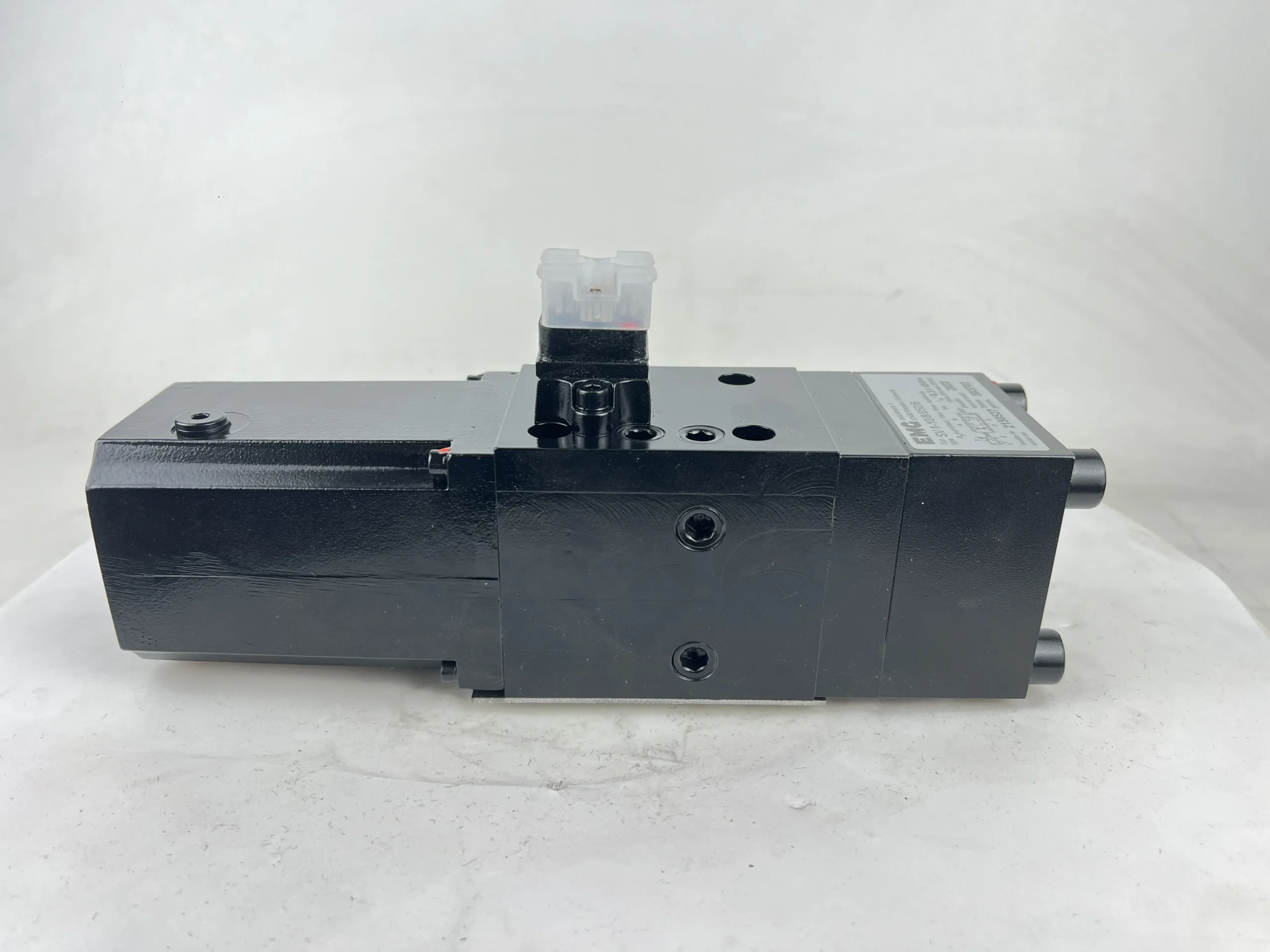
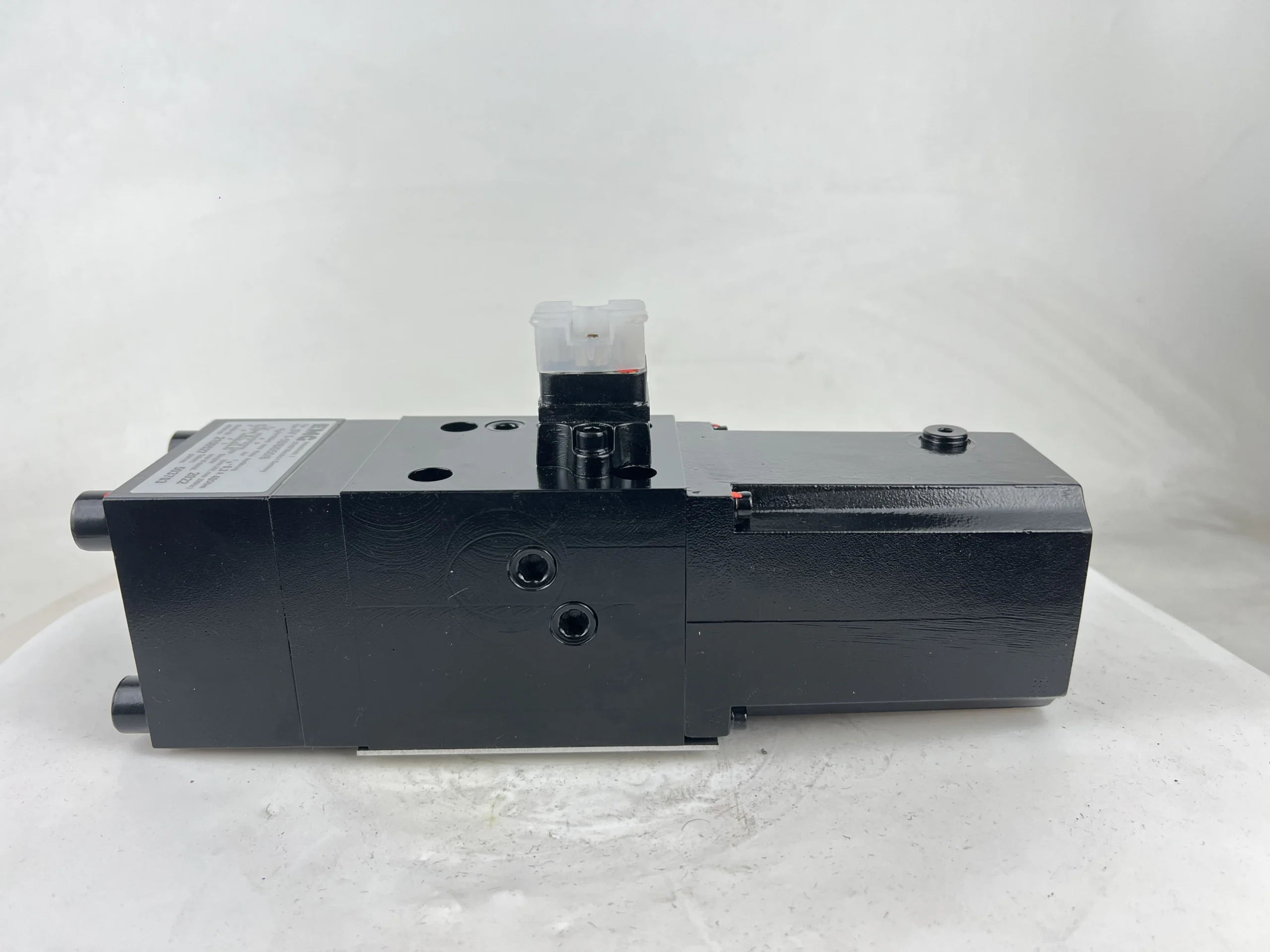



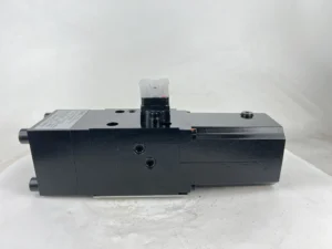
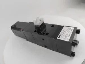
Product Overview
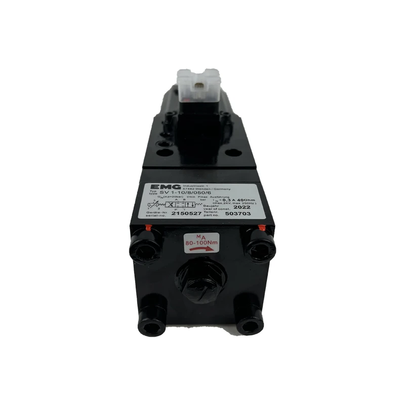
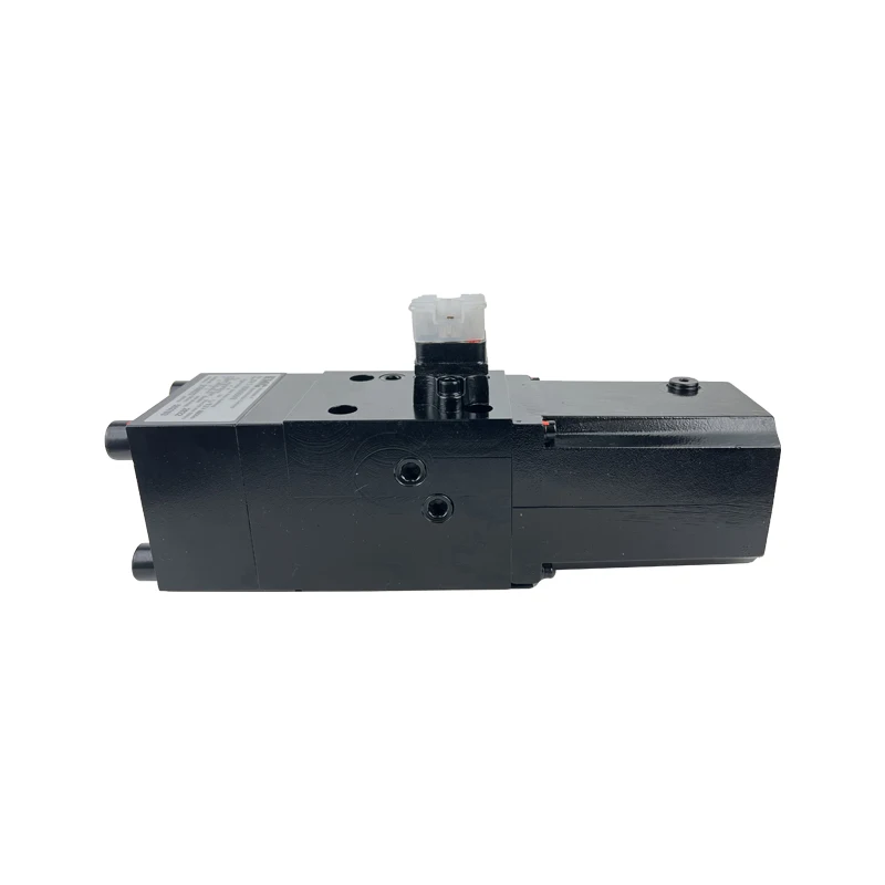
The SV 1-10 series is a single-stage, 4/3-way proportional directional servo valve engineered and manufactured by EMG Automation GmbH, Germany. The series comprises three core flow variants — SV1-10/16/315/6, SV1-10/32/315/6, and SV1-10/48/315/6 — designed to the DIN 24340 / ISO 4401 NG10 (Cetop 5) standard. The valve converts an electrical input signal into a proportional hydraulic flow output through an electro-magnetic rotary drive with patented return springs, maintaining a constant pressure drop across the internal control edges.
As a drop-in replacement for the original EMG SV 1-10, all three variants are fully compatible in mounting interface, electrical connection, and performance characteristics with the OEM specification — no modification to the manifold block or control circuitry is required. Every unit undergoes 100% simulation-based testing prior to shipment, covering null stability, flow linearity, step response, and internal leakage.
The three variants share an identical single-stage valve body architecture, electro-magnetic rotary drive mechanism, and NG10 mounting interface. The key differentiator is rated flow capacity: at ΔpN = 20 bar, the SV1-10/16/315/6 delivers 16 L/min, the SV1-10/32/315/6 delivers 32 L/min, and the SV1-10/48/315/6 delivers 48 L/min. Users select the appropriate variant based on system flow requirements.
Technical Specifications
All parameters below are verified against the EMG official SV 1-10 technical datasheet (DB_SV1-10_05_en) and corroborated by authorized supplier technical pages:
Common Specifications (All Three Variants):
Product Series: EMG SV 1-10 (single-stage proportional servo valve)
Spool Function: 4/3-way proportional directional valve
Standard Size: NG10 (DIN 24340) / Cetop 5 / ISO 4401
Max Operating Pressure: 315 bar (operating range 30–315 bar)
Max Permissible Return Pressure: 30 bar
Drive Type: Electro-magnetic rotary drive with return springs (patented)
Control Signal: ±10 V DC or 4–20 mA (optional)
Hysteresis: < 2.5%
Operating Temperature Range: -20 °C to +80 °C
Dimensions (H×W×L): 127 × 72 × 264 (325) mm
Hydraulic Fluid: Mineral oil (ISO VG 46 recommended); HFC and HFD available
Overlap: 1% or 6% (per type code suffix)
SV1-10/16/315/6 Specific Parameters:
Rated Flow (ΔpN = 20 bar): 16 L/min
Rated Flow (ΔpN = 70 bar): 24 L/min
Spool Size: 10 mm
Coil Resistance: 20 Ω ±10% (6-wire configuration)
Frequency Response: > 90 Hz (-3dB, 100% amplitude)
Typical Internal Leakage: 0.25 L/min (at ps = 100 bar, I = 0 mA, t = 50 °C)
Weight: Approx. 5.2 kg
SV1-10/32/315/6 Specific Parameters:
Rated Flow (ΔpN = 20 bar): 32 L/min
Rated Flow (ΔpN = 70 bar): 46 L/min
Weight: Approx. 8.5 kg
SV1-10/48/315/6 Specific Parameters:
Rated Flow (ΔpN = 20 bar): 48 L/min
Rated Flow (ΔpN = 70 bar): 70 L/min
Typical Internal Leakage: 0.7 L/min (at ps = 100 bar, I = 0 mA, t = 50 °C)
Weight: Approx. 8.5 kg
Note: Specifications are based on EMG Automation official datasheet DB_SV1-10_05_en and verified supplier technical pages. All three variants share identical valve body dimensions, mounting interfaces, and electrical connections, differing only in rated flow, weight, and certain dynamic characteristics.
Key Technical Advantages
1. Patented Electro-Magnetic Rotary Drive for High-Resolution Flow Control
All three SV 1-10 variants employ EMG’s patented electro-magnetic rotary drive mechanism. When the coil receives a modulated current signal from the drive amplifier, a proportional torque vector rotates the armature shaft through a micro-degree angle, which is mechanically coupled into linear spool displacement. This architecture eliminates the nozzle-clogging and fluid-contamination sensitivity inherent in nozzle-flapper designs while achieving dynamics that are largely independent of system pressure.
2. Temperature- and Pressure-Independent Null Stability
The series exhibits exceptional null-position stability: temperature drift of the null point is not measurable and is theoretically zero. Under cold starts, extended continuous operation, or significant ambient temperature swings, the spool does not drift due to thermal expansion or pressure fluctuation. For applications such as rolling mill gauge control (AGC) and injection molding hold-pressure phases, where null-point precision directly determines product quality, this characteristic is decisive.
3. Rotary Spool and Clearance-Adjustment Design for Online Flushing
The SV 1-10 features a rotary spool design combined with a clearance-adjustment structure that reduces sliding friction to a minimum. This design not only generates fewer wear particles but also permits online flushing without oil leakage — internal contaminants can be cleared without valve removal, significantly reducing unplanned downtime.
4. Dual Pre-Loaded Return Springs for Fail-Safe Operation
The valve is equipped with dual pre-loaded mechanical return springs. Upon loss of power supply or control signal, spring force rapidly returns the spool to the center position, isolating ports A/B from P/T and bringing the actuator to a controlled stop. This fail-safe mechanism is critical for rolling mills, presses, and large hydraulic cylinders where uncontrolled motion poses a safety risk.
5. 100% Simulation-Based Testing on Every Unit
Every SV 1-10 undergoes 100% simulation-based testing prior to shipment. Test protocols cover rated flow calibration, hysteresis and linearity measurement, step-response verification, and internal leakage detection — all performed under simulated operating pressure and temperature conditions to ensure the delivered performance curve matches the official datasheet.
Application Areas
Metal Rolling Equipment: Hydraulic gap control (AGC) for hot and cold rolling mills, roll bending systems, strip edge-position control
Continuous Casting & Galvanizing Lines: Mold level control, zinc coating thickness regulation circuits
CNC Machine Tools & Machining Centers: Precision hydraulic feed axes, fixture positioning and clamping systems
Industrial Robotics: Hydraulic drive control for heavy-payload joints, force/position hybrid control of end effectors
Injection Molding Machines: Clamping and injection phase pressure/flow compound control
Material Testing Systems: Electro-hydraulic servo fatigue test rigs, structural component loading systems
Construction Machinery: Pilot control circuits for excavators and loaders, load-sensing hydraulic systems
Expert Maintenance Tips
Pre-Installation Checks:
Verify the manifold mounting surface conforms to ISO 4401 NG10: surface roughness Ra ≤ 0.8 μm, flatness deviation ≤ 0.01 mm/100 mm
Flush all piping with clean hydraulic fluid prior to installation; ensure system cleanliness reaches ISO 4406 18/16/13 or better
Inspect O-rings for damage; tighten mounting bolts in diagonal sequence to specified torque
Operational Maintenance:
Use a 5–10 μm precision pressure filter, specified without bypass and equipped with a contamination indicator
Recommended fluid: ISO VG 46 mineral oil; maintain operating viscosity within 15–400 cSt
Periodically monitor internal leakage: typical values at ps = 100 bar, I = 0 mA, t = 50 °C are 0.25 L/min (16 variant), 0.4 L/min (32 variant), and 0.7 L/min (48 variant). Significant deviation indicates spool/sleeve wear
Leverage the rotary spool design’s online flushing capability to periodically clear accumulated particulates from the valve interior during system operation
Troubleshooting Guide:
Spool fails to actuate or responds slowly: Verify control signal reaches the coil (±10 V / 4–20 mA); measure coil resistance against rated value
Null-point drift: After ruling out fluid contamination, inspect return springs for fatigue or fracture after extended service
Abnormal noise: Check that system return pressure does not exceed the 30 bar maximum; confirm no back-pressure blockage in the return line