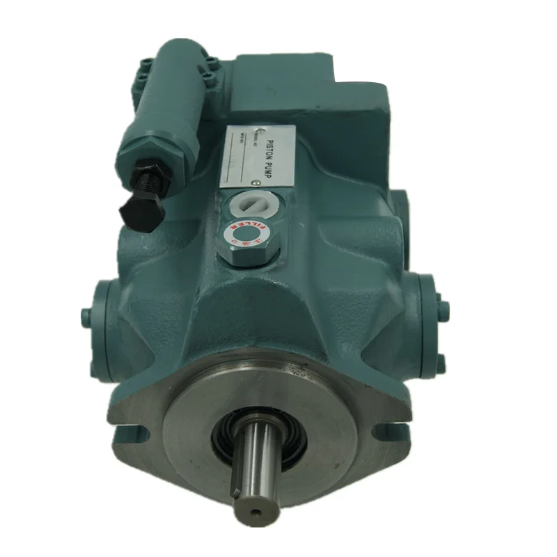
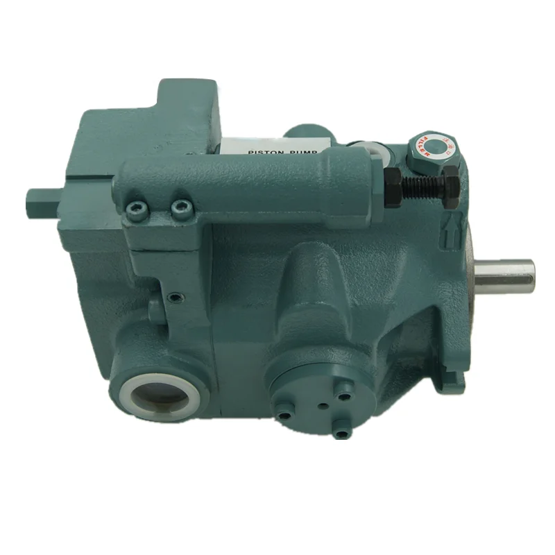
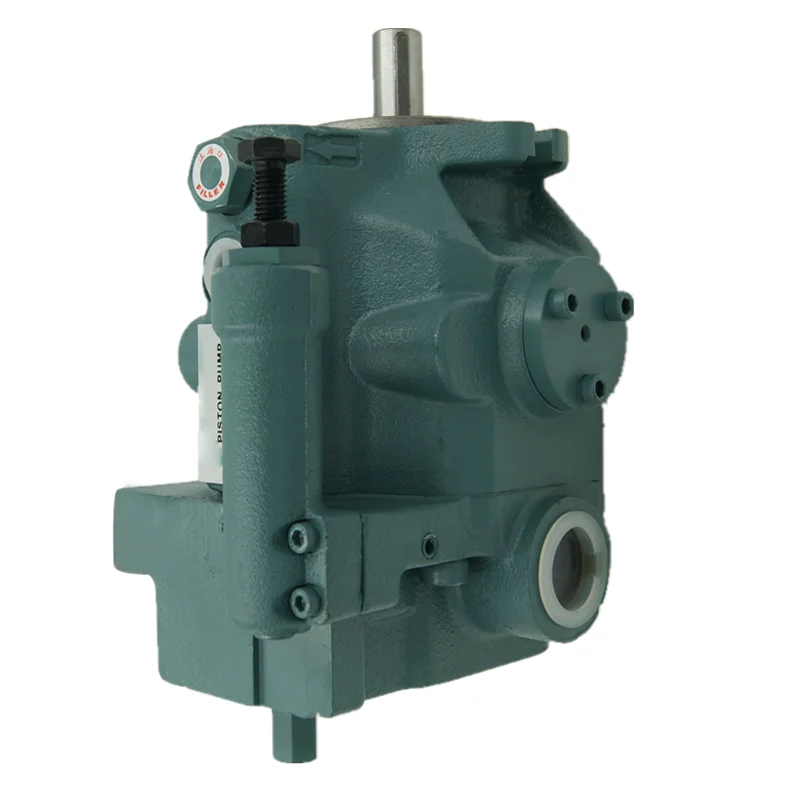
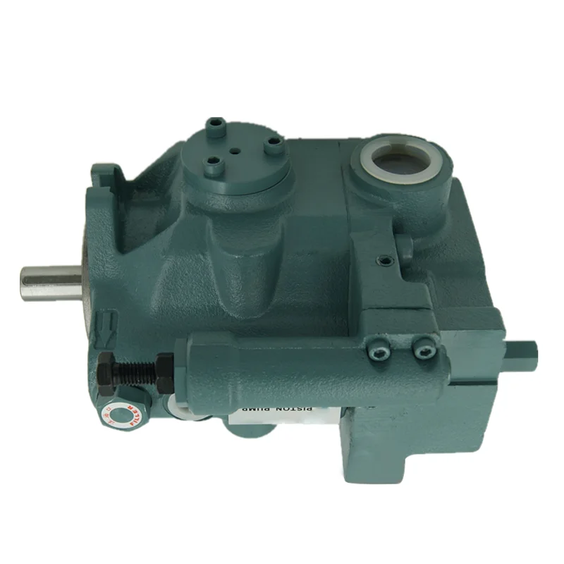
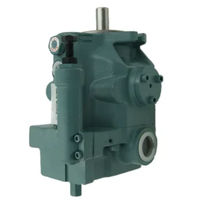
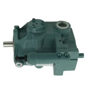
Product Overview
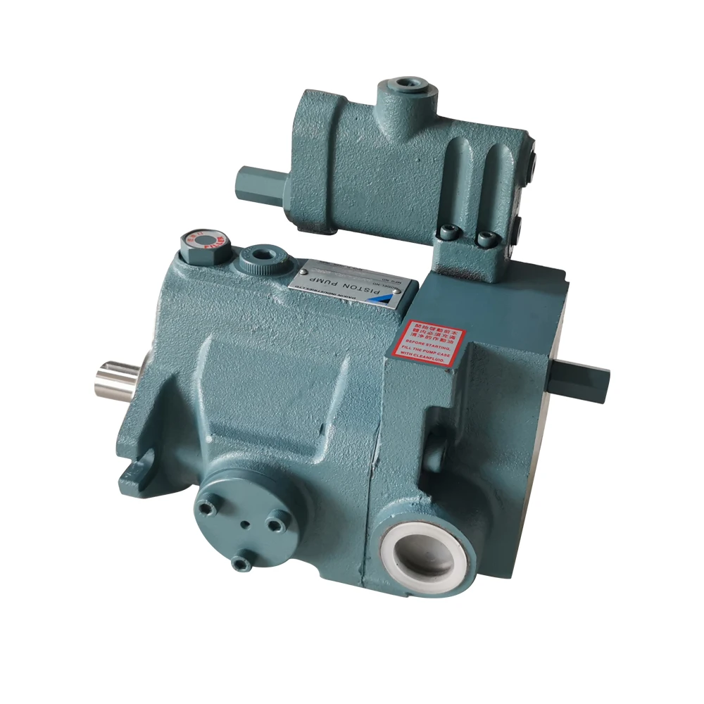
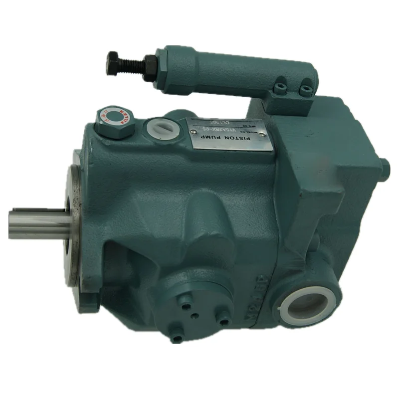
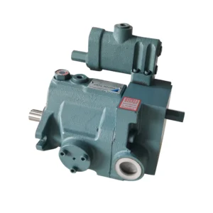
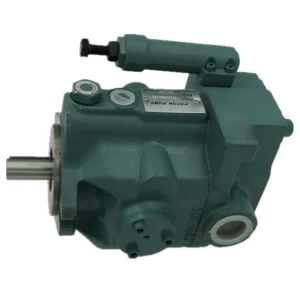
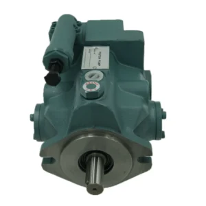
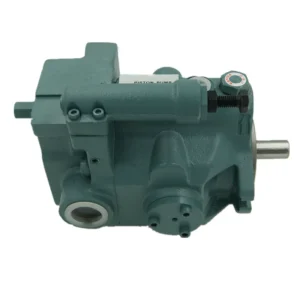
The V15A3RX-95, V15A2RX-95, and V15A1RX-95 are the 15-size core models within the Daikin V series of variable displacement axial piston pumps. The V series features a swashplate design where pump flow is proportional to drive speed and displacement, with swashplate inclination angle automatically and steplessly adjusted via a pressure compensator. The series is renowned for low noise, high efficiency, and high reliability, covering displacements from 8 to 70 cc/rev with a nominal pressure of 7 MPa and maximum working pressure of 21 MPa.
Model Code Breakdown (for procurement and engineering reference):
V: Daikin V series variable displacement piston pump
15: Nominal size, geometric displacement 14.8 cm³/rev
A: Pressure compensator control type
1 / 2 / 3: Pressure adjustment range codes. 1 = 0.8–7 MPa, 2 = 1.5–14 MPa, 3 = 3.5–21 MPa
RX: R = clockwise rotation (viewed from shaft end), X = side port connection
95: Design number, applicable to V15 and V38 sizes
Drop-in Replacement Advantage: Manufactured to exact Daikin OEM specifications, these pumps achieve complete drop-in interchangeability with the original V series for mounting flange, shaft dimensions, port layout, and pressure compensator control interface. Every pump undergoes 100% simulated load testing prior to shipment, validating pressure compensator response, volumetric efficiency, and thermal stability under conditions replicating real-world duty cycles.
Technical Specifications
Model V15A3RX-95:
Model Code: V15A3RX-95
Series: Daikin V Series (Variable Axial Piston Pump, Swashplate Design)
Nominal Size: 15
Geometric Displacement: 14.8 cm³/rev
Nominal Pressure: 7 MPa (70 bar)
Maximum Working Pressure: 21 MPa (210 bar)
Pressure Adjustment Range: 3.5–21 MPa (35–210 kgf/cm²)
Permissible Speed Range: 500–1800 r/min
Maximum Flow at 1800 rpm: Approx. 26.6 L/min
Control Type: Pressure Compensator Control (Type A), mechanically adjustable
Rotation: Clockwise (viewed from shaft end)
Port Connection: Side ports (X code)
Housing Material: Cast Iron
Seal Material: NBR, suitable for petroleum-based hydraulic fluid
Noise Level: Approx. 68 dB
Dimensions: 168.0 × 191 × 150 mm
Mass: Approx. 14.5 kg
Model V15A2RX-95:
Model Code: V15A2RX-95
Series: Daikin V Series (Variable Axial Piston Pump, Swashplate Design)
Nominal Size: 15
Geometric Displacement: 14.8 cm³/rev
Nominal Pressure: 7 MPa (70 bar)
Maximum Working Pressure: 14 MPa (140 bar)
Pressure Adjustment Range: 1.5–14 MPa (15–140 kgf/cm²)
Permissible Speed Range: 500–1800 r/min
Maximum Flow at 1800 rpm: Approx. 26.6 L/min
Control Type: Pressure Compensator Control (Type A), mechanically adjustable
Rotation: Clockwise (viewed from shaft end)
Port Connection: Side ports (X code)
Housing Material: Cast Iron
Seal Material: NBR, suitable for petroleum-based hydraulic fluid
Noise Level: Approx. 68 dB
Dimensions: 168.0 × 191 × 150 mm
Mass: Approx. 14.5 kg
Model V15A1RX-95:
Model Code: V15A1RX-95
Series: Daikin V Series (Variable Axial Piston Pump, Swashplate Design)
Nominal Size: 15
Geometric Displacement: 14.8 cm³/rev
Nominal Pressure: 7 MPa (70 bar)
Pressure Adjustment Range: 0.8–7 MPa (8–70 kgf/cm²)
Permissible Speed Range: 500–1800 r/min
Maximum Flow at 1800 rpm: Approx. 26.6 L/min
Control Type: Pressure Compensator Control (Type A), mechanically adjustable
Rotation: Clockwise (viewed from shaft end)
Port Connection: Side ports (X code)
Housing Material: Cast Iron
Seal Material: NBR, suitable for petroleum-based hydraulic fluid
Mass: Approx. 14.5 kg
V Series Displacement Size Reference:
V8: 8.0 cm³/rev
V15: 14.8 cm³/rev
V23: 23.0 cm³/rev
V38: 37.7 cm³/rev
V50: 51.6 cm³/rev
V70: 69.8 cm³/rev
Key Technical Advantages
1. Swashplate Design with Low Noise Operation
The V series employs a swashplate axial piston variable pump design. By optimizing swashplate structural rigidity combined with frame design based on the latest measurement and analysis technology, operating noise is dramatically reduced. The series maintains low noise performance across the entire pressure range, with a noise level of approximately 68 dB, particularly suitable for machine tools and industrial environments with strict noise control requirements.
2. Pressure Compensator Control with High Efficiency
The V15A3RX-95, V15A2RX-95, and V15A1RX-95 all employ pressure compensator control (Type A). When system pressure reaches the setpoint, the compensator automatically reduces pump displacement, maintaining only leakage compensation flow to minimize heat generation and power loss. Pressure is adjusted via the PC valve adjustment screw: clockwise rotation increases pressure, counterclockwise rotation decreases pressure. Three pressure adjustment ranges (0.8–7 MPa / 1.5–14 MPa / 3.5–21 MPa) cover diverse system requirements with flexible selection.
3. Compact Lightweight Design with High Power Density
The V series employs a supported swashplate design, achieving small lightweight construction and high voltage output, thereby improving output power per unit weight. The V15 size measures only 168.0 × 191 × 150 mm with a mass of approximately 14.5 kg. The compact structure makes it particularly suitable for space-constrained industrial hydraulic systems.
4. High Reliability with Long Service Life
The V series employs a ball valve plate design with appropriate oil pressure balance, expanding the operating condition range and achieving high efficiency output. The excellent wear-resistant ball valve plate enhances anti-pollution characteristics and extends service life. The series features high responsivity, high stability, and long life, effectively improving main machine reliability.
Application Areas
Machine Tools: CNC machine hydraulic systems, hydraulic fixtures, hydraulic chucks, precision grinders
Plastics Machinery: Injection molding machine clamp and injection hydraulic systems (V series is primarily used for machine tools, forging, and plastic forming machines)
Forging Equipment: Small hydraulic presses, bending machines, shearing machine hydraulic power sources
Industrial Automation: Hydraulic actuators, automated production line hydraulic systems
General Industrial Hydraulic Power Units: Small to medium hydraulic power units, central oil supply systems
Expert Maintenance Tips
1. Hydraulic Fluid Cleanliness
V series pumps are sensitive to fluid contamination. System fluid cleanliness must be maintained at NAS Grade 10 or better. The return line must have a line-type filter of 10 μm or under. Recommended fluids are clean petroleum-based hydraulic oils equivalent to ISO VG32 or VG46, with viscosity range 20–400 mm²/s and temperature 0–60°C both simultaneously satisfied. Replace filter elements at 500 hours after first commissioning, then every 1,000 operating hours or 6 months, whichever comes first.
2. Installation Alignment and Filling Port Orientation
When installing the pump, the filling port must be positioned upwards. Ensure drive shaft alignment, employing a flexible coupling whenever possible. Permissible suction pressure at the pump inlet port is between -16.7 and +50 kPa. The pump suction height must be within one meter from the oil level in the reservoir.
3. Case Drain Line Requirements
The case drain line must be installed independently, ensuring pressure within the pump housing is maintained at a normal pressure of less than 0.1 MPa and surge pressure of less than 0.5 MPa. The pipe end must be submerged in oil to prevent air ingestion. Never tie the drain line into the main system return line.
4. Pre-Start Priming and Air Bleeding
Before first start, fill the pump housing with clean hydraulic fluid. If the pump is mounted above the fluid level, fill through the outlet port; if mounted below the fluid level, loosen the outlet fitting to allow fluid to displace air. Position controls at neutral (zero displacement) and run at low speed for approximately 5 minutes, confirming air is fully expelled before applying load.
5. Pressure Compensator Setting
Set the pressure compensator 1.5–2 MPa above the maximum working load pressure, but never exceeding the pressure adjustment range upper limit of the selected model. Adjust only with the system at zero load. Rotate the adjustment screw slowly and verify stable pressure gauge readings before proceeding. Never adjust the compensator while the system is under pressure. Excessive loosening of the adjustment screw may cause oil leakage from the threaded portion; do not loosen the screw beyond the pressure adjustment range.